
Ametek 9933 Manuals
Manuals and User Guides for Ametek 9933. We have 3 Ametek 9933 manuals available for free PDF download: User Manual, Operator's Manual With Essential Health And Safety Requirements, Manual
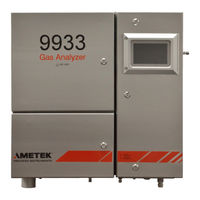
Ametek 9933 User Manual (301 pages)
Gas Analyzer
Brand: Ametek
|
Category: Measuring Instruments
|
Size: 25 MB
Table of Contents
Advertisement
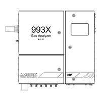
Ametek 9933 Operator's Manual With Essential Health And Safety Requirements (79 pages)
Gas Analyzer Class I, Division 2 and ATEX/IECEx Zone 2
Brand: Ametek
|
Category: Measuring Instruments
|
Size: 4 MB
Table of Contents
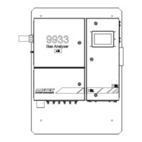
Ametek 9933 Manual (71 pages)
Gas Analyzer Class I, Division 2 and ATEX/IECEx Zone 2
Brand: Ametek
|
Category: Measuring Instruments
|
Size: 4 MB
Table of Contents
Advertisement