Sign In
Upload
Manuals
Brands
Allied Telesis Manuals
Switch
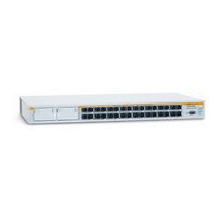
AT-8516F/SC Series
Allied Telesis AT-8516F/SC Series Manuals
Manuals and User Guides for Allied Telesis AT-8516F/SC Series. We have
7
Allied Telesis AT-8516F/SC Series manuals available for free PDF download: Installation Manual, Brochure, Datasheet
Allied Telesis AT-8516F/SC Series Installation Manual (90 pages)
AT-8500 Series Layer 2+ Fast Ethernet Switches
Brand:
Allied Telesis
| Category:
Switch
| Size: 2 MB
Table of Contents
Installation Guide
1
Electrical Safety and Emissions Standards
3
Translated Safety Statements
4
Table of Contents
5
Preface
11
Safety Symbols Used in this Document
12
Table 1. Safety Symbols
12
Where to Find Web-Based Guides
13
Contacting Allied Telesis
14
Online Support
14
Email and Telephone Support
14
Returning Products
14
For Sales or Corporate Information
14
Warranty
14
Management Software Updates
14
Chapter 1: Overview
15
Model Configurations
16
Table 2. Model Configurations
16
Model Descriptions
17
At-8516F/Sc
17
Figure 1. AT-8516F/SC Switch Front and Back Panels
17
At-8524M
18
Figure 2. AT-8524M Switch Front and Back Panels
18
At-8524Poe
19
Figure 3. AT-8524POE Switch Front and Back Panels
19
At-8550Gb
20
Figure 4. AT-8550GB Switch Front and Back Panels
20
At-8550Sp
21
Figure 5. AT-8550SP Switch Front and Back Panels
21
Port Descriptions
22
10/100Base-TX Twisted Pair Ports
22
10/100/1000Base-T Twisted Pair Ports
24
100Base-FX Fiber Optic Ports
25
Power over Ethernet
27
Power Budgeting
27
Implementation
28
Table 3. IEEE 802.3Af Class Vs. Power Levels
28
GBIC and SFP Slots
29
Figure 7. SFP Transceiver
29
Figure 6. GBIC Module
29
Module Expansion Slots
30
Leds
31
Twisted Pair Port Leds and the LED Mode Select Button
31
Table 4. Leds for the 10/100Base-TX Twisted Pair Ports on the AT-8524M, AT-8550GB, and AT-8550SP Switches
31
Fiber Optic Port Leds
34
Table 6. Leds for the 10/100Base-TX Twisted Pair Ports on the AT-8524POE Switch
34
GBIC and SFP Expansion Slot Leds
35
Table 7. Leds for the Fiber Optic Ports on the AT-8516F/SC Switch
35
System Leds
36
Table 9. System Leds
36
RS-232 Terminal Port
37
Power Options and Connectors
38
RPS Connector
38
Figure 8. AT-RPS3004 Redundant Power Supply Unit
38
AC Power Connector
39
DC Power Connector
39
A few Basics about Ethernet Switching
40
MAC Address Table
40
Duplex Mode
40
Store and Forward
41
Back Pressure and Flow Control
41
Figure 9. Power Workgroup Topology
43
Network Topologies
43
Power Workgroup Topology
43
Collapsed Backbone Topology
43
Mixed Topology
44
Figure 10. Collapsed Backbone Topology
44
Figure 11. Mixed Topology
45
Chapter 2: Installation
47
Reviewing Safety Precautions
48
Selecting a Site for the Switch
51
Planning the Installation
52
Table 10. Twisted Pair Cabling and Distances
52
Table 11. Fiber Optic Cabling and Distances
53
Unpacking the Switch
54
Installing the Switch in a Rack
55
Figure 12. Rack Mount Bracket Positions
55
Figure 13. Removing the Feet
56
Installing an Optional Expansion or Stacking Module
58
Figure 14. Removing the Expansion Slot Faceplate
58
Figure 16. Securing the Module in the Expansion Slot
59
Figure 15. Installing a Module
59
Installing an Optional GBIC
60
Figure 17. Optical Bore and Ferrule of GBIC Module
61
Figure 18. Installing a GBIC Module
61
Installing an Optional SFP Transceiver
62
Cabling the Switch
64
Cabling Twisted Pair Ports
64
Figure 19. Connecting the Twisted Pair Data Cables
64
Cabling Fiber Optic Ports
65
Figure 20. Removing the Dust Covers from the Fiber Optic Ports
65
Figure 21. Attaching a Fiber Optic Cable
66
Figure 22. Dual SC Port
66
Cabling Expansion Modules
67
Powering on an AC Powered Switch
68
Figure 23. Connecting the AC Power Cord
68
Figure 24. Connecting the RPS DC Cable
69
Wiring and Powering on an DC Powered Unit
70
Figure 25. Positive, Ground, and Negative Terminals
70
Figure 27. Connecting the Stripped Wire
71
Figure 26. Stripped Wire
71
Starting a Local Management Session
73
Warranty Registration
75
Chapter 3: Troubleshooting
77
PWR LED Is off
77
Twisted Pair Port Link LED Is off
77
Fiber Optic Port Link LED Is off
78
Poe Device Is Not Receiving Power
79
Fault LED Is on Continuously
79
Cannot Establish a Local Management Session
80
Appendix A: Technical Specifications
81
Physical Specifications
81
Environmental Specifications
81
Power Specifications
82
Safety and Electromagnetic Emissions Certifications
82
RJ-45 Twisted Pair Port Pinouts
83
Figure 29. RJ-45 Connector and Port Pin Layout
83
Table 13. 10/100Base-T Port MDI/MDI-X Pin Signals with Poe
83
Table 12. 10/100Base-TX Port MDI/MDI-X Pin Signals
83
Table 14. MDI and MDI-X Pin Signals (1000Base-T)
84
AT-8516F/SC Fiber Optic Port Specifications
85
RS-232 Terminal Port Pinouts
86
Table 15. RS-232 Terminal Port Pin Signals
86
RPS Connector Port Pinouts
87
Figure 30. RPS 16-Pin Molex Connector Pin Layout
87
Table 16. Pin Definitions of the 16-Pin RPS Connector
87
Figure 31. AT-8524POE RPS Connector Pin Layout
88
Pin Definition
89
Dual SC Type Connector
90
Figure 32. Dual SC Connector
90
Advertisement
Allied Telesis AT-8516F/SC Series Installation Manual (114 pages)
AT-8500 Series Layer 2+ Fast Ethernet Switches
Brand:
Allied Telesis
| Category:
Switch
| Size: 1 MB
Table of Contents
Electrical Safety and Emission Statement
3
Table of Contents
4
How this Guide Is Organized
7
Preface
7
Document Conventions
8
Where to Find Web-Based Guides
9
Contacting Allied Telesyn
10
Online Support
10
Email and Telephone Support
10
Returning Products
10
For Sales or Corporate Information
10
Management Software Updates
10
Chapter 1 Overview
11
Model Descriptions
12
At-8516F/Sc
12
At-8524M
13
At-8524Poe
14
At-8550Gb
15
At-8550Sp
16
Hardware Features
17
10/100Base-TX Twisted Pair Ports
18
Type of Connector
18
Speed
18
Duplex Mode
18
Maximum Distance
19
Type of Cabling
19
Auto-MDI/MDI-X
19
Port Pinouts
19
10/100/1000Base-T Twisted Pair Ports
20
Type of Connector
20
Speed
20
Duplex Mode
20
Maximum Distance
20
Type of Cable
20
Auto-MDI/MDI-X
21
Port Pinouts
21
100Base-FX Fiber Optic Ports
22
Type of Connector
22
Speed
22
Duplex Mode
22
Maximum Distance
22
Type of Cable
22
Power over Ethernet
23
AT-8524Poe's Implementation of Poe
24
Power Budgeting
24
GBIC and SFP Expansion Slots
26
Module Expansion Slots
27
Twisted Pair Port Leds and the LED Mode Select Button
28
Fiber Optic Port Leds
32
GBIC and SFP Expansion Slot Leds
33
System Leds
34
Terminal Port
35
RPS Connector
36
AC Power Connector
37
DC Power Connector
38
A few Basics about Ethernet Switching
39
MAC Address Table
39
Duplex Mode
40
Store and Forward
41
Backpressure and Flow Control
41
Network Topologies
42
Power Workgroup Topology
42
Collapsed Backbone Topology
43
Mixed Topology
44
Chapter 2 Installation
45
Reviewing Safety Precautions
46
Selecting a Site for the Switch
47
Planning the Installation
48
Unpacking the Switch
50
Installing the Switch in a Rack
51
Installing an Optional Expansion or Stacking Module
53
For the AT-8516F/SC, AT-8524M, and AT-8524POE
53
Installing an Optional GBIC Module
56
For the AT-8550GB
56
Installing an Optional SFP Module
58
For the AT-8550SP
58
Cabling and Powering on the Switch
60
Wiring a DC Powered Unit
66
Starting a Local Management Session
69
Warranty Registration
71
Chapter 3 Troubleshooting
72
Appendix A Technical Specifications
77
Physical Specifications
77
Environmental Specifications
78
Power Specifications
79
Safety and Electromagnetic Emissions Certifications
80
Standards
81
SNMP Support
82
RJ-45 Twisted Pair Port Pinouts
83
AT-8516F/SC Fiber Optic Port Specifications
86
RS-232 Terminal Port Pinouts
87
RPS Connector Port Pinouts
88
Dual SC Type Connector
91
Appendix B
92
Translated Electrical Safety and Emission Information
92
Allied Telesis AT-8516F/SC Series Brochure (12 pages)
10 Gigabit Ethernet Switches and Fast Ethernet Switches
Brand:
Allied Telesis
| Category:
Switch
| Size: 0 MB
Advertisement
Allied Telesis AT-8516F/SC Series Datasheet (3 pages)
8500 SERIES Managed Fast Ethernet Switches with Enhanced Security and Layer 2-4 Intelligence
Brand:
Allied Telesis
| Category:
Switch
| Size: 0 MB
Table of Contents
Physical Characteristics
2
Fault Protection
2
Power over Ethernet
2
Power Characteristics
2
Management and Monitoring
2
Environmental Specifications
2
Ordering Information
3
Allied Telesis AT-8516F/SC Series Datasheet (3 pages)
Network Device Management Software
Brand:
Allied Telesis
| Category:
Software
| Size: 0 MB
Table of Contents
Media Converters
2
Ordering Information
3
Management Modules
3
Gigabit Interface Converters
3
Allied Telesis AT-8516F/SC Series Datasheet (1 page)
Redundant Power Supply Chassis and Power Module
Brand:
Allied Telesis
| Category:
Power Supply
| Size: 0 MB
Allied Telesis AT-8516F/SC Series Datasheet (2 pages)
Network Device Management Software
Brand:
Allied Telesis
| Category:
Software
| Size: 0 MB
Advertisement
Related Products
Allied Telesis AT-8550/SP Series
Allied Telesis AT-8524POE Series
Allied Telesis AT-8500 Series
Allied Telesis SwitchBlade AT-8550/GB
Allied Telesis AT-8518
Allied Telesis AT-8525
Allied Telesis AT-8550
Allied Telesis AT-8000GS/48
Allied Telesis AT-8848
Allied Telesis AT-8012M
Allied Telesis Categories
Switch
Network Router
Media Converter
Network Hardware
Wireless Access Point
More Allied Telesis Manuals
Login
Sign In
OR
Sign in with Facebook
Sign in with Google
Upload manual
Upload from disk
Upload from URL