Sign In
Upload
Manuals
Brands
Allen-Bradley Manuals
Controller
PowerFlex 527
Allen-Bradley PowerFlex 527 Manuals
Manuals and User Guides for Allen-Bradley PowerFlex 527. We have
5
Allen-Bradley PowerFlex 527 manuals available for free PDF download: Reference Manual, User Manual, Original Instructions Manual, Application Technique
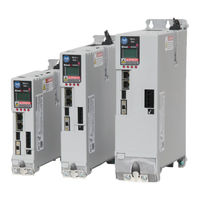
Allen-Bradley PowerFlex 527 Reference Manual (497 pages)
Integrated Motion on the EtherNet/IP Network
Brand:
Allen-Bradley
| Category:
Industrial Electrical
| Size: 12.35 MB
Table of Contents
Table of Contents
5
Additional Resources
11
Preface
11
Legal Notices
12
Integrated Motion on the Ethernet/Ip Network
15
Integrated Motion Axis Control Modes and Methods
16
Control Modes
16
Position Control Mode
17
Velocity Control Mode
18
Torque Control Mode
20
No Control Mode
21
Control Methods
21
Motion Instruction Compatibility
22
Chapter 1
15
Chapter 2 Acceleration Control Behavior
25
Acceleration Limiter
26
Load Observer
27
Command Generation Behavior
28
Command Data Sources
29
Command Fine Interpolation
30
Command Ramp Generator
33
Feedforward Signal Selection
34
Command Notch Filter
35
Current Control Behavior
35
Current Vector Limiter
36
Voltage Output
37
Current Feedback
37
Motor Commutation
38
Event Capture Behavior
38
Event Input Sources
39
Event Latches
40
Event Time Stamps
40
Fault and Alarm Behavior
41
Exceptions
41
Exceptions on
41
Rockwell Automation Publication MOTION-RM003I-EN-P - February
42
Absolute Position Recovery
43
Absolute Position Loss Without APR Faults
44
APR Fault Conditions
44
APR Fault Generation
45
APR Fault Examples
47
APR Recovery Scenarios
48
Reset an APR Fault
50
Motion Control Axis Behavior Model
51
Active Control Axis Behavior Model
52
Feedback Only Axis Behavior Model
54
CIP Motion Converter Axis Behavior Model
56
Motor Attributes Model
57
Position Control Behavior
58
Position Feedback Selection
59
Position PI Gains
60
Velocity Feedforward
60
Position Loop Output Filters
61
State Behavior
61
Torque Control Behavior
71
Torque Input Sources
72
Inertia Compensation
73
Friction Compensation
75
Torque Filters
77
Torque Limiter
78
Torque to Current Scaling
78
Velocity Control Behavior
79
Closed Loop Velocity Control
80
Open Loop Frequency Control
83
Chapter 3
87
Interpret the Attribute Tables
87
Chapter 3
89
Attribute Units
90
Device Function Codes
91
Tables CIP Data Types
91
Required Vs. Optional Axis Attributes
93
Identify Motion Axis Attributes Based on Device Function Codes
95
Attribute Conversion from SERCOS to Integrated Motion on the Ethernet/Ip Network
111
Drive Supported Optional Attributes
114
Kinetix 350 Drive Module Optional Attributes
116
Kinetix 5500 Hardwired STO Drive Module Optional Attributes
122
Kinetix 5500 Integrated STO Drive Module Optional Attributes
130
Kinetix 5700 Safety Drive Module Optional Attributes
138
Kinetix 5700 Advanced Safety Drive Module Optional Attributes
147
Kinetix 6500 Drive Module Optional Attributes
155
Powerflex 527 Axis Instance Optional Attributes
161
Powerflex 755 Standard Drive Module Optional Attributes
168
Powerflex 755 Safety Drive Module Optional Attributes
174
MSG Instruction Access Only Attributes
181
Rockwell Automation Publication MOTION-RM003I-EN-P - February
182
Acceleration Control Attributes on
185
APR Fault Attributes on
186
Chapter 4 Control Mode Attributes ....................................................................................................
187
Acceleration Control Attributes
187
DC Bus Control Attributes on
187
Acceleration Control Configuration Attributes
189
Command Reference Generation Attributes
191
Command Generator Configuration Attributes
191
Command Generator Signal Attributes
195
Current Control Configuration Attributes
196
Current Control Signal Attributes
201
Frequency Control Configuration Attributes
204
Frequency Control Signal Attribute
206
Position Loop Signal Attributes
206
Position Loop Configuration Attributes
208
Torque/Force Control Configuration Attributes
211
Torque/Force Control Signal Attributes
220
Velocity Loop Configuration Attributes
221
Velocity Loop Signal Attributes
228
CIP Axis Attributes
187
Data Attributes
233
Axis Info Attributes
234
Axis Statistical Attributes
235
CIP Axis Status Attributes
236
Event Capture Attributes
247
Drive Attributes
249
Drive General Purpose I/O Attributes
249
Drive Output Attributes
251
Power and Thermal Management Configuration Attributes
252
Power and Thermal Management Status Attributes
254
Drive Commissioning and Tuning Attributes
257
Auto-Tune Configuration Attributes
258
Hookup Test Configuration Attributes
266
Hookup Test Result Attributes
267
Inertia Test Configuration Attributes
269
Inertia Test Result Attributes
272
Motor Test Result Attributes
275
Faults and Alarms Attributes
279
APR Fault Attributes
279
Axis Exception Action Configuration Attributes
281
Axis Exception Action
283
Configuration Fault Attributes
287
CIP Error Codes
287
Exception Factory Limit Info Attributes
290
Exception User Limit Configuration Attributes
292
Exception, Fault and Alarm Attributes
293
Initialization Faults Attributes
295
Standard Initialization Faults
296
Rockwell Automation Specific Initialization Faults
296
Module/Node Fault and Alarm Attributes
297
Feedback Attributes
302
Feedback Interface Types
302
Feedback Configuration Attributes
304
General Feedback Info Attributes
316
General Feedback Signal Attributes
316
Motion Control Attributes
317
Motion Control Configuration Attributes
317
Motion Control Interface Attributes
323
Motion Control Signal Attributes
330
Motion Control Status Attributes
341
Motion Database Storage Attributes
352
Motion Dynamic Configuration Attributes
354
Motion Homing Configuration Attributes
357
Motion Planner Configuration Attributes
367
Motion Planner Output Attributes
374
Motion Scaling Attributes
375
Motion Resolution Value Examples
386
Motor Attributes
388
General Linear Motor Attributes
388
General Motor Attributes
389
General Permanent Magnet Motor Attributes
396
General Rotary Motor Attributes
399
Induction Motor Attributes
401
Linear PM Motor Attributes
404
Interior Permanent Magnet Motor Attributes
406
Load Transmission and Actuator Attributes
409
Rotary PM Motor Attributes
412
Safety Attributes
414
Axis Safety Status Attributes
414
Guard Safety Attributes
425
Guard Safety Status Attributes
426
Stopping and Braking Attributes
431
Stopping Sequences
445
Proving Operational Sequences
448
DC Bus Control Attributes
451
Start Inhibits Attributes
453
Standard Start Inhibits
454
Rockwell Automation Specific Start Inhibits
455
Exceptions
456
Standard Exceptions
456
Standard CIP Axis Fault and Alarm Names
461
Rockwell Automation Specific Exceptions
465
Rockwell Automation Specific CIP Axis Fault Names
467
Rockwell Automation Specific CIP Axis Alarm Names
468
Rockwell Automation Publication MOTION-RM003I-EN-P - February
469
Module Configuration Attributes
472
Chapter 5 Module Configuration Block Attributes ........................................................................ 471
473
Module Class Attributes
473
Module Axis Attributes
474
Module Feedback Port Attributes
489
Module Timing Attributes
490
Module Support Attributes
492
Index
495
Advertisement
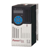
Allen-Bradley PowerFlex 527 User Manual (354 pages)
Integrated Motion on the EtherNet/IP Network, Configuration and Startup
Brand:
Allen-Bradley
| Category:
Controller
| Size: 13.01 MB
Table of Contents
Table of Contents
3
Additional Resources
9
Preface
9
Summary of Changes
9
Chapter 1
11
Controller, Communication, Drive, and Software Options
11
Module Options
11
Integrated Motion on Ethernet/Ip Drives
13
Software Options
13
Options for Powerflex 755 Drives
16
Configuration and Startup Scenarios
18
Help for Selecting Drives and Motors
20
Create a Controller Project
21
Configure Integrated Motion Control Using Kinetix Drives
21
Chapter 2
24
Set Time Synchronization
24
Add an Ethernet Communication Module
26
Network
27
Network
28
Network
29
Network
31
Add a Kinetix Ethernet/Ip Drive
32
Chapter 3
36
Configure the Safety Category - Kinetix 5500 Drives
36
Configure the Power Options
37
Configure Digital Inputs
39
Create an Associated Axis
40
Create an Axis for a Kinetix Drive
40
Establish Feedback Port Assignments
41
Create a Motion Group
42
Set the Base Update Period
44
Configure the Axis Properties
46
Configure the Associated Axis and Control Mode
47
Specify the Motor Data Source
50
Choose the Catalog Number as the Motor Data Source
51
Choose Nameplate as the Motor Data Source
52
Choose Motor NV as the Motor Data Source
53
Assign Motor Feedback
54
Display Motor Model Information
54
Configure the Load Feedback
55
Configure Feedback Only Axis Properties
57
Configure Integrated Motion Control Using Kinetix 5700 Drives
59
Configure the Master Feedback
57
Chapter 4 Ethernet/Ip Drive
60
Configure the DC-Bus Power Supply and Associate an Axis
60
Configure the Regenerative Bus Supply
64
Continue Inverter Configuration
69
Configure the Inverter Drives
72
Create an Associated Axis and Establish Feedback Assignments for an Inverter Drive
80
Create a Motion Group
83
Set the Base Update Period
84
Configure the Axis Properties
86
Configure the Associated Axis and Control Mode
88
Specify the Motor Data Source
91
Choose the Catalog Number as the Motor Data Source
91
Choose Nameplate as the Motor Data Source
93
Choose Motor NV as the Motor Data Source
94
Assign Motor Feedback
95
Display Motor Model Information
95
Configure the Load Feedback
97
Configure the Master Feedback
98
Add a Powerflex 755 Drive
99
Configure Integrated Motion Using a Powerflex 755 Drive
99
Chapter 5
101
Select a Peripheral Feedback Device and Slot Assignment
101
Select an I/O Device
102
Assign a Power Structure
104
Configure Power Options
106
Configure Digital Inputs
107
Configure Digital Outputs
108
Create an Associated Axis
109
Create an Axis for a Powerflex 755 Drive
109
Establish Feedback Port Assignments
110
Create a Motion Group
111
Set the Base Update Period
112
Configure the Axis Properties
115
Configure the Associated Axis and Control Mode
116
Specify the Motor Data Source
119
Choose Catalog Number as the Motor Data Source
119
Choose Nameplate as the Motor Data Source
121
Choose Drive NV as the Motor Data Source
122
Display Motor Model Information
123
Assign Motor Feedback
125
Rockwell Automation Publication MOTION-UM003K-EN-P - January
126
Configure Integrated Motion Using a Powerflex 527 Drive
129
Add a Powerflex 527 Drive
130
Chapter 6
130
Set the Network Configuration
130
Configure the Powerflex 527 Drive
132
Configure the Drive with Hard-Wired Safety Connections
132
Configure the Drive with Integrated Safety Connections
134
Configure Power Options
137
Configure Digital Inputs
138
Create an Axis for a Powerflex 527 Drive
138
Create the Motion Group
139
Configure the Axis Properties
140
Configure the Associated Axis and Control Mode
142
Chapter 7 About Axis Scheduling
146
Timing Model
147
One Cycle Timing
148
Two Cycle Timing
149
Axis Scheduling Configuration
150
Configure the Update Periods
151
Motion Utilization
158
Example 1: Position Loop with Motor Feedback Only
159
Chapter 8
163
Example 2: Position Loop with Dual Feedback
163
Example 3: Feedback Only
167
Example 4: Kinetix 5500 Drive, Velocity Loop with Motor Feedback
172
With Motor Feedback
176
Example 5: Kinetix 350 Drive, Position Loop with Motor Feedback
176
With no Feedback
180
Example 6: Kinetix 5700 Drive, Frequency Control with no Feedback
180
Example 7: 842E-CM Integrated Motion Encoder with Master Feedback
183
Chapter 9
188
UFB Feedback Device
188
Example 1: Position Loop with Motor Feedback Via a UFB Feedback Device
188
Example 2: Position Loop with Dual Motor Feedback Via a UFB Feedback Device
191
Example 3: Velocity Loop with Motor Feedback Via a UFB Feedback Device
196
UFB Feedback Device
196
Example 4: Velocity Loop with no Feedback
199
Example 5: Frequency Control with no Feedback
202
Example 6: Torque Loop with Feedback
206
This Chapter Provides Example Axis Configurations When Using a
209
Example 1: Frequency Control with no Feedback
210
Chapter 10 Example 2: Velocity Control with Motor Feedback
214
The Powerflex 527 Drive Example 2: Velocity Control with Motor Feedback
214
Example 3: Position Control with Motor Feedback
217
Chapter 11 Commission an Axis Scaling
222
Direct Coupled Rotary
223
Direct Coupled Linear
224
Rotary Transmission
224
Linear Actuator
225
Changing Scaling Factors
225
Scaling
222
Hookup Tests
226
Run a Motor and Feedback Test
228
Run a Motor Feedback Test
230
Run a Marker Test
230
Applying the Commutation Hookup Test
232
Unknown Commutation Offset
232
Verification of Known Commutation Offset
233
Non-Standard or Incorrect Wiring
233
Run a Commutation Test
234
Autotune
235
Polarity
235
Load
239
Load Observer
241
Benefits of Load Observer
241
How Load Observer Functions
241
Load Observer Configuration
242
Adaptive Tuning
243
Benefits of Adaptive Tuning
244
How Adaptive Tuning Functions
244
Adaptive Tuning Configuration
245
Status Bits
248
Load Ratio Data from Motion Analyzer
249
Test an Axis with Motion Direct Commands
249
Access Motion Direct Commands for an Axis or Group
250
Motion Direct Commands
252
Rockwell Automation Publication MOTION-UM003K-EN-P - January
253
Chapter 12 Guidelines for Homing
256
Active Homing
256
Passive Homing
257
Homing
256
Examples
258
Active Homing
258
Passive Homing
261
Absolute Position Recovery (APR)
262
APR Terminology
262
Controllers
262
Absolute Feedback Device
263
SERCOS Versus Integrated Motion on Ethernet Networks
263
APR Scenarios
264
APR Faults
269
APR Fault Conditions
269
APR Fault Generation
270
Scaling
272
Online Scaling
272
Resetting an APR Fault
273
Absolute Position Loss Without APR Faults
273
Behavior of APR for Incremental Encoders
274
Saving an ACD File Versus Upload of a Project
274
Chapter 13 When to Manually Tune an Axis
275
Axis Configuration Types
275
Current Tuning Configuration
276
Loop Responses
277
Motion Generator and Motion Direct Commands
279
Manual Tune
275
Additional Tune
281
Feedforward Parameters
281
Compensation Parameters
282
Filters Parameters
283
Limits Parameters
284
Planner Parameters
284
Configure Torque Values
285
Monitor Tags with the Quick Watch Window
285
Use Motion Generator
286
Faults and Alarms Dialog Box
289
Chapter 14
291
Quickview Pane
291
Connection Faults and Errors
292
Data Monitor
292
Drive Status Indicators
292
Manage Motion Faults
293
Troubleshoot Faults
293
Configure the Exception Actions for AXIS_CIP_DRIVE
294
Inhibit an Axis
297
Example: Inhibit an Axis
298
Example: Uninhibit an Axis
299
Digital I/O Status Indicators
300
Parameter Dialog-Box Listings
303
Appendix A
305
Appendix B
305
Definition of Jerk
305
Choose a Profile
306
Use % of Time for the Easiest Programming of Jerk
307
Velocity Profile Effects
308
Jerk Rate Calculation
308
Profile Operand
313
Program a Velocity Profile and Jerk Rate
305
Enter Basic Logic
316
Example Motion Control Program
317
Download a Project
318
Choose a Motion Instruction
318
Troubleshoot Axis Motion
321
Why Does My Axis Accelerate When I Stop It
321
Why Does My Axis Overshoot Its Target Speed
322
Why Is There a Delay When I Stop and then Restart a Jog
325
Why Does the Axis Reverse Direction
327
When Stopped and Started
327
Programming with the MDSC Function
329
Powerflex Out-Of-Box Configuration
332
Recommended Out-Of-Box Settings
332
Setting the ACO/AVO Attributefor PF527 Drives Only
336
Glossary
337
Index
341
Rockwell Automation Publication MOTION-UM003K-EN-P - January
342
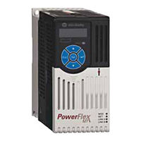
allen bradley PowerFlex 527 User Manual (177 pages)
Adjustable Frequency AC Drive
Brand:
allen bradley
| Category:
Controller
| Size: 22.94 MB
Table of Contents
Important User Information
2
New and Updated Information
3
Table of Contents
5
Additional Resources
9
Overview
9
Preface
9
Who Should Use this Manual
9
Drive Frame Sizes
10
Manual Conventions
10
Product Environmental Information
10
General Precautions
11
Catalog Number Explanation
12
Chapter 1
13
Installation/Wiring
13
Mounting Considerations
13
Minimum Mounting Clearances
14
Ambient Operating Temperatures
15
Current Derating Curves
15
Storage
16
AC Supply Source Considerations
17
Ungrounded Distribution Systems
17
General Grounding Requirements
18
Input Power Conditioning
18
Ground Fault Monitoring
19
Motor Ground
19
RFI Filter Grounding
19
Shield Termination - SHLD
19
Fuses and Circuit Breakers
20
Fusing
20
Fuses and Circuit Breakers for Powerflex 527
21
Power and Control Module
25
Separating the Power and Control Module
25
Connecting the Power and Control Module
26
Control Module Cover
28
Power Module Terminal Guard
28
Motor Cable Types Acceptable for 100...600 Volt Installations
29
Power Wiring
29
Shielded/Armored Cable
30
Unshielded
30
Output Disconnect
31
Recommended Shielded Wire
31
Reflected Wave Protection
31
I/O Wiring
32
Motor Start/Stop Precautions
32
Power Terminal Block
32
Maximum Control Wire Recommendations
33
Signal and Control Wire Types
33
Control I/O Terminal Block
34
Powerflex 527 Control I/O Wiring Block Diagram
34
Control I/O Terminal Designations
35
CE Conformity
36
Tag Attributes in Logix Designer for Inputs and Outputs
36
EMC Directive (2004/108/EC)
37
General Considerations
37
Low Voltage Directive (2006/95/EC)
37
Machinery Directive (2006/42/EC)
37
Installation Requirements
38
Connections and Grounding
40
Emission Compliance and Installation Requirements Table
40
Maximum Motor Cable Length
40
Additional Installation Requirements
41
Recommended Placement of EMC Cores Relative to External Filter
42
Recommended Placement of EMC Cores with Optional EMC Plate
42
Chapter 2
43
Drive Startup Task List
43
Prepare for Drive Start-Up
43
Start up
43
Start, Stop, Direction, and Speed Control
44
Understanding the Powerflex 527 Display and Indicators
44
LCD Display and Status Indicators
45
Device and Axis States
46
Startup Sequence
46
Information Display
47
Network Configuration
47
Configuring Network Settings
48
Settings Options
48
Real-Time Information Display
49
Drive Programming Tools
50
Language Support
50
Using the Ethernet Port
50
Configure the Drive
51
Configuring the Powerflex 527 Drive with Integrated Motion
51
Set the Network Configuration
51
Chapter 3
52
Configure the Logix Designer Application Project
52
Configure the Logix5000 Controller
52
Add a Powerflex 527 Drive
57
Configure Drive with Hardwired Safety Connections
59
Configure the Powerflex 527 Drive
59
Configure Drive with Integrated Safety Connections
61
Continue Drive Configuration
64
Configure the Motion Group
67
Configure Axis Properties
68
Configure Induction Motors Axis Properties (Velocity Loop)
73
Configure Induction Motors Axis Properties (Position Loop)
77
Download the Program
81
Apply Power to the Powerflex 527 Drive
82
Test and Tune the Axes - Velocity and Position Control Modes
83
Tune the Axes
85
Certification
87
Important Safety Considerations
87
Powerflex 527 Integrated Safe Torque-Off
87
Category 3 Requirements According to ISO 13849
88
Chapter 4
88
Description of Operation
88
Performance Level (PL) and Safety Integrity Level (SIL)
88
Stop Category Definition
88
Probability of Dangerous Failure Per Hour (PFH)
89
Safe Torque-Off (STO) Feature
89
As-Shipped Safety Configuration
90
Safe Torque-Off Feature Bypass
90
Out-Of-Box (OOB) Safety State
91
Recognizing the Out-Of-Box State
91
Restoring the Drive to the Out-Of-Box State
91
Safe Torque-Off Status
93
Explicit Messages
94
Safety Supervisor State
94
Propose TUNID Blocked
95
Safe Torque-Off Faults
95
Safe Torque-Off Mode
95
Description of Operation
97
Hardwired Control of Safe Torque-Off
97
Operation of Hardwired Safe Torque-Off
97
Selection of Hardwired Safe Torque-Off
97
System Operation When Inputs Are Meeting Timing Requirements
98
Troubleshoot the Safe Torque-Off Function
98
Chapter 5
100
Safe Torque-Off Connector Data
100
Safe Torque-Off Wiring Requirements
100
Wire the Safe Torque-Off Circuit
100
Safe Torque-Off Specifications
101
Compatible Safety Controllers
103
Network Control of Safe Torque-Off
103
Selection of Network Safe Torque-Off
103
Network Safe Torque-Off Specifications
104
Safe Torque-Off Assembly Tags
104
Safety Application Requirements
104
STO Fault Reset
105
Reset Safe Torque-Off Fault Diagram
106
Troubleshoot Network Safe Torque-Off
106
Chapter 6
107
Replacing an Integrated Safety Drive in a Guardlogix System
107
Understanding Integrated Safety Drive Replacement
107
Replace with “Configure Only When no Safety Sign. Exists” Enabled
108
Replacing a Powerflex 527 Drive
108
Setting the SNN with a Guardlogix Controller
108
Replacement with “Configure Always” Enabled
113
Motion Direct Commands in Motion Control Systems
114
Logix Designer Application Warning Messages
115
Understanding STO Bypass When Using Motion Direct Commands
115
Torque Permitted in a Multi-Workstation Environment
118
Warning Icon and Text in Axis Properties
118
Functional Safety Considerations
120
Chapter 7
121
Display Interface
121
Interpret Status Indicators
121
Safety Precautions
121
Troubleshooting
121
Fault Codes
122
FLT Sxx Fault Codes
122
FLT MXX Fault Codes
124
INHIBIT Fault Codes
125
INIT FLT Fault Codes
125
NODE FLT Fault Codes
125
NODE ALARM Fault Codes
126
Powerflex 527 Drive Status Indicators
126
Fault Status Indicator
127
Module Status Indicator
127
Network Status Indicator
127
General Troubleshooting
128
Link a Status Indicator (Ethernet Port 1)
128
Link a Status Indicator (Ethernet Port 2)
128
Logix5000 Controller and Drive Behavior
129
Powerflex 527 Drive Exception Action Definitions
130
Powerflex 527 Drive Exception Behavior
130
Drive Behavior, FLT Sxx Fault Codes
131
Logix Designer Axis Properties - Actions Category
131
Drive Behavior, FLT MXX Fault Codes
132
Drive Behavior, NODE FLT XX Fault Codes
132
Certifications
133
Supplemental Drive Information
133
Appendix A
134
Environmental Specifications
134
Control Data
135
Electrical Data
135
Protection Data
135
Technical Specifications
135
Control Inputs Data
137
Control Outputs Data
137
Encoder Data
137
Estimated Watts Loss (Rated Load, Speed & PWM)
138
Power Specifications
138
Input Current Scaled by Motor Current
139
Accessories and Dimensions
141
Catalog Number Description
141
Powerflex 527 Drive Ratings
141
Product Selection
141
Dynamic Brake Resistors
142
EMC Line Filters
143
EMC Plates
144
Bulletin 160 to Powerflex 527 Mounting Adapter Plate
145
Control Module Fan Kit / Incremental Encoder Input Option
145
IP 30/NEMA 1/UL Type 1 Kit
145
Powerflex 527 Power Module Replacement Parts
145
Bulletin 1321-3R Series Line Reactors
147
Control Module Replacement Parts
147
Other Parts
147
Accessories and Dimensionsappendix Bproduct Dimensions
149
Drive Weight
149
IP 20/Open Type – Frame a Dimensions
149
IP 20/Open Type – Frame B Dimensions
150
IP 20/Open Type – Frame C Dimensions
150
IP 20/Open Type – Frame D Dimensions
151
IP 20/Open Type – Frame E Dimensions
151
Control Module Fan Kit Specifications
152
IP 20/Open Type with Control Module Fan Kit – Frame A...C Dimensions
152
IP 20/Open Type with Control Module Fan Kit – Frame D...E Dimensions
153
IP 30/NEMA 1/UL Type 1 – Frame a Dimensions
154
IP 30/NEMA 1/UL Type 1 – Frame B Dimensions
155
IP 30/NEMA 1/UL Type 1 – Frame C Dimensions
156
IP 30/NEMA 1/UL Type 1 – Frame D Dimensions
157
IP 30/NEMA 1/UL Type 1 – Frame E Dimensions
158
EMC Line Filter – Frame a Dimensions
159
EMC Line Filter – Frame B Dimensions
159
EMC Line Filter – Frame C Dimensions
160
EMC Line Filter – Frame D Dimensions
160
EMC Line Filter – Frame E Dimensions
161
Replacing the Powerflex 527 Control Module Internal Fan
161
Out-Of-Box Configuration
163
Recommended Out-Of-Box Settings
163
Appendix C Setting the ACO/AVO Attribute
166
Appendix D
167
Encoder Option Card Usage
167
Installing the Encoder Option Card
167
Removing the Encoder Option Card
168
Encoder Interface
169
Encoder Wiring Examples
170
Wiring Notes
170
Index
171
Advertisement
Allen-Bradley PowerFlex 527 Original Instructions Manual (43 pages)
Technical Data, AC Drive Specifications
Brand:
Allen-Bradley
| Category:
Controller
| Size: 3.25 MB
Table of Contents
Table of Contents
1
Packaging and Mounting
2
Product Overview
2
Powerflex 527 AC Drives Feature
2
Design
2
Powerflex 527 AC Drive Advanced Features
3
Control Performance
3
I/O Wiring
3
Communications
3
Encoder Option Card
4
Feedback Details
4
Improved Ride through
4
Common DC Bus Installations
4
Communications and Software
5
Versatile Programming and Network Solutions
5
PC Programming Software
5
Safety Inside Using Safe Torque-Off Function
5
Powerflex 527 Drive Family
6
Catalog Number Explanation
7
Technical Specifications
8
Environmental Specifications
11
Certifications
12
Dimensions and Weights
13
Drive Dimensions and Weight
15
Mounting Considerations
15
Design Considerations
15
Minimum Mounting Clearances
16
Ambient Operating Temperatures
16
Current Derating Curves
17
Derating Guidelines for High Altitude
17
Disconnecting Movs
18
AC Supply Source Considerations
18
Storage
18
Debris Protection
18
Jumper Location (Typical)
19
Phase to Ground MOV Removal
19
Input Power Conditioning
19
General Grounding Requirements
20
Ground Fault Monitoring
20
Motor Ground
20
Shield Termination - SHLD
20
Motor Cable Types Acceptable for 100...600 Volt Installations
21
Unshielded
21
RFI Filter Grounding
21
Power Wiring
21
Shielded/Armored Cable
22
Recommended Shielded Wire
22
Reflected Wave Protection
22
Common Bus/Precharge Notes
23
Output Disconnect
23
Motor Start/Stop Precautions
23
Important Points to Remember about I/O Wiring
23
Recommended Control Wire for Digital I/O
24
Maximum Control Wire Recommendation
24
Signal and Control Wire Types
24
Machinery Directive (2006/42/EC)
24
Connections and Grounding
25
Powerflex 527 RF Emission Compliance and Installation Requirements
25
Bulletin 140M (Self-Protected Combination Controller)/Ul489 Circuit Breakers
26
Fusing
26
Circuit Breakers
26
Fuses and Circuit Breaker Ratings
26
Fuses and Circuit Breakers for Powerflex 527
27
100...120V 1-Phase Input Protection Devices – Frames A...B
27
200...240V 1-Phase Input Protection Devices – Frames A...B
27
200...240V 3-Phase Input Protection Devices – Frames A...E
28
380...480V 3-Phase Input Protection Devices – Frames A...E
29
525...600V 3-Phase Input Protection Devices – Frames A...E
30
Dynamic Brake Resistors
31
Accessories and Dimensions
31
EMC Line Filters
32
EMC Plates
33
Replacement Parts
33
Powerflex 527 Power Module
33
Powerflex 527 Control Module
35
Other Parts
35
Bulletin 1321-3R Series Line Reactors
35
380...480V 50/60 Hz 3-Phase
36
525...600V 50/60 Hz 3-Phase
36
Accessory Dimensions
37
Control Module Fan Kit – Dimensions Are in MM and (In.)
38
EMC Line Filter – Dimensions Are in MM and (In.)
39
EC Type Examination Certification
40
Safety Concept
40
Safe Torque-Off Function
40
Probability of Dangerous Failure Per Hour (PFH) Data
41
Safety Reaction Time
41
Additional Resources
41
Allen-Bradley PowerFlex 527 Application Technique (24 pages)
Safety Function: Actuator Subsystems - Stop Category 1, Drives with Safe Torque-off
Brand:
Allen-Bradley
| Category:
DC Drives
| Size: 0.91 MB
Table of Contents
Table of Contents
1
Important User Information
2
General Safety Information
3
Introduction
3
Safety Function Realization: Risk Assessment
3
Stop Safety Functions
4
Safety Function Requirements
4
Functional Safety Description
5
Bill of Material
6
Setup and Wiring
6
Configuration
11
Calculation of the Performance Level
13
Verification and Validation Plan
17
Additional Resources
22
Advertisement
Related Products
Allen-Bradley PowerFlex 525
Allen-Bradley PowerFlex 523
Allen-Bradley 5069 CompactLogix
Allen-Bradley 5069 Compact GuardLogix
Allen-Bradley GuardLogix 5570
Allen-Bradley SoftLogix 5800
Allen-Bradley ControlLogix 5580
Allen-Bradley 5069-L310ER-NSE
Allen-Bradley 5069-L320ERM
Allen-Bradley 5069-L340ERM
Allen-Bradley Categories
Control Unit
Controller
I/O Systems
Power Supply
Switch
More Allen-Bradley Manuals
Login
Sign In
OR
Sign in with Facebook
Sign in with Google
Upload manual
Upload from disk
Upload from URL