Sign In
Upload
Manuals
Brands
Aerotech Manuals
Network Hardware
Soloist CP
Aerotech Soloist CP Manuals
Manuals and User Guides for Aerotech Soloist CP. We have
1
Aerotech Soloist CP manual available for free PDF download: Hardware Manual
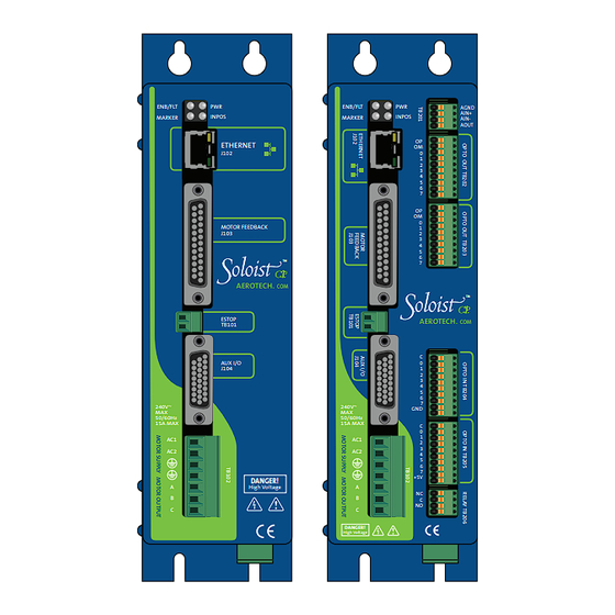
Aerotech Soloist CP Hardware Manual (118 pages)
network digital drive
Brand:
Aerotech
| Category:
Network Hardware
| Size: 1 MB
Table of Contents
Table of Contents
3
Table of Contents
4
List of Figures
5
List of Tables
7
Table of Contents
5
Table of Contents Soloist CP
5
EC Declaration of Conformity
9
Agency Approvals
10
Safety Procedures and Warnings
11
Quick Installation Guide
13
Chapter 1: Introduction
15
Table 1-1: Feature Summary
16
Table 1-2: Accessories
17
Functional Diagram
18
Drive and Software Compatibility
19
Table 1-3: Soloist Drive and Software Compatibility
19
Electrical Specifications
20
Table 1-4: Electrical Specifications
20
System Power Requirements
21
Power Dissipation
22
Mechanical Design
23
Table 1-5: Physical Specifications
23
Table 1-6: Heat Sink Specifications
23
Environmental Specifications
24
Chapter 2: Installation and Configuration
25
Power Connections
25
Control Supply Connections (TB106)
26
Table 2-1: Control Supply AC Input Wiring
26
Table 2-2: Control Supply Mating Connector
26
Motor Supply Connections (TB102)
27
Table 2-3: Motor Supply Mating Connector
27
Transformer Options
28
Table 2-4: Nominal Motor Operating Voltages / Required AC Voltages
28
Table 2-5: Transformer Options
28
VDC Motor Power with a TV0.3-28-56-ST Transformer
29
VDC Motor Power with a TV0.3-28-56-ST Transformer
30
Volt DC Bus from 115 and 230 VAC Source
31
Control and Motor Power Wiring Using a TM3 or TM5 Transformer
34
Minimizing Conducted, Radiated, and System Noise
35
Table 2-6: Motor Supply Input Wiring
35
Table 2-7: UFM-ST Electrical Specifications
35
Motor Output Connections
36
Table 2-8: Motor Power Output Connections (TB102)
36
Table 2-9: Motor Power Output Mating Connector
36
Brushless Motor Connections
37
Table 2-10: Wire Colors for Aerotech Supplied Cables (Brushless)
37
Powered Motor Phasing
38
Encoder and Hall Signal Diagnostics
39
Unpowered Motor and Feedback Phasing
40
Hall Phasing with Oscilloscope
41
Brushless Motor Phasing Goal
42
DC Brush Motor Connections
43
Table 2-11: Wire Colors for Aerotech Supplied Cables (DC Brush)
43
DC Brush Motor Phasing
44
Stepper Motor Connections
45
Table 2-12: Wire Colors for Aerotech Supplied Cables (Stepper)
45
Stepper Motor Phasing
46
Motor Feedback Connections (J103)
47
Table 2-13: Motor Feedback Connector Pin Assignment (J103)
47
Encoder Interface (J103)
48
Table 2-14: Encoder Interface Pin Assignment
48
Line Driver Encoder (Standard)
49
Endat Encoder Interface (J103)
50
Resolute Encoder Interface (J103)
51
Analog Encoder Interface
52
Table 2-15: Analog Encoder Specifications
52
Analog Encoder Interface (J103)
53
Encoder Phasing
54
Position Feedback in the Diagnostic Display
55
Hall-Effect Interface (J103)
56
Table 2-16: Hall-Effect Feedback Interface Pin Assignment (J103)
56
Table 2-17: Hall-Effect Feedback Interface Pin Assignment (J103)
57
Thermistor Interface (J103)
57
Encoder Fault Interface (J103)
58
Table 2-18: Encoder Fault Interface Pin Assignment (J103)
58
End of Travel Limit Input Interface (J103)
59
Table 2-19: End of Travel Limit Input Interface Pin Assignment (J103)
59
End of Travel Limit Interface Input (J103)
60
End of Travel Limit Phasing
61
Brake Output (J103)
62
Table 2-20: Brake Output Pin Assignment (J103)
62
Emergency Stop Sense Input (TB101)
63
Table 2-21: Electrical Noise Suppression Devices
63
Table 2-22: Electrical Noise Suppression Devices
63
Table 2-23: TB101 Mating Connector
63
Table 2-24: Typical ESTOP Relay Ratings
64
Typical ESTOP Interface
64
Auxiliary I/O Connector (J104)
65
Table 2-25: Auxiliary I/O Connector Pin Assignment (J104)
65
Auxiliary Encoder Channel (J104)
66
Table 2-26: Auxiliary Encoder Channel Pin Assignment (J104)
66
Auxiliary Encoder Channel (J104)
67
Position Synchronized Output (Pso)/Laser Firing (J104)
68
Table 2-27: PSO Output Pin Assignment (J104)
68
Table 2-28: PSO Output Sources
68
PSO Interface
69
Opto-Isolated Outputs (J104)
70
Table 2-29: Port 0 Digital Output Connector Pin Assignment (J104)
70
Table 2-30: Digital Output Specifications
70
Outputs Connected in Current Sinking Mode (J104)
71
Opto-Isolated Inputs (J104)
72
Table 2-31: Port 0 Digital Input Connector Pin Assignment (J104)
72
Table 2-32: PS2806-4 Opto-Device Specifications
72
Inputs Connected in Current Sinking Mode (J104)
73
High Speed User Inputs 4-5 (J104)
74
Table 2-33: Port 0 High Speed Digital Input Connector Pin Assignment (J104)
74
Table 2-34: Input Voltage Jumper Configuration
74
Analog Output 0 (J104)
75
Table 2-35: Analog Output Connector Pin Assignment (J104)
75
Analog Input 0 (J104)
76
Table 2-36: Analog Input Connector Pin Assignment (J104)
76
Brake Power Supply (TB103)
77
Table 2-37: Brake Output Connector Pin Assignment (TB103)
77
Table 2-38: Mating Connector (TB103)
77
Table 2-39: Brake Output Connector Pin Assignment (J103)
77
Brake Connected to J103
78
Brake Connected to TB103
79
Solid State Relay Specifications (TB103)
80
Table 2-40: Relay Specifications
80
Interface (TB103)
81
Connector Pin Assignment (TB103)
81
Port Connector Mating Connector (TB103)
81
EXTSHUNT Option (TB104)
82
Table 2-43: Recommended Shunt Resistors and Wire Gauge
82
Table 2-44: External Shunt Mating Connector
82
Table 2-45: Maximum Storage Energy
83
PC Configuration and Operation Information
85
Chapter 3: -I/O Expansion Board
87
Analog Output (TB201)
88
Analog Input (TB201)
89
Opto-Isolated Inputs (TB204, TB205)
90
Opto-Isolated Outputs (TB202, TB203)
93
Figure 3-7: Opto-Isolated Outputs (-IO Board)
94
Table 3-14: Output Specifications (TB202, TB203)
95
User Power (TB204, TB205)
97
Brake / Mechanical Relay (TB206)
98
Brake Configuration Jumpers
98
Mechanical Relay Specifications
98
Brake / Mechanical Relay Interface Connector
99
Figure 3-11: Brake Connected to TB206
100
Chapter 4: Standard Interconnection Cables
101
Joystick Interface
102
Table 4-2: Cable Part Numbers
104
Handwheel Interface
105
Chapter 5: Maintenance
107
Control Board
108
Table 5-2: Control Board Jumper Configuration
109
Preventative Maintenance
110
Appendix A: Warranty and Field Service
111
Appendix B: Revision History
113
Index
115
Advertisement
Advertisement
Related Products
Aerotech Soloist CL
Aerotech Soloist CL 10
Aerotech Soloist CP Series
Aerotech Soloist MP
Aerotech Soloist MP Series
Aerotech SOLOIST10
Aerotech SOLOIST20
Aerotech SOLOIST30-S
Aerotech SOLOIST30
Aerotech Soloist HPe 10
Aerotech Categories
Industrial Equipment
DC Drives
Controller
Engine
Amplifier
More Aerotech Manuals
Login
Sign In
OR
Sign in with Facebook
Sign in with Google
Upload manual
Upload from disk
Upload from URL