Aerotech APR100DR-145 Manuals
Manuals and User Guides for Aerotech APR100DR-145. We have 1 Aerotech APR100DR-145 manual available for free PDF download: Hardware Manual
Aerotech APR100DR-145 Hardware Manual (54 pages)
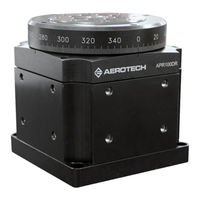
High-Precision Mechanical Bearing Rotary Stage
Brand: Aerotech
|
Category: Controller
|
Size: 6.1 MB
Table of Contents
Advertisement