Sign In
Upload
Manuals
Brands
ADVANTEST Manuals
Laser Level
R3273
ADVANTEST R3273 Manuals
Manuals and User Guides for ADVANTEST R3273. We have
4
ADVANTEST R3273 manuals available for free PDF download: Operation Manual
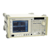
ADVANTEST R3273 Operation Manual (253 pages)
R3267 Series OPT62 3GPP Measurement Option
Brand:
ADVANTEST
| Category:
Measuring Instruments
| Size: 4 MB
Table of Contents
Safety Summary
2
Environmental Conditions
5
Preface
7
Table of Contents
8
1 Introduction
15
Product Overview
15
Accessories
15
Self Test Function
15
About Calibration
15
Explanation of the Connectors
16
2 Measurement Examples
17
Measuring the BTS 3GPP Signals
17
Measuring the Slot
17
Setup for the Measurement of the 3GPP Signal
17
3GPP Signal's Spectrum
18
STD-Measurement Parameter Set Dialog Box
18
Parameter Setup [SLOT/DOWNLINK] Dialog Box
19
Measurement Result of 3GPP Signal
21
Setup for the Measurement of the 3GPP Signal
22
3GPP Signal's Spectrum
22
Parameter Setup [FRAME/DOWNLINK] Dialog Box
23
Measuring the MS 3GPP Signal
25
Measuring the Slot
25
Setup for the Measurement of the 3GPP Signal
25
3GPP Signal's Spectrum
26
Parameter Setup [SLOT/UPLINK] Dialog Box
27
Measurement Result of 3GPP Signal (UPLINK Mode)
28
Measuring of the Frame
29
Setup for the Measurement of the 3GPP Signal
29
3GPP Signal's Spectrum
29
Parameter Setup [FRAME/UPLINK] Dialog Box
30
Graphical Display of 3GPP Measurements
32
Graph Display (When Meas Mode Set to FRAME and Link Set to DOWNLINK)
33
Variation over Time in the Code Domain Power Coefficient
34
Eye Pattern
35
Eye Pattern (Dual Screen Display)
36
Measuring a QPSK Signal
37
Setup for the Measurement of the QPSK Signal
37
QPSK Signal's Spectrum
37
Parameter Setup Dialog Box
38
QPSK Signal Measurement Result
39
Power Vs Time
40
Measuring Power Variations Using the External Trigger
40
Setup for the Measurement of the Power Vs Time
40
3GPP Signal Spectrum under Control of Transmission Power
41
3GPP Signal Spectrum
41
Power Vs Time Parameter Setup Dialog Box
42
Measurement Result of Power Vs Time
42
Measuring Power Variations Using the if Trigger
43
Setup for the Measurement of the Power Vs Time
43
3GPP Signal Spectrum under Control of Transmission Power
44
Time & FFT Parameter Setup Dialog Box
45
Power Vs Time Parameter Setup Dialog Box
46
CCDF Measurement
47
Setup for CCDF Measurement
47
3GPP Signal Spectrum under Control of Transmission Power
48
CCDF Parameter Setup Dialog Box
48
CCDF Measurement Result
49
CCDF Measurement Result (Trace Write ON)
50
Measuring Primary CPICH Power
51
Setup for Primary CPICH Power Measurement
51
STD Measurement Parameter Set Dialog Box
52
Parameter Setup Dialog Box
53
P-CPICH Power Measurement Results
53
Menu Index
55
3 Reference
55
Menu Map
61
Functional Description
80
Switching Communication Systems
81
Communication Systems Dialog Box
81
T-Domain
82
Power (T-Domain)
82
Trigger Setup Dialog Box
82
Parameter Setup Dialog Box
84
3.3.2.2 ON/OFF Ratio
85
Trigger Setup Dialog Box
85
Parameter Setup Dialog Box
87
Spurious (T-Domain)
88
Trigger Setup Dialog Box
88
Parameter Setup Dialog Box
89
F-Domain
91
Power (F-Domain)
91
Trigger Setup Dialog Box
91
Detector Dialog Box
92
Parameter Setup Dialog Box
93
3.3.3.2 Obw
94
Parameter Setup Dialog Box
95
3.3.3.3 Due to Transient
96
Parameter Setup Dialog Box
97
3.3.3.4 Due to Modulation
99
Trigger Setup Dialog Box
99
Detector Dialog Box
100
Parameter Setup Dialog Box
101
Inband Spurious (1)
103
Parameter Setup Dialog Box
104
Inband Spurious (2)
106
Parameter Setup Dialog Box
107
3.3.3.7 Outband Spurious
109
Parameter Setup Dialog Box
110
Modulation
111
3.3.4.1 3Gpp
111
Selecting the Unit of the Graph Horizontal Axis (for Channel Number)
112
Graph Type of Analysis Dialog Box
113
Constellation
114
Graph Type of Analysis Dialog Box
114
3GPP User Channel Setting Dialog Box
117
Parameter Setup [SLOT/DOWNLINK] Dialog Box
117
Explanation Diagram of MEAS Unit
120
Parameter Setup [FRAME/DOWNLINK] Dialog Box
121
Explanation Diagram of MEAS Slots
123
Parameter Setup [SLOT/UPLINK] Dialog Box
124
Explanation Diagram of MEAS Unit
126
Parameter Setup [FRAME/UPLINK] Dialog Box
127
Examination Diagram of Meas Slots
128
3.3.4.2 Qpsk
130
Graphic Type of Analysis Dialog Box
130
QPSK Measurement Parameter Set Dialog Box
131
Limit Setup Dialog Box
132
3.3.4.3 Power
133
3.3.4.3.1 Tx Power
133
Parameter Setup Dialog Box
133
3.3.4.3.2 Power Vs Time
134
Scale Setup Dialog Box
134
Parameter Setup Dialog Box
135
Marker Setup Dialog Box
136
3.3.4.3.3 Ccdf
137
Template Setup Dialog Box
137
Scale Setup Dialog Box
137
3.3.4.3.4 P-CPICH Power
138
Parameter Setup Dialog Box
138
Parameter Setup Dialog Box
139
3.3.4.4 Time & FFT
140
Select Type Dialog Box
140
Parameter Setup Dialog Box
140
3.3.4.5 Std
141
STD Measurement Parameter Setup Dialog Box
141
4 Remote Control
144
GPIB Command Index
153
GPIB Command Codes
153
Operating Mode
153
ATT Key (Attenuator)
153
COPY Key (Hard Copy)
153
COUPLE Key (Couple Function)
154
FREQ Key (Frequency)
154
LEVEL Key (Reference Level)
154
MKR Key (Marker)
155
PRESET Key (Initialization)
155
RCL Key (Recall)
155
SAVE Key (Save)
156
SPAN Key (Frequency Span)
156
TRANSIENT Key
185
Numeric Keys/Step Keys/Data Knob/Unit Keys (Entering Data)
206
Miscellaneous
207
5 Technical Information
209
Template Edit Function
209
Template Setting in the T-Domain Measuring Mode
209
Template to be Set
209
Template Settings
210
Template Shifted Using the Shift y Function
210
Template Setting in the F-Domain Measuring Mode
211
Template with the Set Values
211
Template with Margin Delta
211
Measurement Parameter Settings in Due to Transient, Due to Modulation and Inband Spurious
212
Marker Edit Function
212
Example of Marker Edit Setting
212
Measurement Results Using Due to Modulation, Due to Transient Inband Inbinband Spurious Modes
213
Example of Marker Edit Setting
213
Example of Peak Marker y Delta
213
Mag Error (Magnitude Error)
215
Error Vector Magnitude)
216
Mag Error, Phase Error, E.V.M
216
Waveform Quality
217
About a Code Domain Power Coefficient
217
About the Carrier Frequency Error of QPSK
217
Block Diagram
218
6 Performance Verification Test(3Gpp)
219
General
219
Performance Verification Items
219
Down Link Measurement in IQ Input
219
Test Equipment
220
Equipment List
220
7 Specifications
220
Specifications Required for Test Signals
221
Timing Chart
221
Calibration Cycle
222
Performance Verification Test Record Sheets
222
Performance Verification Procedure
222
Performance Verification Test Procedure
223
Down Link Measurement in RF Input
223
Setup of down Link Measurement (RF Input)
223
Up Link Measurement in RF Input
224
Setting of Measurement Parameters for down Link (RF Input)
224
Setup of up Link Measurement (RF Input)
225
QPSK Measurement in RF Input
226
Setting of Measurement Parameters for up Link (RF Input)
226
Setup of QPSK Measurement (RF Input)
227
Setting of Measurement Parameters for QPSK (RF Input)
227
Setup of down Link Measurement (IQ Input)
228
Setting of Measurement Parameters for down Link (IQ Input)
229
Setup of up Link Measurement (IQ Input)
230
Setting of Measurement Parameters for up Link (IQ Input)
230
Setup of QPSK Measurement (IQ Input)
231
Setting of Measurement Parameters for QPSK (IQ Input)
232
Setup of Simplified Performance Check
233
Setting of Measurement Parameters for QPSK (RF Input)
233
Appendix
243
Alphabetical Index
243
Limited Warranty
251
Advertisement
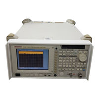
ADVANTEST R3273 Operation Manual (145 pages)
R3267 Series OPT08 Rx Control Option
Brand:
ADVANTEST
| Category:
Measuring Instruments
| Size: 2 MB
Table of Contents
Safety Summary
2
Environmental Conditions
5
Table of Contents
6
1 Outline of the Product
12
Outline
12
2 Before Starting
13
Confirmation of the Accessories
13
Standard Accessories
13
How to Connect to R3560, R3561 or R3562
14
Connecting the R3267 Series to R3560
14
Connection between R3267 Series and R3560 (Rear Panel)
14
Connection between R3267 Series and R3560 (Front Panel)
14
Connecting the R3267 Series to R3561 or R3562
15
Connection between R3267 Series and R3561 or R3562 (Rear Panel)
15
Serial Port Setting
16
Serial Port Selection Screen
16
3 How to Operate the R3560
17
Outline
17
Initial Screen
17
Initial Screen (R3560 Mode)
17
BER Measurement Screen
21
Dialog Box for BER Measurement Screen
21
Sens Measurement Screen
23
Dialog Box Screen for Sens Parameter Setting
23
SETUP Setting Screen
25
Timing of RF Signal Output Vs the Burst Trigger Input Signal
27
Time Defined According to the System Mode and the Rate
27
Effective Setting Condition in Burst Trigger Functions
27
SLOT Setting Screen
28
SACCH Settable Range
29
Scramble Pattern Setting Range
30
Setting Value of the Synchronization Word
31
Save Operation Screen
32
BER Measurement Screen (in Occurrence of Sync Error)
33
BER Measurement Connection
34
Initial Screen
36
Initial Screen (R3561 Mode)
36
Reference
37
General Dialog Screen
41
Frame a Dialog Box Screen
43
Channel Signals
44
Edit Menu Dialog Box Screen
45
Freq Para. Dialog Screen
46
Level Para. Dialog Screen
47
Other Screen
48
Clock Dialog Box Screen
48
Types of CDMA Frame Clock
49
Cal/Self Test Screen
50
Save/Recall Display Screen
51
Set Values When Preset
52
Initial Screen (for the R3562 Standard Configuration)
56
Initial Screen (with the R3562 OPT 65 Installed)
57
R3562 Control Main Screen (3GPP)
58
Menu Map
61
BER Parameter Setup Dialog Box
64
Functional Description
64
Clock/Timing Signal Parameter Setup Dialog Box
65
General Parameter Setup Dialog Box (for the Downlink)
66
General Parameter Setup Dialog Box (for the Uplink)
66
General Parameter Setup Dialog Box
66
STD Parameter Setup Dialog Box
70
DTCH/DCCH Parameter Setup Dialog Box (for the Downlink)
72
DTCH/DCCH Parameter Setup Dialog Box
72
DPCCH Parameter Setup Dialog Box (for the Uplink)
74
DTCH/DCCH Parameter Setup Dialog Box (for the Downlink)
75
Ext Trigger Parameter Setup Dialog Box
76
Frequency Parameter Setup Dialog Box
77
Level Parameter Setup Dialog Box
77
Clock/Timing Signal Parameter Setup Dialog Box
78
External I/Q Parameter Setup Dialog Box
79
Save Register List Dialog Box
80
Recall Register List Dialog Box
81
Connecting the DUT
82
Measurement Example
82
STD Parameter Setup Dialog Box
83
General Parameter Setup Dialog Box
84
BER Parameter Setup Dialog Box
85
Measurement Result on the Bit Error Rate
86
Initial Screen
87
6 How to Operate the R3562 Opt65
87
R3562 Control Main Screen (Cdma2000)
88
Reference
89
Menu Map
92
BER Parameter Setup Dialog Box
97
Functional Description
97
Clock/Timing Signal Parameter Setup Dialog Box
98
General Parameter Setup Dialog Box <When Reverse Is Set to RC 1 or RC 2>
99
General Parameter Setup Dialog Box <When Reverse Is Set to RC 3 or RC
101
General Parameter Setup Dialog Box <When Forward Is Set to RC 1 or RC
104
Example 1 Showing When the Output Level Supplemental Channel Is off
104
Example 2 Showing When the Output Level Supplemental Channel Is off
104
Example 1 Showing When the Output Level Supplemental Channel Is off
106
General Parameter Setup Dialog Box <When Forward Is Set to RC 3, RC4 or RC5
107
Example 2 Showing When the Output Level Supplemental Channel Is off
107
Example 1 Showing When the Output Level Supplemental Channel Is off
109
Example 2 Showing When the Output Level Supplemental Channel Is off
109
STD Parameter Setup Dialog Box
110
Frame Parameter Setup Dialog Box <When Reverse Is Set to RC
110
Frame Parameter Setup Dialog Box <When Reverse Is Set to RC
111
Frame Parameter Setup Dialog Box <When Reverse Is Set to RC
112
Frame Parameter Setup Dialog Box <When Forward Is Set to RC
113
Frame Parameter Setup Dialog Box <When Forward Is Set to RC2
113
Frame Parameter Setup Dialog Box <When Forward Is Set to RC3
115
Frame Parameter Setup Dialog Box <When Forward Is Set to RC4
115
Frame Parameter Setup Dialog Box <When Forward Is Set to RC5
116
Traffic Channel a Parameter Setup Dialog Box
117
PICH Parameter Setup Dialog Box
118
DCCH Parameter Setup Dialog Box
119
Traffic Channel a Parameter Setup Dialog Box
119
Traffic Channel B Parameter Setup Dialog Box
120
Traffic Channel C Parameter Setup Dialog Box
121
Traffic Channel a Parameter Setup Dialog Box
122
Traffic Channel B Parameter Setup Dialog Box
123
Traffic Channel C Parameter Setup Dialog Box
123
Traffic Channel a Parameter Setup Dialog Box
124
Traffic Channel B Parameter Setup Dialog Box
125
Traffic Channel C Parameter Setup Dialog Box
126
Frequency Parameter Setup Dialog Box
127
Level Parameter Setup Dialog Box
127
Clock/Timing Signal Parameter Setup Dialog Box
128
External I/Q Parameter Setup Dialog Box
130
Save Register List Dialog Box
131
Recall Register List Dialog Box
131
Connecting the DUT
132
Setup Example
132
STD Parameter Setup Dialog Box
133
Clock/Timing Signal Parameter Setup Dialog Box
133
Setup Example
133
Frame Parameter Setup Dialog Box <Reverse: RC1
135
Traffic Channel a Parameter Setup Dialog Box
136
Alphabetical Index
137
Limited Warranty
143
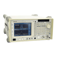
ADVANTEST R3273 Operation Manual (105 pages)
Spectrum Analyzer
Brand:
ADVANTEST
| Category:
Measuring Instruments
| Size: 0 MB
Table of Contents
Table of Contents
7
Performance Verification
11
Preparation
11
Instrument Required
12
Procedure
14
Frequency Reference Output Accuracy
14
Setup for Measuring a Frequency Reference Output Accuracy
15
Frequency Reference Output Accuracy (When the OPT21, OPT22 and OPT23 Are Installed)
16
Connections for Measuring the Frequency Reference Output Accuracy (When the OPT21, OPT22 and OPT23 Are Installed)
16
Accuracy of Frequency Readout and Frequency Counter
18
Setup for Measuring a Frequency Readout Accuracy and Frequency Counter
18
Frequency Span Setting at a Center Frequency of 2 Ghz
19
Frequency Span Accuracy
21
Setup for Measuring a Frequency Span Accuracy
21
Center/Span Frequencies for the R3267
22
Center/Span Frequencies for the R3273
23
Calibration Amplitude Accuracy
24
IF Gain Uncertainty
25
Setup for Measuring a if Gain Uncertainty
25
IF Gain Uncertainty Setting
27
RBW Setting
27
Input Attenuator Switching Accuracy
28
Setup for Measuring an Input Attenuator Accuracy
29
Input Attenuator Setting
30
Frequency Response
31
Setup for Measuring a Frequency Response
32
Scale Fidelity
36
Setup for Measuring a Scale Fidelity
36
HP8495H and HP3325B Settings
39
Settings on the HP3325B in Relation to the Reference Output Level
40
RBW Switching Uncertainty
41
RBW Switching Uncertainty Setting
42
RBW Accuracy and Selectivity
43
Db Band Width Setting
44
Db Band Width Setting
45
Noise Sidebands
46
Setup for Measuring a Noise Sidebands
47
Offset Setting at a Center Frequency of 1 Ghz
48
Displayed Average Noise Level
49
Center Frequency Setting for Displayed Average Noise Level
51
Start and Stop Frequencies Setting
52
Residual FM
53
Setup for Measuring a Residual FM
53
Residual Response
56
Gain Compression
59
Setup for the Gain Compression
60
Second Harmonic Distortion
63
Setup for Measuring a Second Harmonics Distortion
64
Third Order Intermodulation Distortion
67
Setup for Measuring a Third Order Intermodulation Distortion
68
Image, Multiple and out of Band Responses (for the R3267/73)
72
Setup for Measuring a Image, Multiple, out of Band
72
Image, Multiple, out of Band Setting for the R3273
75
Image, Multiple, out of Band Setting for the R3267
76
Sweep Time Accuracy
78
Setup for Measuring a Sweep Time Accuracy
78
Sweep Time Setting
80
Performance Check Sheet
81
Frequency Reference Output Accuracy
81
Frequency Readout Accuracy and Frequency Counter Marker
81
Frequency Span Accuracy
82
Calibration Amplitude Accuracy
83
IF Gain Uncertainty
83
Frequency Response
86
Scale Fidelity
94
Resolution Bandwidth Switching
95
Resolution Bandwidth Accuracy and Selectivity
96
Noise Sidebands
96
Displayed Average Noise Level
97
Residual FM
97
Residual Response
97
Gain Compression
98
Second Harmonics Distortion
98
Third Order Intermodulation Distortion
98
Advertisement
ADVANTEST R3273 Operation Manual (34 pages)
R3267 Series OPT11 3GPP Level Calibration
Brand:
ADVANTEST
| Category:
Laser Level
| Size: 0 MB
Table of Contents
Table of Contents
6
1 Introduction
9
Product Description
9
Accessories
9
Precautions in Use
9
Calibration
10
2 Operation
11
3GPP Level Calibration Data and the Setting Conditions
11
Frequency Range for 3GPP Level Calibration Data and the Frequency
11
Setting Conditions Used for 3GPP Level Calibrations
11
Using 3GPP Level Calibration Data
12
Measurement Sample
13
3 Reference
15
Menu Index
15
Menu Map
16
Functional Description
16
4 Remote Programming
17
GPIB Command Index
17
GPIB Command Codes
18
3GPP Level Calibration (OPT11)
18
5 Performance Verification Test
19
General
19
Introduction
19
Test Equipment
19
Performance Verification Test Record Sheet
20
Equipment List
20
5.1.4 Performance Verification Procedure
21
Performance Verification Test Procedure
22
Level Calibration
22
Setup of Level Calibration Test
23
List for SG and PM Correction Data Setting
24
Setting of SG and R3267 Series
25
Performance Verification Test Record Sheet
26
6 Specifications
28
Appendix
29
A.1 Error Message List
29
Alphabetical Index
30
Advertisement
Related Products
ADVANTEST R3264
Advantest R3267 series
ADVANTEST R3261C
ADVANTEST R3261D
ADVANTEST R3261CN
ADVANTEST R3261DN
ADVANTEST R3755E
ADVANTEST R3172
ADVANTEST R3765BG
ADVANTEST R3765CG
ADVANTEST Categories
Measuring Instruments
Multimeter
Portable Generator
Recording Equipment
Laser Level
More ADVANTEST Manuals
Login
Sign In
OR
Sign in with Facebook
Sign in with Google
Upload manual
Upload from disk
Upload from URL