Sign In
Upload
Manuals
Brands
Advantest Manuals
Measuring Instruments
R3267 series
User Manuals: Advantest R3267 series Spectrum Analyzer
Manuals and User Guides for Advantest R3267 series Spectrum Analyzer. We have
5
Advantest R3267 series Spectrum Analyzer manuals available for free PDF download: Operation Manual
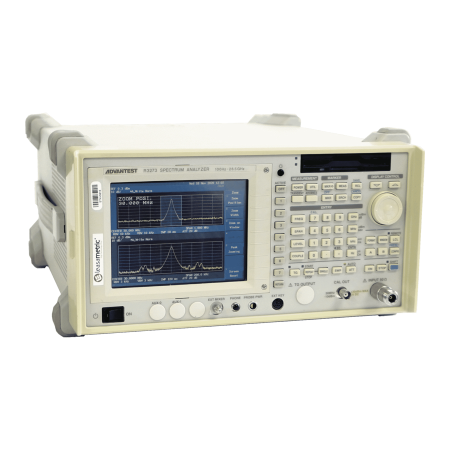
Advantest R3267 series Operation Manual (398 pages)
Spectrum Analyzer
Brand:
Advantest
| Category:
Measuring Instruments
| Size: 6 MB
Table of Contents
Safety Summary
2
Environmental Conditions
5
Table of Contents
12
1 Introduction
23
Standard Accessories List
24
Accessories
24
Power Cable Options
25
Operating Environment
26
Power Supply Specifications
27
Replacing the Power Fuse
28
Power Cable
29
Precautions in Use
30
Human Body
31
Floor in the Work Area
31
Benchboard
31
Connecting the Power Supply Cable
32
System Checkout
32
Start-Up Screen
33
Config Menu
33
Selftest Menu
34
Selftest Result
34
Removing the Display Filter
35
Cleaning, Storing and Transporting the R3267 Series
35
Storing
36
About Calibration
37
Front Panel
38
2 Operation
38
Display Section
39
Power Switch/Connector Section
40
Floppy Disk Drive Section
41
MEASUREMENT Section
41
MARKER Section
42
Save/Recall Section
42
DISPLAY CONTROL Section
43
ENTRY Section
44
REMOTE Section
45
Control Section
46
Option Section
46
Screen Annotation
47
Display Area Names
48
Rear Panel
49
Span Menu
51
Basic Operation
51
Soft Menu Configuration (CONFIG Key)
53
Displaying Spectrums and Operating the Markers
55
Factory Defaults
56
Calibration Output
56
Frequency Menu
57
Setting the Center Frequency
57
Setting Measurement Conditions
58
Peak Search
58
Frequency Difference between the Peak Point and a Point 3 Db Levels down
59
Frequency Difference between the Peak Point and a Point 60 Db Levels down
59
Measuring Frequency Using Counter
60
Setting Measurement Conditions
61
Frequency Counter Measurement
61
Frequency Counter Measurement (Resolution: 10 Hz)
62
Display Line and Measuring Window
63
The Display Line
64
Measuring the Values Relative to the Display Line
64
The Measuring Window
65
Correction Table
66
Entering Level Correction Data
66
Setting Measurement Conditions
67
Displaying the Correction Table
67
Entering Frequency Data
68
Showing a Trace Whose Level Is Corrected
68
Corrected Compensation Data
69
Setup for Measuring Two Signals Separately
70
Separating Two Signals
70
Two Superimposed Peaks
71
Two Discernible Peaks
71
Two Distinct Peaks Can Now be Seen
72
Setup for Verifying the Dynamic Range
73
Trace Prior to Changing the RBW
74
Trace after Changing the RBW
74
Trace after Changing the VBW
75
The Trace after Averaging
75
UNCAL Message
76
Measuring am Signal in Separate Screen Mode
76
Screen with UNCAL Message
77
UNCAL Message Removed
77
Zooming the Frequency Domain
78
Measuring am Signal in Separate Screen Mode
78
Displaying the Trace in Full Screen Mode
79
Displaying the Trace in Separate Screen Mode
79
Separate Screen Mode
79
Displaying the Magnified Lower Screen
80
2.2.10 Zooming the Time Domain
81
Measuring Burst Signal in Separate Screen Mode
81
Trace of a Burst Signal
82
Burst Signal in the Zero Span
83
Displaying the Trace in the Separate Screen Mode
83
Observing the Leading Edge in the Separate Screen Mode
84
Observing the Trailing Edge in Separate Screen Mode
84
2.2.11 Measurement Using the F/T Function
86
Trace of a Burst Signal
87
F/T Function Displayed in Separate Screen Mode
88
F/T Mode in Zoom Display
88
2.2.12 Measuring Dual Parameters
90
2.2.12.1 Measuring Dual Parameters in the Frequency Domain
90
Setup to Measure Dual Parameters
90
Displaying in Separate Screen Mode
91
Setting for the Upper Screen in Separate Screen Mode
92
Setting for the Lower Screen in Separate Screen Mode
92
Magnified Trace for the Lower Screen
93
2.2.12.2 Measuring Dual Parameters in the Time Domain
94
Upper Screen in Sync with the Trigger Signal
95
Displaying the Traces of 900 Mhz and 1800 Mhz in the Separate Screen Mode
96
Displaying the Trace of 1800 Mhz for the Lower Screen
97
2.2.13 Calibration
98
Calibration Items
98
2.2.13.1 Cal All
99
Cal Menu
99
2.2.13.2 Total Gain
100
2.2.13.3 Cal each Item
101
2.2.14 Pass/Fail Judgments Using the Limit Line Function
102
Editing the Limit Line
103
Setting Limit Line
103
Screen Displayed after Limit Line 1 Data Has Been Entered
104
Screen Displayed after Limit Line 2 Data Has Been Entered
104
Setting Limit Line PASS/FAIL
105
PASS/FAIL Result Using Limit Line
105
PASS/FAIL Result Using Limit Lines 1 and 2 ................................................................. 2-79 Judgment Result after the Offset Has Been Changed
106
Measurement Examples
108
Measuring Average Power of Digital Modulation Signal
108
Setup for the Average Power Measurement
108
Checking the Input Signal
110
Setting Measurement Conditions for Average Power Measurement
110
Result of an Average Power Measurement
111
Moving the Measurement Result
111
Measuring CDMA Wave's Total Power
112
Setup for Measuring the Total Power
112
Setting Conditions for the Total Power Measurement
114
Result of Total Power Measurement
114
Measuring the Power Density of Wide Band Digital Modulation Signal
115
Setup for Measuring the Total Power
115
Displaying the Measuring Window
117
Power Density Measurement
117
Measuring CDMA Channel Power
118
Setup for Measuring the Channel Power
118
Result of Channel Power Measurement
120
Measuring the Occupied Bandwidth (OBW)
121
Setup for Measuring the Occupied Bandwidth
121
OBW Measurement Results
123
Measuring Adjacent Channel Leakage Power (ACP)
124
2.3.6.1 Full Screen Mode
124
Setup Measuring Adjacent Channel Leakage Power
125
PDC Trace
126
CS/BS Setup Dialog Box
127
Root Nyquist Filter Dialog Box
128
ACP Measurement Display in Full Screen Mode
128
Measurement Using ACP GRAPH
129
ACP at the 100 Khz
129
2.3.6.2 SEPARATE Display
130
Setup Measuring Adjacent Channel Leakage Power
130
PHS Trace
131
CS/BS Setup Dialog Box
132
Measurement Result in ACP Separate Screen Mode
133
Measuring Burst Signals Using the Gated Sweep
134
Setup for Measuring a Burst Signal
134
Burst Signal Displayed in Split Screen Mode
135
Trigger Setup
135
Burst Signal by Use of the Gated Sweep (Separate Screen Mode)
136
Burst Signal by Use of the Gated Sweep (Full Screen Mode)
137
Measuring Burst Signals in the Time Domain
138
Setup for Measuring a Burst Wave Signal
138
Burst Signal in the Frequency Domain
139
Burst Signal in the Time Domain
139
Burst Signal in Synchronization with the Trigger Signal
140
Measuring Burst Signal Leading Edge
141
Measuring Burst Signal Trailing Edge
141
Harmonic Distortion Measurements
142
2.3.9.1 Using the Normal and Delta Markers
142
Setup for Measuring the Harmonic Distortion
142
Trace of Harmonics
143
Secondary Harmonics
144
Tertiary Harmonics
144
2.3.9.2 Using the Peak List
145
Setup for Measuring the Harmonic Distortion
145
Trace of Harmonics
146
Peak List Display
147
2.3.9.3 Using the Fixed Marker Function
148
Setup for Measuring the Harmonic Distortion
148
Trace of Harmonics
149
Secondary Harmonics
150
Tertiary Harmonics
150
2.3.10 Third Order Intermodulation Distortion
151
Setup for Measuring the Third Order Intermodulation Distortion
151
Third Order Intermodulation Distortion
152
Third Order Intermodulation Distortion (Peak Æ Ref)
152
Measurement Result of the Third Order Intermodulation Distortion
153
2.3.11 am Modulation Frequency and Modulation Factor of am Signals
154
Setup for Measuring am Signal
154
AM Signal with Low Modulation Factor
155
2.3.12 Measuring Frequency Deviation of FM Signals
157
Setup for Measuring FM Signal
157
Trace of an FM Signal
158
Measuring a Frequency Deviation
158
Modulation Frequency of the FM Signal
159
2.3.13 Measuring Modulation Index of FM Signals
160
Setup for Measuring Modulation Index
160
FM Signal with Low Modulation Index
161
2.3.14 Carrier Frequency and Power Measurements Using Pulsed RF Signals
162
Setup for Measuring Pulsed RF Signal
162
Spectrum of a Pulsed Signal
164
Measuring Peak Power
164
Measuring the Pulse Repetition Frequency
166
Expanded Functions
167
Saving/Recalling Measurement Conditions
167
2.4.1.1 Saving/Recalling Basic Measurement Conditions
167
Selecting Destination Device
168
Save Item Setup Dialog Box
168
File Saved
169
File Protection Enabled
170
Selected File
172
Read Data
172
File to be Deleted
173
File Already Deleted
173
2.4.1.2 Saving/Recalling OBW Measurement Conditions
174
2.4.1.3 Saving/Recalling ACP Measurement Conditions
174
Saving Screen Data
175
File Dialog Box
176
Obtaining a Hard Copy of Screen Data
177
Recommended Printers
177
Printer Dialog Box
178
Formatting Media
179
Floppy Disk Write Protection
179
Formatting the Memory Card (Option)
180
Media Menu
180
Slots in the Memory Card Drive
181
Setting Date and Time
183
Date/Time Dialog Box
183
Setting the Screen Label
184
Dialog Box Used to Enter Labels
184
Displaying the Screen Label
185
Menu Index
186
3 Reference
186
Menu Map
192
Functional Description
205
A Key (Trace A)
205
ATT Key (Attenuator)
209
B Key (Trace B)
210
CAL Key (Calibration)
213
CONFIG Key (Configuration)
215
COPY Key (Copy)
221
COUPLE Key (Couple Function)
222
FORMAT Key (Display Format)
225
FREQ Key (Frequency)
230
FREQ Key (Frequency)
231
LCL Key (GPIB Remote Control)
233
LEVEL Key (Level)
234
MEAS Key (Measurement)
236
MKR Key (Marker)
238
MKR Key
241
OFF Key (Marker Off)
242
POWER Key (Power Measurement)
243
PRESET Key (Initialization)
247
RCL Key (Data Readout)
248
REPEAT Key (Continuous Sweep)
249
SAVE Key (Saving Data)
250
SINGLE Key (Single Sweep)
254
SPAN Key (Frequency Span)
255
SRCH Key (Peak Search)
256
SWP Key (Sweep Time)
259
UTIL Key (Utility)
262
3.3.26 WINDOW Key
268
List of Settings
270
Set Resolution
270
Set Values for RBW, VBW and Sweep-Time
270
Center Frequency Set Resolution Vs. Frequency Span
270
Values for RBW, VBW and Sweep-Time (Using AUTO)
270
Factory Defaults
271
Defaults Configuration Values
271
Default Settings
271
Parameters Range
274
4 Principle of Measurement
275
Input Saturation
275
Measuring Adjacent Channel Leakage Power (ACP)
277
Differences between Full Screen and Separate Screen Operation Processes
277
Root Nyquist Filter
280
Operation of the Gated Sweep
281
Generating the Internal Gate Signal
282
Eye Opening Calculation
283
Calculation Using no Measurement Window
283
Eye Opening Ratio Calculation (Using no Measurement Window)
283
Calculation Using the Measurement Window
284
Eye Opening Calculation (Using the Measurement Window)
284
Phase Jitter Measurement
285
Additional Functions
285
RMS Phase Jitter Measurement Method
285
GPIB Command Index
286
5 Remote Programming
286
GPIB Remote Programming
292
Gpib
292
GPIB Setup
293
5.2.3 GPIB Interface Functions
294
Responses to Interface Messages
295
Message Exchange Protocol
296
Command Syntax
297
Data Formats
298
Status Bytes
299
Arrangement of the Three Status Registers
300
Details of the Three Status Registers
301
Structure of the Status Byte Register
303
GPIB Command Codes
306
A Key/B Key (Trace A/Trace B)
306
ATT Key (Attenuator)
308
CAL Key (Calibration)
309
CONFIG Key (Configuration)
310
COUPLE Key (Couple Function)
311
FORMAT Key (Display Format)
312
FREQ Key (Frequency)
314
LEVEL Key
315
MEAS Key
316
POWER Key (Power Measurement)
319
MKR → Key (Maker →)
319
PRESET Key (Initialization)
320
RCL Key (Reading Data)
320
SPAN Key (Frequency Span)
321
SAVE Key (Saving Data)
321
SRCH Key (Peak Search)
322
SWP/SINGLE Key (Sweep Time)
323
UTIL Key (Utility)
324
WINDOW Key (Window)
327
Numeric Keys/Step Keys/Data Knob/Unit Keys (Entering Data)
328
Miscellaneous
329
5.2.10 Example Programs
330
5.2.10.1 Sample Programs for Setting or Reading Measurement Conditions
330
5.2.10.2 Sample Programs for Reading Data
332
5.2.10.3 Sample Programs for Inputting or Outputting Trace Data
337
Relationship between Screen Graticule and Trace Data
337
Trace Accuracy Specification Codes
337
I/O Formati
338
5.2.10.4 Program Examples Using the Status Byte
341
Remote Control Function
344
GPIB and RS-232 Compatibility
344
Features of RS-232 Remote Control
344
Parameter Setup Window
344
Parameter Setup
344
Interface Connection
345
Connection between the Controller and the Analyzer
345
Data Format
346
Cable Wiring Diagram
346
Differences between RS-232 and GPIB
347
Panel Control
347
Remote Control Usage Examples
348
6 Specifications
349
R3264 Specifications
349
R3267 Specifications
355
R3273 Specifications
362
Specifications for the Memory Card (Option)
369
Appendix
370
A.1 before Contacting with a Problem
370
A.2 Error Message
372
A.3 Glossary
378
Bandwidth Selectivity
378
Bandwidth Switching Uncertainty
379
IF Gain Uncertainty
379
Noise Sidebands
380
Occupied Bandwidth
381
Resolution Bandwidth
382
Spurious Response
383
Limited Warranty
396
Advertisement
ADVANTEST R3267 series Operation Manual (253 pages)
R3267 Series OPT62 3GPP Measurement Option
Brand:
ADVANTEST
| Category:
Measuring Instruments
| Size: 4 MB
Table of Contents
Safety Summary
2
Environmental Conditions
5
Preface
7
Table of Contents
8
1 Introduction
15
Product Overview
15
Accessories
15
Self Test Function
15
About Calibration
15
Explanation of the Connectors
16
2 Measurement Examples
17
Measuring the BTS 3GPP Signals
17
Measuring the Slot
17
Setup for the Measurement of the 3GPP Signal
17
3GPP Signal's Spectrum
18
STD-Measurement Parameter Set Dialog Box
18
Parameter Setup [SLOT/DOWNLINK] Dialog Box
19
Measurement Result of 3GPP Signal
21
Setup for the Measurement of the 3GPP Signal
22
3GPP Signal's Spectrum
22
Parameter Setup [FRAME/DOWNLINK] Dialog Box
23
Measuring the MS 3GPP Signal
25
Measuring the Slot
25
Setup for the Measurement of the 3GPP Signal
25
3GPP Signal's Spectrum
26
Parameter Setup [SLOT/UPLINK] Dialog Box
27
Measurement Result of 3GPP Signal (UPLINK Mode)
28
Measuring of the Frame
29
Setup for the Measurement of the 3GPP Signal
29
3GPP Signal's Spectrum
29
Parameter Setup [FRAME/UPLINK] Dialog Box
30
Graphical Display of 3GPP Measurements
32
Graph Display (When Meas Mode Set to FRAME and Link Set to DOWNLINK)
33
Variation over Time in the Code Domain Power Coefficient
34
Eye Pattern
35
Eye Pattern (Dual Screen Display)
36
Measuring a QPSK Signal
37
Setup for the Measurement of the QPSK Signal
37
QPSK Signal's Spectrum
37
Parameter Setup Dialog Box
38
QPSK Signal Measurement Result
39
Power Vs Time
40
Measuring Power Variations Using the External Trigger
40
Setup for the Measurement of the Power Vs Time
40
3GPP Signal Spectrum under Control of Transmission Power
41
3GPP Signal Spectrum
41
Power Vs Time Parameter Setup Dialog Box
42
Measurement Result of Power Vs Time
42
Measuring Power Variations Using the if Trigger
43
Setup for the Measurement of the Power Vs Time
43
3GPP Signal Spectrum under Control of Transmission Power
44
Time & FFT Parameter Setup Dialog Box
45
Power Vs Time Parameter Setup Dialog Box
46
CCDF Measurement
47
Setup for CCDF Measurement
47
3GPP Signal Spectrum under Control of Transmission Power
48
CCDF Parameter Setup Dialog Box
48
CCDF Measurement Result
49
CCDF Measurement Result (Trace Write ON)
50
Measuring Primary CPICH Power
51
Setup for Primary CPICH Power Measurement
51
STD Measurement Parameter Set Dialog Box
52
Parameter Setup Dialog Box
53
P-CPICH Power Measurement Results
53
Menu Index
55
3 Reference
55
Menu Map
61
Functional Description
80
Switching Communication Systems
81
Communication Systems Dialog Box
81
T-Domain
82
Power (T-Domain)
82
Trigger Setup Dialog Box
82
Parameter Setup Dialog Box
84
3.3.2.2 ON/OFF Ratio
85
Trigger Setup Dialog Box
85
Parameter Setup Dialog Box
87
Spurious (T-Domain)
88
Trigger Setup Dialog Box
88
Parameter Setup Dialog Box
89
F-Domain
91
Power (F-Domain)
91
Trigger Setup Dialog Box
91
Detector Dialog Box
92
Parameter Setup Dialog Box
93
3.3.3.2 Obw
94
Parameter Setup Dialog Box
95
3.3.3.3 Due to Transient
96
Parameter Setup Dialog Box
97
3.3.3.4 Due to Modulation
99
Trigger Setup Dialog Box
99
Detector Dialog Box
100
Parameter Setup Dialog Box
101
Inband Spurious (1)
103
Parameter Setup Dialog Box
104
Inband Spurious (2)
106
Parameter Setup Dialog Box
107
3.3.3.7 Outband Spurious
109
Parameter Setup Dialog Box
110
Modulation
111
3.3.4.1 3Gpp
111
Selecting the Unit of the Graph Horizontal Axis (for Channel Number)
112
Graph Type of Analysis Dialog Box
113
Constellation
114
Graph Type of Analysis Dialog Box
114
3GPP User Channel Setting Dialog Box
117
Parameter Setup [SLOT/DOWNLINK] Dialog Box
117
Explanation Diagram of MEAS Unit
120
Parameter Setup [FRAME/DOWNLINK] Dialog Box
121
Explanation Diagram of MEAS Slots
123
Parameter Setup [SLOT/UPLINK] Dialog Box
124
Explanation Diagram of MEAS Unit
126
Parameter Setup [FRAME/UPLINK] Dialog Box
127
Examination Diagram of Meas Slots
128
3.3.4.2 Qpsk
130
Graphic Type of Analysis Dialog Box
130
QPSK Measurement Parameter Set Dialog Box
131
Limit Setup Dialog Box
132
3.3.4.3 Power
133
3.3.4.3.1 Tx Power
133
Parameter Setup Dialog Box
133
3.3.4.3.2 Power Vs Time
134
Scale Setup Dialog Box
134
Parameter Setup Dialog Box
135
Marker Setup Dialog Box
136
3.3.4.3.3 Ccdf
137
Template Setup Dialog Box
137
Scale Setup Dialog Box
137
3.3.4.3.4 P-CPICH Power
138
Parameter Setup Dialog Box
138
Parameter Setup Dialog Box
139
3.3.4.4 Time & FFT
140
Select Type Dialog Box
140
Parameter Setup Dialog Box
140
3.3.4.5 Std
141
STD Measurement Parameter Setup Dialog Box
141
4 Remote Control
144
GPIB Command Index
153
GPIB Command Codes
153
Operating Mode
153
ATT Key (Attenuator)
153
COPY Key (Hard Copy)
153
COUPLE Key (Couple Function)
154
FREQ Key (Frequency)
154
LEVEL Key (Reference Level)
154
MKR Key (Marker)
155
PRESET Key (Initialization)
155
RCL Key (Recall)
155
SAVE Key (Save)
156
SPAN Key (Frequency Span)
156
TRANSIENT Key
185
Numeric Keys/Step Keys/Data Knob/Unit Keys (Entering Data)
206
Miscellaneous
207
5 Technical Information
209
Template Edit Function
209
Template Setting in the T-Domain Measuring Mode
209
Template to be Set
209
Template Settings
210
Template Shifted Using the Shift y Function
210
Template Setting in the F-Domain Measuring Mode
211
Template with the Set Values
211
Template with Margin Delta
211
Measurement Parameter Settings in Due to Transient, Due to Modulation and Inband Spurious
212
Marker Edit Function
212
Example of Marker Edit Setting
212
Measurement Results Using Due to Modulation, Due to Transient Inband Inbinband Spurious Modes
213
Example of Marker Edit Setting
213
Example of Peak Marker y Delta
213
Mag Error (Magnitude Error)
215
Error Vector Magnitude)
216
Mag Error, Phase Error, E.V.M
216
Waveform Quality
217
About a Code Domain Power Coefficient
217
About the Carrier Frequency Error of QPSK
217
Block Diagram
218
6 Performance Verification Test(3Gpp)
219
General
219
Performance Verification Items
219
Down Link Measurement in IQ Input
219
Test Equipment
220
Equipment List
220
7 Specifications
220
Specifications Required for Test Signals
221
Timing Chart
221
Calibration Cycle
222
Performance Verification Test Record Sheets
222
Performance Verification Procedure
222
Performance Verification Test Procedure
223
Down Link Measurement in RF Input
223
Setup of down Link Measurement (RF Input)
223
Up Link Measurement in RF Input
224
Setting of Measurement Parameters for down Link (RF Input)
224
Setup of up Link Measurement (RF Input)
225
QPSK Measurement in RF Input
226
Setting of Measurement Parameters for up Link (RF Input)
226
Setup of QPSK Measurement (RF Input)
227
Setting of Measurement Parameters for QPSK (RF Input)
227
Setup of down Link Measurement (IQ Input)
228
Setting of Measurement Parameters for down Link (IQ Input)
229
Setup of up Link Measurement (IQ Input)
230
Setting of Measurement Parameters for up Link (IQ Input)
230
Setup of QPSK Measurement (IQ Input)
231
Setting of Measurement Parameters for QPSK (IQ Input)
232
Setup of Simplified Performance Check
233
Setting of Measurement Parameters for QPSK (RF Input)
233
Appendix
243
Alphabetical Index
243
Limited Warranty
251
ADVANTEST R3267 series Operation Manual (145 pages)
R3267 Series OPT08 Rx Control Option
Brand:
ADVANTEST
| Category:
Measuring Instruments
| Size: 2 MB
Table of Contents
Safety Summary
2
Environmental Conditions
5
Table of Contents
6
1 Outline of the Product
12
Outline
12
2 Before Starting
13
Confirmation of the Accessories
13
Standard Accessories
13
How to Connect to R3560, R3561 or R3562
14
Connecting the R3267 Series to R3560
14
Connection between R3267 Series and R3560 (Rear Panel)
14
Connection between R3267 Series and R3560 (Front Panel)
14
Connecting the R3267 Series to R3561 or R3562
15
Connection between R3267 Series and R3561 or R3562 (Rear Panel)
15
Serial Port Setting
16
Serial Port Selection Screen
16
3 How to Operate the R3560
17
Outline
17
Initial Screen
17
Initial Screen (R3560 Mode)
17
BER Measurement Screen
21
Dialog Box for BER Measurement Screen
21
Sens Measurement Screen
23
Dialog Box Screen for Sens Parameter Setting
23
SETUP Setting Screen
25
Timing of RF Signal Output Vs the Burst Trigger Input Signal
27
Time Defined According to the System Mode and the Rate
27
Effective Setting Condition in Burst Trigger Functions
27
SLOT Setting Screen
28
SACCH Settable Range
29
Scramble Pattern Setting Range
30
Setting Value of the Synchronization Word
31
Save Operation Screen
32
BER Measurement Screen (in Occurrence of Sync Error)
33
BER Measurement Connection
34
Initial Screen
36
Initial Screen (R3561 Mode)
36
Reference
37
General Dialog Screen
41
Frame a Dialog Box Screen
43
Channel Signals
44
Edit Menu Dialog Box Screen
45
Freq Para. Dialog Screen
46
Level Para. Dialog Screen
47
Other Screen
48
Clock Dialog Box Screen
48
Types of CDMA Frame Clock
49
Cal/Self Test Screen
50
Save/Recall Display Screen
51
Set Values When Preset
52
Initial Screen (for the R3562 Standard Configuration)
56
Initial Screen (with the R3562 OPT 65 Installed)
57
R3562 Control Main Screen (3GPP)
58
Menu Map
61
BER Parameter Setup Dialog Box
64
Functional Description
64
Clock/Timing Signal Parameter Setup Dialog Box
65
General Parameter Setup Dialog Box (for the Downlink)
66
General Parameter Setup Dialog Box (for the Uplink)
66
General Parameter Setup Dialog Box
66
STD Parameter Setup Dialog Box
70
DTCH/DCCH Parameter Setup Dialog Box (for the Downlink)
72
DTCH/DCCH Parameter Setup Dialog Box
72
DPCCH Parameter Setup Dialog Box (for the Uplink)
74
DTCH/DCCH Parameter Setup Dialog Box (for the Downlink)
75
Ext Trigger Parameter Setup Dialog Box
76
Frequency Parameter Setup Dialog Box
77
Level Parameter Setup Dialog Box
77
Clock/Timing Signal Parameter Setup Dialog Box
78
External I/Q Parameter Setup Dialog Box
79
Save Register List Dialog Box
80
Recall Register List Dialog Box
81
Connecting the DUT
82
Measurement Example
82
STD Parameter Setup Dialog Box
83
General Parameter Setup Dialog Box
84
BER Parameter Setup Dialog Box
85
Measurement Result on the Bit Error Rate
86
Initial Screen
87
6 How to Operate the R3562 Opt65
87
R3562 Control Main Screen (Cdma2000)
88
Reference
89
Menu Map
92
BER Parameter Setup Dialog Box
97
Functional Description
97
Clock/Timing Signal Parameter Setup Dialog Box
98
General Parameter Setup Dialog Box <When Reverse Is Set to RC 1 or RC 2>
99
General Parameter Setup Dialog Box <When Reverse Is Set to RC 3 or RC
101
General Parameter Setup Dialog Box <When Forward Is Set to RC 1 or RC
104
Example 1 Showing When the Output Level Supplemental Channel Is off
104
Example 2 Showing When the Output Level Supplemental Channel Is off
104
Example 1 Showing When the Output Level Supplemental Channel Is off
106
General Parameter Setup Dialog Box <When Forward Is Set to RC 3, RC4 or RC5
107
Example 2 Showing When the Output Level Supplemental Channel Is off
107
Example 1 Showing When the Output Level Supplemental Channel Is off
109
Example 2 Showing When the Output Level Supplemental Channel Is off
109
STD Parameter Setup Dialog Box
110
Frame Parameter Setup Dialog Box <When Reverse Is Set to RC
110
Frame Parameter Setup Dialog Box <When Reverse Is Set to RC
111
Frame Parameter Setup Dialog Box <When Reverse Is Set to RC
112
Frame Parameter Setup Dialog Box <When Forward Is Set to RC
113
Frame Parameter Setup Dialog Box <When Forward Is Set to RC2
113
Frame Parameter Setup Dialog Box <When Forward Is Set to RC3
115
Frame Parameter Setup Dialog Box <When Forward Is Set to RC4
115
Frame Parameter Setup Dialog Box <When Forward Is Set to RC5
116
Traffic Channel a Parameter Setup Dialog Box
117
PICH Parameter Setup Dialog Box
118
DCCH Parameter Setup Dialog Box
119
Traffic Channel a Parameter Setup Dialog Box
119
Traffic Channel B Parameter Setup Dialog Box
120
Traffic Channel C Parameter Setup Dialog Box
121
Traffic Channel a Parameter Setup Dialog Box
122
Traffic Channel B Parameter Setup Dialog Box
123
Traffic Channel C Parameter Setup Dialog Box
123
Traffic Channel a Parameter Setup Dialog Box
124
Traffic Channel B Parameter Setup Dialog Box
125
Traffic Channel C Parameter Setup Dialog Box
126
Frequency Parameter Setup Dialog Box
127
Level Parameter Setup Dialog Box
127
Clock/Timing Signal Parameter Setup Dialog Box
128
External I/Q Parameter Setup Dialog Box
130
Save Register List Dialog Box
131
Recall Register List Dialog Box
131
Connecting the DUT
132
Setup Example
132
STD Parameter Setup Dialog Box
133
Clock/Timing Signal Parameter Setup Dialog Box
133
Setup Example
133
Frame Parameter Setup Dialog Box <Reverse: RC1
135
Traffic Channel a Parameter Setup Dialog Box
136
Alphabetical Index
137
Limited Warranty
143
Advertisement
ADVANTEST R3267 series Operation Manual (105 pages)
Spectrum Analyzer
Brand:
ADVANTEST
| Category:
Measuring Instruments
| Size: 0 MB
Table of Contents
Table of Contents
7
Performance Verification
11
Preparation
11
Instrument Required
12
Procedure
14
Frequency Reference Output Accuracy
14
Setup for Measuring a Frequency Reference Output Accuracy
15
Frequency Reference Output Accuracy (When the OPT21, OPT22 and OPT23 Are Installed)
16
Connections for Measuring the Frequency Reference Output Accuracy (When the OPT21, OPT22 and OPT23 Are Installed)
16
Accuracy of Frequency Readout and Frequency Counter
18
Setup for Measuring a Frequency Readout Accuracy and Frequency Counter
18
Frequency Span Setting at a Center Frequency of 2 Ghz
19
Frequency Span Accuracy
21
Setup for Measuring a Frequency Span Accuracy
21
Center/Span Frequencies for the R3267
22
Center/Span Frequencies for the R3273
23
Calibration Amplitude Accuracy
24
IF Gain Uncertainty
25
Setup for Measuring a if Gain Uncertainty
25
IF Gain Uncertainty Setting
27
RBW Setting
27
Input Attenuator Switching Accuracy
28
Setup for Measuring an Input Attenuator Accuracy
29
Input Attenuator Setting
30
Frequency Response
31
Setup for Measuring a Frequency Response
32
Scale Fidelity
36
Setup for Measuring a Scale Fidelity
36
HP8495H and HP3325B Settings
39
Settings on the HP3325B in Relation to the Reference Output Level
40
RBW Switching Uncertainty
41
RBW Switching Uncertainty Setting
42
RBW Accuracy and Selectivity
43
Db Band Width Setting
44
Db Band Width Setting
45
Noise Sidebands
46
Setup for Measuring a Noise Sidebands
47
Offset Setting at a Center Frequency of 1 Ghz
48
Displayed Average Noise Level
49
Center Frequency Setting for Displayed Average Noise Level
51
Start and Stop Frequencies Setting
52
Residual FM
53
Setup for Measuring a Residual FM
53
Residual Response
56
Gain Compression
59
Setup for the Gain Compression
60
Second Harmonic Distortion
63
Setup for Measuring a Second Harmonics Distortion
64
Third Order Intermodulation Distortion
67
Setup for Measuring a Third Order Intermodulation Distortion
68
Image, Multiple and out of Band Responses (for the R3267/73)
72
Setup for Measuring a Image, Multiple, out of Band
72
Image, Multiple, out of Band Setting for the R3273
75
Image, Multiple, out of Band Setting for the R3267
76
Sweep Time Accuracy
78
Setup for Measuring a Sweep Time Accuracy
78
Sweep Time Setting
80
Performance Check Sheet
81
Frequency Reference Output Accuracy
81
Frequency Readout Accuracy and Frequency Counter Marker
81
Frequency Span Accuracy
82
Calibration Amplitude Accuracy
83
IF Gain Uncertainty
83
Frequency Response
86
Scale Fidelity
94
Resolution Bandwidth Switching
95
Resolution Bandwidth Accuracy and Selectivity
96
Noise Sidebands
96
Displayed Average Noise Level
97
Residual FM
97
Residual Response
97
Gain Compression
98
Second Harmonics Distortion
98
Third Order Intermodulation Distortion
98
ADVANTEST R3267 series Operation Manual (34 pages)
R3267 Series OPT11 3GPP Level Calibration
Brand:
ADVANTEST
| Category:
Laser Level
| Size: 0 MB
Table of Contents
Table of Contents
6
1 Introduction
9
Product Description
9
Accessories
9
Precautions in Use
9
Calibration
10
2 Operation
11
3GPP Level Calibration Data and the Setting Conditions
11
Frequency Range for 3GPP Level Calibration Data and the Frequency
11
Setting Conditions Used for 3GPP Level Calibrations
11
Using 3GPP Level Calibration Data
12
Measurement Sample
13
3 Reference
15
Menu Index
15
Menu Map
16
Functional Description
16
4 Remote Programming
17
GPIB Command Index
17
GPIB Command Codes
18
3GPP Level Calibration (OPT11)
18
5 Performance Verification Test
19
General
19
Introduction
19
Test Equipment
19
Performance Verification Test Record Sheet
20
Equipment List
20
5.1.4 Performance Verification Procedure
21
Performance Verification Test Procedure
22
Level Calibration
22
Setup of Level Calibration Test
23
List for SG and PM Correction Data Setting
24
Setting of SG and R3267 Series
25
Performance Verification Test Record Sheet
26
6 Specifications
28
Appendix
29
A.1 Error Message List
29
Alphabetical Index
30
Advertisement
Related Products
ADVANTEST R3261C
ADVANTEST R3261D
ADVANTEST R3261CN
ADVANTEST R3261DN
ADVANTEST R3131A
ADVANTEST R3361K
ADVANTEST R3765G Series
ADVANTEST R3132N
ADVANTEST R3755A
ADVANTEST R3361NK
Advantest Categories
Measuring Instruments
Multimeter
Portable Generator
Laser Level
Accessories
More Advantest Manuals
Login
Sign In
OR
Sign in with Facebook
Sign in with Google
Upload manual
Upload from disk
Upload from URL