Sign In
Upload
Manuals
Brands
Advantech Manuals
Modem
AMT-70
Advantech AMT-70 Manuals
Manuals and User Guides for Advantech AMT-70. We have
1
Advantech AMT-70 manual available for free PDF download: Installation And Operation Manual
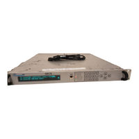
Advantech AMT-70 Installation And Operation Manual (160 pages)
AMT-70 Series. L-Band Satellite Modem 32k - 40 MSymbol BPSK, QPSK, OQPSK, 8PSK, 16QAM
Brand:
Advantech
| Category:
Modem
| Size: 3.69 MB
Table of Contents
Table of Contents
6
List of Figures
10
Safety Notice
13
Chapter 1 INTRODUCTION
29
The AMT-7X Family
29
1: the Amt-7
29
Product Overview
30
Description
30
AMT-73L Description
31
Ordering the Products Options
32
Figure 2: Amt-70 Family : P
33
Chapter 2 INSTALLATION
37
Introduction
37
Unpacking and Inspection
37
Unpacking
37
Inventory
37
Site Considerations
37
Installing the Unit
37
Power Requirements
38
AC Power & Fuse
38
Modem Rack/Shelf Support
38
DC Power & Fuse
38
Data Connections (AMT-70 Series)
39
Figure 3: Rack Mount Support Kit
39
Data Port RS-530
40
Data Port HSSI
40
Data Port Ethernet
40
Monitor and Control RS-232
40
Monitor and Control RS-485
40
Monitor and Control 10/100Baset Ethernet
40
Monitor and Control Alarms
40
Data Connections (AMT-73L Series)
40
Redundancy
40
Data Port EIA/TIA-449/MIL-STD-188-114
40
RF/IF Interfaces
41
External Clock Reference (MIL-STD-188-115)
41
Modulator L-Band Output (AMT-70L)
41
Modulator L Band Output (AMT-73L)
41
Demodulator L Band Input (AMT-70L and 75)
41
Figure 4: Buc Control Commands
41
Demodulator L-Band Input (AMT-73L)
42
Bringing the Modulator Online
42
Demodulator 70/140 Mhz if Input (AMT-70 and AMT-75)
42
Chapter 3 OPERATIONAL FEATURES
43
M&C Interface Descriptions
43
Acquisition, FEC, Modulation, and Eb/No
44
Demodulator Acquisition Tips
44
Choice of FEC
45
Link Budget Analysis and Eb/No (Viterbi and Viterbi R/S)
46
Figure 5: Fec / Mode / Rate C
46
Modem Applications and Typical Operating Scenarios
47
DVB (MPEG-2) Modulator
47
Figure 6: Allocated Bandwidth and Figure 7: Functional Blockd
47
Data Broadcast Modulator
48
SCPC Modem
48
Bandwidth-On-Demand Modem
48
Default, Memory Store and Recall Modes
48
Broadcast Mode
48
The Default Configuration
49
Programmable Memory Configurations
50
Clock Options and Buffers - Standard Interface Card
51
Transmit Timing
53
Internal Clock (SCT)
53
External (Terrestrial) Clock (SCTE)
53
Loop Timing (SCR)
53
RS530TFD Clock Recovery
53
Receive Timing
53
Doppler Buffer Auto
53
Doppler Buffer Enabled - Internal ST Clocking (SCT)
53
Doppler Buffer Enabled - External TT Clocking (SCTE)
54
Loop-Back, Pure Carrier, and BER Test Functions
54
Data Interface Near End/Far End Loop-Back
54
Data System Near End/Far End Loop-Back
55
IF Loop-Back
55
Pure Carrier Mode
55
Internal BER Test Pattern Generator and Tester
55
ASI Interfaces
56
BER Measurement
56
Chapter 4 ACTIVE FRONT PANEL
57
Quick Start Guide
57
Bench Test Setup
57
Figure 8: Amt-70L or Amt-73L L
57
Figure 9: Parameter Changes in
58
Placing Modem Online
59
Figure 10: Modem Commandsq
59
The Front Panel
60
Panel Indicators
60
Figure 11: the Amt-70 Front
61
Figure 12: the Amt-73L Active
61
Keypad & Display
62
Figure 13: the Amt-73L Front
62
Welcome Menu
63
Main Menu
63
Menu Tree Structure
63
Figure 14: Keypad Buttons and Their
63
TX Menu
65
The Transmit Menu
65
Available Settings and Parameters
66
Figure 15: Front Panel Display
66
RX Menu
67
The Available Settings and Parameters
67
Figure 16: Front Panel Display
68
INTERFACE Menu
69
Figure 17: Front Panel Display
70
MONITOR Menu
71
FUNCTION Menu
75
The INFORMATION Submenu
75
The CONFIGURATION Submenu
75
The CONTROL Submenu
76
The CONTROL/PORTS/NETWORK Option
76
The CONTROL/PORTS/RS485 Option
77
The CONTROL/BUC Submenu
78
The CONTROL/LNB Submenu
78
The CONTROL/LCD Submenu
78
The TESTS Submenu
79
The REBOOT Option
79
Executing Variable Commands from the Front Panel
80
Figure 20: Acceptablep
80
Chapter 5 MANAGING the MODEM
81
Using the RS-232 Port
81
Using RS-485 Rear Panel Remote M&C
81
Using the Ethernet Port
82
Starting the Modem
82
Login to the Modem
83
Figure 21: Booting the Modem
83
Figure 22: Login to the Modem in
83
Setting the Security
84
Setting the Modem Date and Time
84
Figure 23: Changing the Security
84
Using the Modem Shell
85
Command Format
85
Command Help
85
Commands Recall and Editing
85
Figure 24: Listing the Modem Command Set
85
Figure 25: Modem Shell Function Keys
85
Commands Completion Mode
86
Command Completion Mode
86
Figure 26: Using the Command Completion Mode
86
Figure 27: Using the Command Completion Mode
86
Configuring the RS-485 Port
87
Scheduling Periodic Commands
87
Figure 28: Scheduling Monotonic Commands
87
Accessing the Modem through a Network
88
Configuring the Network Address
88
Figure 30: Configuring the Tx
88
Figure 31: Configuring the Rx
88
Configuring the Routing Tables
89
Using Telnet for Remote Control
89
Figure 33: Login Using Telnet
89
Using FTP for Software Download
90
Figure 34: Downloadings
90
Downloading from the RS-232 Serial Port
91
Using SNMP
92
Introduction
92
How to Configure SNMP
92
The SNMP MIB Source File
93
Modem Events and Logging
93
The SNMP Traps
94
Using the Log File
94
Chapter 6 THE MODEM COMMAND SET
96
Introduction
96
The Command Syntax
96
The Modulator/Demodulator Standard Commands
96
Figure 37: Amt70 Command Syntax
96
Figure 38: Amt-70 Standard
96
The Modulator Specific Commands
98
Figure 39: Monitor Specificsc
98
The Demodulator Specific Commands
99
Figure 40: Demodulator Specific
99
Getting the Chassis Configuration and Status
100
The Monitor and Control Commands
100
Figure 41: Monitor Commands
100
The Interface Commands
102
ASI Interface Commands
102
RS530 + 1*HSSI Interface
102
HSSI Interface
103
Figure 43: 3*Hssi Commandss
103
Chapter 7 Using the Rs-485 Port
104
The RS-485 Control Commands
104
The Command Mode
104
The Packet Protocol
105
Chapter 8 CABLES and PIN-OUTS
106
Rear Panel Connector Arrangements
106
Figure 44: Back Panelc
106
RS-442/449 to RS-530 Adapter Cable
107
Figure 45
107
Figure 46
107
RS-422/449 to RS-530 Y-Cable
108
Data Interface Pin-Outs (AMT-70)
109
Figure 47: Rs-530 Data Interface
109
HSSI Connector Pin-Outs
110
Ethernet M&C Connector Pin-Outs
110
Ethernet IP Router Connector Pin-Outs (AMT-73L)
111
Connector Pin-Outs
111
Null Modem Cable Assembly
111
Connector Pin-Outs
112
EIA/TIA-449 AMT-73L Connector Pin-Outs
112
RS232 Pin-Out (AMT-73L)
113
Sspb/Modem Cabling Requirements
113
Alarms Connector Description
114
L-Band Transmit Cable
114
L-Band Receive Cable
114
DB15 - DB15 - Switch Cable
115
Chapter 9 Turbo Code Details
116
Turbo Product Code Overview
116
AMT7X Family TPC Overview
117
Crcs and Scrambling
117
Calculating the Code Rate
118
Framing
118
Chapter 10 BUC and ADVANTECH SSPB
120
SSPB (BUC) Interface Connections
120
LNB Interface Connections
120
M&C Interface Connections
120
Modem Configuration
120
TX Carrier Enable
121
Chapter 11 REDUNDANCY
122
Hardware Installation
122
ASI Interface
122
HSSI Interface
124
Front Panel Push Buttons
127
LED Indicators
127
Software Configuration
128
Messages
131
Chapter 12 APPENDIX A SYSTEM CONSIDERATIONS
132
Typical AMT-70L/AMT-73L Interconnections
132
Setting the Transmit Levels
133
LNB, BUC & Antenna Installation
134
Choosing the LNB & BUC
134
LNB Physical Installation
134
Antenna Alignment
134
Satellite Position
134
Antenna Pointing Angles
135
Pointing the Antenna
137
Input Level Range Versus Symbol Rate
138
Chapter 13 APPENDIX B S/N to Eb/No CONVERSION
140
Chapter 14 APPENDIX C EMBEDDED ROUTER
144
Chapter 15 APPENDIX D Turbo Product Code Performance
147
Chapter 16 APPENDIX E DVB-S2 Theoretical Performance
160
Advertisement
Advertisement
Related Products
Advantech AMT-73
Advantech AMT-75
Advantech AMAX-5015
Advantech AMAX-3110-06AE
Advantech AMAX-354
Advantech AMAX-5060
Advantech AMAX-1754
Advantech AMAX-1752
Advantech AMAX-175 Series
Advantech AMAX-5017C
Advantech Categories
Motherboard
Computer Hardware
Desktop
Touch Panel
Network Router
More Advantech Manuals
Login
Sign In
OR
Sign in with Facebook
Sign in with Google
Upload manual
Upload from disk
Upload from URL