Sign In
Upload
Manuals
Brands
Advantech Manuals
Motherboard
AIMB-781QG2
Advantech AIMB-781QG2 Manuals
Manuals and User Guides for Advantech AIMB-781QG2. We have
1
Advantech AIMB-781QG2 manual available for free PDF download: User Manual
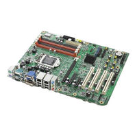
Advantech AIMB-781QG2 User Manual (100 pages)
LGA1155 Intel Core i7/i5/i3/ Pentium ATX with DVI/VGA, Dual Gigabit LAN, DDR3, SATA III
Brand:
Advantech
| Category:
Motherboard
| Size: 4.63 MB
Table of Contents
Declaration of Conformity
4
Table of Contents
7
Chapter 1 Hardware Configuration
11
Introduction
12
Features
12
Specifications
13
System
13
Memory
13
Input/Output
13
Graphics
13
Ethernet LAN
14
Industrial Features
14
Mechanical and Environmental Specifications
14
Jumpers and Connectors
15
Table 1.1: Jumper List
15
Table 1.2: Connectors
15
Board Layout: Jumper and Connector Locations
17
Figure 1.1 Jumper and Connector Locations
17
Figure 1.2 I/O Connectors
17
AIMB-781 Block Diagram
18
Figure 1.3 AIMB-781 Block Diagram
18
Safety Precautions
18
Jumper Settings
19
How to Set Jumpers
19
CMOS Clear (JCMOS1)
19
Table 1.3: JCMOS1
19
Watchdog Timer Output (JWDT1)
20
Table 1.4: Watchdog Timer Output (JWDT1)
20
Table 1.5: ATX/AT Mode Selector (PSON1)
20
Table 1.6: COM3 RS-232/422/485 Mode Selector (JSETCOM3
20
System Memory
21
Memory Installation Procedures
21
Cache Memory
21
Processor Installation
21
PCI Bus Routing Table
21
Chapter 2 Connecting Peripherals
23
Introduction
24
Parallel Port (LPT1)
24
USB Ports (LAN1_USB12, LAN2_USB3/4, USB5/6, USB7/8, USB9/10, USB11/12 & USB13/14)
25
USB Power Switch
26
VGA Connector and DVI-D Connector (VGA1+DVI1)
27
Serial Ports (COM1, COM2, COM3, COM4, COM5 & COM6)
28
PS/2 Keyboard and Mouse Connector (KBMS1)
29
External Keyboard & Mouse (KBMS2)
30
CPU Fan Connector (CPUFAN1)
30
System FAN Connector (SYSFAN1 and SYSFAN2)
31
Front Panel Connectors (JFP1, JFP2 & JFP3)
31
Power LED and Keyboard Lock (JFP3)
32
Table 2.1: PS/2 or ATX Power Supply LED Status
32
External Speaker (JFP2 Pins 1, 4, 7 & 10)
32
HDD LED Connector (JFP2 Pins 2 & 5)
32
SNMP Sm_Bus Connector (JFP2 Pins 8 & 11)
32
ATX Soft Power Switch (JFP1 Pins 3 & 6)
32
Reset Connector (JFP1 Pins 9 & 12)
32
Line Out, MIC in Connector (AUDIO1)
33
Pin Alarm Board Connector (VOLT1)
33
Case Open Connector (JCASE1)
34
Front Panel LAN Indicator Connector (LAN_LED1)
35
Table 2.2: Front Panel LAN Indicator Connector
35
PCI Slots (PCI 1 ~ PCI 4)
37
Pcie X16 Expansion Slot (PCIEX16_1)
37
Pciex4_1
38
Pciex1_1
38
Auxiliary 4-Pin Power Connector (ATX12V1)
39
SPI Flash Connector(SPI_CN1)
39
Low Pin Count Connector (LPC1)
40
Table 2.3: Advantech LPC Module List
40
Chapter 3 BIOS Operation
41
Figure 3.1 Main Setup Screen
42
Introduction
42
Entering BIOS Setup
42
Main Menu
43
Figure 3.2 Main Setup Screen
43
System Time / System Date
43
Advanced BIOS Features Setup
44
Figure 3.3 Advanced BIOS Features Setup Screen
44
ACPI Settings
45
Figure 3.4 ACPI Settings
45
Trusted Computing
46
Figure 3.5 TPM Settings
46
CPU Configuration
47
Figure 3.6 CPU Configuration
47
Figure 3.7 CPU Information
47
SATA Configuration
49
Figure 3.8 SATA Configuration
49
Intel IGD SWSCI Opregion Configuration
50
Figure 3.9 Intel IGD SWSCI Opregion Configuration
50
Intel TXT(LT) Configuration
51
Figure 3.10Intel Trusted Execution Technology Configuration
51
USB Configuration
52
Figure 3.11USB Configuration
52
NCT6776 Super IO Configuration
53
Figure 3.12Super IO Configuration
53
Figure 3.13Serial Port 1 Configuration
53
Figure 3.14Serial Port 2 Configuration
54
Figure 3.15Parallel Configuration
54
H/W Monitor
55
Figure 3.16PC Health Status
55
F81216 Super IO Configuration
56
Figure 3.17F81216 Super IO Configuration
56
Figure 3.18Serial Port 3 Configuration
57
Figure 3.19Serial Port 4 Configuration
58
Figure 3.20Serial Port 5 Configuration
58
Figure 3.21Serial Port 6 Configuration
59
AMT Configuration
60
Figure 3.22Amtconfiguration
60
Serial Port Console Redirection
61
Figure 3.23Serial Port Console Redirection
61
Chipset
63
Figure 3.24Chipset
63
North Bridge
64
Figure 3.25North Bridge
64
South Bridge
65
Figure 3.26South Bridge
65
Figure 3.27USB Configuration
66
ME Subsystem
67
Figure 3.28ME Subsystem
67
Boot
68
Figure 3.29Boot
68
Security
69
Figure 3.30Security
69
Save & Exit
70
Figure 3.31Save & Exit
70
Chapter 4 Chipset Software Installation Utility 61
72
Before You Begin
72
Introduction
72
Windows XP / Windows 7 Driver Setup
73
Chapter 5 VGA Setup
75
Windows Xp/Windows 7 Driver Setup
76
Introduction
76
Chapter 6 LAN Configuration
77
Features
78
Introduction
78
Installation
78
Win XP /Win 7 Driver Setup (LAN)
78
A.1 Watchdog Timer Overview
80
A.2 Programming the Watchdog Timer
80
Appendix A Programming the Watchdog Timer
82
Table A.1: Watchdog Timer Registers
82
A.2.1 Example Programs
82
B.1 Parallel Port (LPT1)
88
Appendix B I/O Pin Assignments
88
Table B.1: Parallel Port (LPT1)
88
B.2 USB Header (USB56, USB78, USB910, USB1112 & USB1314)
88
Table B.2: USB Header
88
Table B.3: VGA Connector (VGA1)
89
B.4 RS-232 Interface (COM3~6)
89
Table B.4: RS-232 Interface (COM1)
89
B.5 PS/2 Keyboard and Mouse Connector (KBMS1)
90
Table B.5: Keyboard and Mouse Connector (KBMS1)
90
B.6 External Keyboard Connector (KBMS2)
90
Table B.6: External Keyboard Connector (KBMS2)
90
B.7 Infrared (IR) Connector (JIR1)
91
Table B.7: Infrared Connector (JIR1)
91
B.8 System Fan Power Connector (SYSFAN1/SYSFAN2)
91
Table B.8: Fan Power Connector (SYSFAN1/SYSFAN2)
91
B.9 Power LED and Keyboard Lock (JFP3)
91
Table B.9: Power LED and Keyboard Lock (JFP3)
91
B.10 External Speaker Connector (JFP2)
92
Table B.10:External Speaker Connector (JFP2)
92
B.11 Reset Connector (JFP1)
92
Table B.11:Reset Connector (JFP1)
92
B.12 HDD LED Connector (JFP2)
92
Table B.12:HDD LED Connector (JFP2)
92
B.13 ATX Soft Power Switch (JFP1)
92
Table B.13:ATX Soft Power Switch (JFP1)
93
B.14 H/W Monitor Alarm (JOBS1)
93
B.15 SNMP SM_BUS Bus Connector (JFP2)
93
Table B.15:SM Bus Connector (JFP2)
93
B.16 USB/LAN Ports (LAN1_USB12 and LAN2_USB34)
94
Table B.16:USB Port
94
Table B.17:Giga LAN 10/100/1000 Base-T RJ-45 Port
94
B.17 Line Out, MIC in Connector (AUDIO1)
94
B.18 Front Panel Audio Connector (FPAUD1)
95
Table B.18:Front Panel Audio Connector (FPAUD1)
95
B.19 8-Pin Alarm Board Connector (VOLT1)
95
Table B.19:8-Pin Alarm Board Connector (VOLT1)
95
B.20 Case Open Connector (JCASE1)
96
Table B.20:Case Open Connector (JCASE1)
96
B.21 Front Panel LAN LED Connector (LAN_LED1)
96
Table B.21:LAN LED Connector (LANLED1)
96
B.22 SPI_CN1: SPI Flash Card Pin Connector
96
Table B.22:SPI_CN1:SPI Fresh Card Pin Connector
96
B.23 System I/O Ports
97
Table B.23:System I/O Ports
97
B.24 DMA Channel Assignments
97
Table B.24:DMA Channel Assignments
97
B.25 Interrupt Assignments
98
Table B.25:Interrupt Assignments
98
B.26 1St MB Memory Map
98
Table B.26:1St MB Memory Map
98
Advertisement
Advertisement
Related Products
Advantech AIMB-781
Advantech AIMB-780
Advantech AIMB-785
Advantech AIMB-782
Advantech AIMB-781QVG
Advantech AIMB-784
Advantech AIMB-786
Advantech AIMB-787
Advantech AIMB-788
Advantech AIMB-744 Series
Advantech Categories
Motherboard
Computer Hardware
Desktop
Touch Panel
PCI Card
More Advantech Manuals
Login
Sign In
OR
Sign in with Facebook
Sign in with Google
Upload manual
Upload from disk
Upload from URL