User Manuals: Advantech AIMB-786 Industrial Motherboard
Manuals and User Guides for Advantech AIMB-786 Industrial Motherboard. We have 2 Advantech AIMB-786 Industrial Motherboard manuals available for free PDF download: User Manual, Startup Manual

Advantech AIMB-786 User Manual (116 pages)
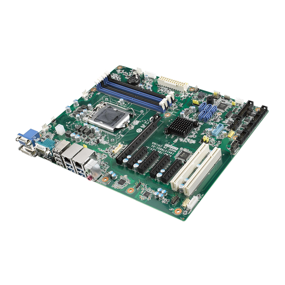
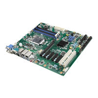
LGA1151 Intel Core i7/i5/i3 ATX with Triple Display, Dual GbE LAN, SATA 3.0, USB 3.1, DDR4
Brand: Advantech
|
Category: Motherboard
|
Size: 1 MB
Table of Contents
Advertisement
Advantech AIMB-786 Startup Manual (4 pages)
LGA1151 Intel Core i7/i5/i3 ATX with Triple Display, Dual GbE LAN, SATA 3.0, USB 3.1, DDR4
Brand: Advantech
|
Category: Computer Hardware
|
Size: 1 MB