Sign In
Upload
Manuals
Brands
ADLINK Technology Manuals
Controller
ROScube-X RQX-58G/580
ADLINK Technology ROScube-X RQX-58G/580 Manuals
Manuals and User Guides for ADLINK Technology ROScube-X RQX-58G/580. We have
1
ADLINK Technology ROScube-X RQX-58G/580 manual available for free PDF download: User Manual
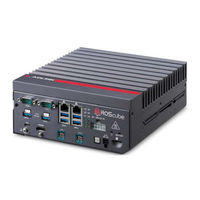
ADLINK Technology ROScube-X RQX-58G/580 User Manual (55 pages)
Brand:
ADLINK Technology
| Category:
Controller
| Size: 2.05 MB
Table of Contents
Preface
3
Table of Contents
5
List of Tables
7
List of Figures
9
Introduction
11
Overview
11
Features
11
Packing List
12
Optional Accessories
12
Specifications
13
Rqx-58G(-E), Rqx-580(-E)
13
Table 2-1: RQX-58G/58G-E, RQX-580/580-E Specifications
13
RQX-58X Series Functional Block Diagram
16
Figure 2-1: RQX-58X Series Functional Block Diagram
16
Display Options
17
Table 2-2: Maximum Display Resolution
17
Mechanical Dimensions
18
Figure 2-2: RQX-58X Series Top View
18
Figure 2-3: RQX-58X Series "E" Top View
19
Figure 2-4: RQX-580 Front and Rear View
20
Figure 2-5: RQX-58G Front and Rear View
21
Figure 2-6: RQX-580-E Front and Rear View
22
Figure 2-7: RQX-58G-E Front and Rear View
23
Figure 2-8: RQX-58X Series Side View
24
Figure 2-9: RQX-58X Series Bottom View
25
System Layout
27
Front Panel
27
Table 3-1: Front Panel I/O Legend
27
Figure 3-1: Front Panel I/O
27
Table 3-2: Side Panel I/O Legend
28
Figure 3-2: Front Panel I/O
28
Table 3-3: Multi-I/O DB-50 Connector Pin Definition
30
Table 3-4: HDMI Connector Pin Definition
31
Table 3-5: Ethernet Port Pin Definition
32
Figure 3-3: Ethernet Port and Leds
32
Table 3-6: Active/Link LED Indicators
33
Table 3-7: Speed LED Indicators
33
Table 3-8: DC Power Input Pin Definition
33
Figure 3-4: DC Power Input
33
Table 3-9: COM Port D-Sub 9-Pin RS-232/485 Pin Definitions
35
Figure 3-5: COM Port D-Sub 9-Pin
35
Table 3-10: Microsd Card Slot Pin Definition
36
Table 3-11: USB 2.0 OTG Micro-A/B Pin Definition
36
Figure 3-6: Microsd Card Slot
36
Figure 3-7: USB 2.0 OTG Micro-A/B Port
36
Table 3-12: Mini FAKRA Connector Pin Definition
37
Figure 3-8: Mini FAKRA Connector
37
Internal I/O Connectors
38
Figure 3-9: RQX-58X Board Layout
38
Table 3-13: RQX-58X Mainboard Connector Legend
39
Figure 3-10: RQX-58X Mainboard Connectors
39
Table 3-14: Function Module Connector Legend
40
Figure 3-11: Function Module Connectors
40
Table 3-15: USB 2.0 OTG Micro-A/B Pin Definition
41
Figure 3-12: SW Debug Port
41
Getting Started
43
Attach DC Power Connector
43
Mounting the RQX-58X Series
44
A Appendix: Power
47
Power Consumption Reference
47
Table A-1: Power Consumption
47
Important Safety Instructions
49
Advertisement
Advertisement
Related Products
ADLINK Technology ROScube-X RQX-58 Series
ADLINK Technology ROScube-X RQX-58G-E/580-E
ADLINK Technology ROScube-Pico TGL RQP-T37
ADLINK Technology ROScube-Pico TGL RQP-T35
ADLINK Technology ROScube-Pico TGL RQP-T33
ADLINK Technology RQI-58
ADLINK Technology RQI-57
ADLINK Technology RQI-57-E
ADLINK Technology RQI-55-E
ADLINK Technology RQI-58-E
ADLINK Technology Categories
Computer Hardware
Motherboard
PCI Card
Control Unit
Controller
More ADLINK Technology Manuals
Login
Sign In
OR
Sign in with Facebook
Sign in with Google
Upload manual
Upload from disk
Upload from URL