Sign In
Upload
Manuals
Brands
ABB Manuals
DC Drives
ACS880-307LC
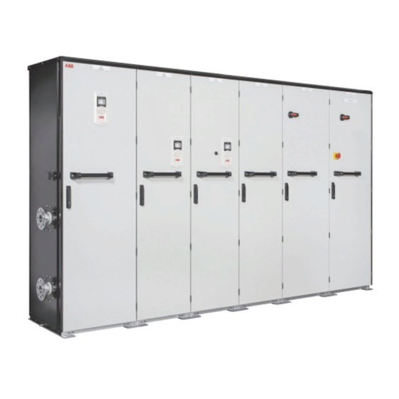
ABB ACS880-307LC Diode Supply Units Manuals
Manuals and User Guides for ABB ACS880-307LC Diode Supply Units. We have
2
ABB ACS880-307LC Diode Supply Units manuals available for free PDF download: Hardware Manual
ABB ACS880-307LC Hardware Manual (138 pages)
diode supply units
Brand:
ABB
| Category:
Industrial Equipment
| Size: 17 MB
Table of Contents
Table of Contents
5
Introduction to the Manual
11
Contents of this Chapter
11
Applicability
11
Safety Instructions
11
Target Audience
11
Categorization by Frame Size and Option Code
12
Use of Component Designations
12
Terms and Abbreviations
12
Related Documents
13
Operation Principle and Hardware Description
15
Contents of this Chapter
15
Operation Principle
15
Overview Diagram of the Rectifier Bridge
16
6- and 12-Pulse Supply Connections
16
Overview Diagram of the Drive System
17
Layout Drawings
19
Overview Layout Drawing of the Supply Unit
19
Auxiliary Control Cubicle Layout
20
Incoming Cubicle Layout - Bottom Cable Entry
21
Ka Input Cubicle (Option +F274)
22
Supply Module Cubicle Layout - Frame 1×D8T
23
Supply Module Cubicle Layout - Frame 1×D8T, Electrical Components
23
Supply Module Cubicle Layout - Frame 1×D8T, Cooling Circuit
24
Supply Module Cubicle Layout - Frame 2×D8T
24
Supply Module Cubicle Layout - Frame 2×D8T, Electrical Components
24
Supply Module Cubicle Layout - Frame 2×D8T, Cooling Circuit
25
Supply Module Layout - Frame D8T
26
Overview of the Control Connections of the UCU Control Unit
27
Overview of the Control Connections of the BCU Control Unit
28
Supply Unit Control Devices
29
Overview of Door Switches and Lights
29
Main Disconnecting Device [Q1]
29
Auxiliary Voltage Switch [Q21]
30
Grounding Switch [Q9]
30
Operating Switch [S21]
30
Emergency Stop Button [S61] and Reset Button [S62]
30
Control Panel [A59]
31
PC Connection
31
Fieldbus Control
31
Type Designation Labels
32
Type Designation Keys
34
Type Designation Key of the Supply Unit
34
Basic Code
34
Option Codes
34
Type Designation Key of the Diode Supply Module
37
Miscellaneous
37
Roxtec Cable Entry (Option +H394)
37
Electrical Installation
39
Contents of this Chapter
39
Electrical Safety Precautions
40
General Notes
41
Static Electricity
41
Handling Fiber Optic Cables
42
Measuring the Insulation
42
Measuring the Insulation Resistance of the Drive
42
Measuring the Insulation Resistance of the Input Power Cable
42
Connecting the Input Power Cables - Cable Entry in Standard Incoming Cubicle
42
Connection Diagram - 6-Pulse Supply Unit
42
Connection Diagram - 12-Pulse Supply Unit (Option +A004)
43
Connection Procedure - Bottom Cable Entry (Option +G350)
43
Removing Shrouds in Front of the Input Cable Terminals
43
Connecting the Cables
44
Replacing Shrouds and Beams in Front of Input Power Cable Terminals
45
Connecting Input Power Cables - Cable Entry in 100 Ka Input Cubicle (Option +F274)
46
Connection Diagram
46
Connection Procedure
46
Removing Shrouds and Beams in Front of the Input Cable Terminals
46
Connecting the Cables
47
Replacing Shrouds and Beams in Front of Input Power Cable Terminals
49
Use of Fasteners in Cable Lug Connections
51
Connecting the External Power Supply Cable for the Auxiliary Circuit (Option +G307)
51
Wiring the Functional Safety Options
51
Connecting the Control Cables
52
General Instructions on Connecting the Control Cables to the Drive
52
Control Cable Connection Procedure
52
Connecting a PC
56
Control Unit (UCU)
57
Contents of this Chapter
57
General
57
Layout
57
Default I/O Diagram of the Supply Control Unit
61
Additional Information on the Connections
63
Power Supply for the Control Unit (XPOW)
63
Digital Interlock (DIIL)
63
Control Panel Connection (XPAN)
64
Safe Torque off (XSTO, XSTO OUT)
64
Microsdhc Memory Card Slot
64
Connector Data
65
Ground Isolation Diagram
67
Control Unit (BCU)
69
Contents of this Chapter
69
General
69
Layout
70
Default I/O Diagram of the Supply Control Unit
72
Additional Information on the Connections
74
Power Supply for the Control Unit (XPOW)
74
Digital Interlock (DIIL)
74
FSO Safety Functions Module Connection (X12)
74
SDHC Memory Card Slot
74
Connector Data
75
BCU Ground Isolation Diagram
77
Installation Checklist
79
Contents of this Chapter
79
Checklist
79
Start-Up
81
Contents of this Chapter
81
Start-Up Procedure
81
Safety
81
Checks/Settings with no Voltage Connected
82
Starting and Checking the Cooling System
82
Powering up the Auxiliary Circuit of the Drive
82
Setting up the Supply Unit Parameters
83
Powering up the Main Circuit of the Drive
83
Validating the Safety Functions
84
On-Load Checks
84
Switching the Supply Unit off
84
Disconnecting and Temporary Grounding the Drive
84
Maintenance
85
Contents of this Chapter
85
Maintenance Intervals
85
Description of Symbols
85
Recommended Maintenance Intervals after Start-Up
86
Maintenance Timers and Counters
87
Internal Liquid-Cooling System
87
Cabinet
87
Cleaning the Interior of the Cabinet
87
Cleaning the Exterior of the Drive
88
Fans
88
Replacing the Fan in the 600 MM Wide Incoming Cubicle
88
Replacing the Cooling Fan of a D8T Supply Module
89
Replacing the Cooling Fan in the 100 Ka Input Cubicle
90
Fuses
92
Replacing the AC Fuses - Supply Module Cubicle
92
Replacing AC Fuses - 100 Ka Input Cubicle (Option +F274)
94
Replacing the DC Fuses
95
Supply Module
97
Replacing the D8T Supply Module
97
Control Panel
101
UCU Control Unit
102
UCU Control Unit Types
102
Replacing the Memory Unit of the UCU Control Unit
102
Replacing the UCU Control Unit Battery
103
Replacing the Microsd/Microsdhc Memory Card of UCU Control Unit
103
BCU Control Unit
104
BCU Control Unit Types
104
Replacing the Memory Unit (BCU)
104
Replacing the BCU Control Unit Battery
105
Leds and Other Status Indicators
105
Control Panel and Panel Platform/Holder Leds
106
Control Unit Leds (BCU-X2)
106
Control Unit Leds (UCU-22
107
Functional Safety Components
107
Internal Cooling Circuit
109
Contents of this Chapter
109
Applicability
109
Internal Cooling System
109
Connection to a Cooling Unit
111
Connection to an ACS880-1007LC Cooling Unit
111
Connection to a Custom Cooling Unit
111
General Requirements
111
Coolant Temperature Control
111
Filling up and Bleeding the Internal Cooling Circuit
112
Drive Line-Ups with an ACS880-1007LC Cooling Unit
112
Drive Line-Ups with a Custom Cooling Unit
112
Draining the Internal Cooling Circuit
113
Maintenance Intervals
113
Technical Data for the Internal Cooling Circuit
114
Coolant Specification
114
Coolant Type
114
Temperature Limits
114
Pressure Limits
116
Coolant Flow Rate Limits
116
Cooling Circuit Materials
116
Technical Data
117
Contents of this Chapter
117
Ratings
117
Derating
118
Surrounding Air Temperature Derating
118
Coolant Temperature Derating
119
Antifreeze Content Derating
119
Altitude Derating
119
Type Equivalence Table
119
Fuses
120
Main Circuit AC Fuses - Standard Incoming Cubicle
120
Main Circuit AC Fuses - 100 Ka Input Unit (+F274)
121
Main Circuit DC Fuses
121
Dimensions and Weights
122
Free Space Requirements
123
Cooling Data and Noise
124
Terminal and Cable Entry Data for the Input Power Cable
125
400 MM Wide Input Cubicle
126
600 MM Wide Incoming Cubicle or Input Cubicle
127
Ka Input Cubicle (Option +F274)
128
Tightening Torques
128
Electrical Connections
128
Mechanical Connections
129
Insulation Supports
129
Cable Lugs
129
Typical Power Cable Sizes
129
Electrical Power Network Specification
130
Control Unit (Board) Connection Data
131
Auxiliary Circuit Current Consumption
131
Efficiency
131
Energy Efficiency (Ecodesign)
131
Protection Classes
132
Ambient Conditions
132
Colors
133
Materials
133
Drive
133
Packaging of Drive
133
Packaging of Options
133
Manuals
134
Disposal
134
Applicable Standards
134
Markings
134
Disclaimers
134
Generic Disclaimer
134
Cyber Security Disclaimer
134
Further Information
137
Advertisement
ABB ACS880-307LC Hardware Manual (106 pages)
Diode supply units
Brand:
ABB
| Category:
DC Drives
| Size: 13 MB
Table of Contents
Table of Contents
5
Introduction to the Manual
9
Contents of this Chapter
9
Applicability
9
Safety Instructions
9
Target Audience
9
Categorization by Frame Size and Option Code
10
Use of Component Designations
10
Terms and Abbreviations
10
Related Documents
11
Operation Principle and Hardware Description
13
Contents of this Chapter
13
Operation Principle
13
Overview Diagram of the Rectifier Bridge
14
6- and 12-Pulse Supply Connections
14
Overview Diagram of the Drive System
16
Layout Drawings
17
Overview Layout Drawing of the Supply Unit
17
Auxiliary Control Cubicle Layout
18
Incoming Cubicle Layout - Bottom Cable Entry
19
Supply Module Cubicle Layout - Frame 1×D8T
20
Supply Module Cubicle Layout - Frame 1×D8T, Electrical Components
20
Supply Module Cubicle Layout - Frame 1×D8T, Cooling Circuit
20
Supply Module Cubicle Layout - Frame 2×D8T
21
Supply Module Cubicle Layout - Frame 2×D8T, Electrical Components
21
Supply Module Cubicle Layout - Frame 2×D8T, Cooling Circuit
22
Supply Module Layout - Frame D8T
23
Overview of the Control Connections of the BCU Control Unit
24
Supply Unit Control Devices
25
Overview of Door Switches and Lights
25
Main Disconnecting Device [Q1.X]
25
Auxiliary Voltage Switch [Q21]
26
Grounding Switch [Q9.X]
26
Operating Switch [S21]
26
Emergency Stop Button [S61]
27
E-Stop Reset Button [S62] and Indication Lamp [P62]
27
Other Optional Door Controls
27
Control Panel
27
PC Connection
27
Fieldbus Control
28
Type Designation Labels
28
Type Designation Keys
30
Type Designation Key of the Supply Unit
30
Basic Code
30
Option Codes
30
Type Designation Key of the Diode Supply Module
32
Electrical Installation
35
Contents of this Chapter
35
Electrical Safety Precautions
36
General Notes
37
Static Electricity
37
Optical Components
37
Measuring the Insulation
38
Measuring the Insulation of the Drive
38
Measuring the Insulation of the Input Power Cable
38
Connecting the Input Power Cables
38
Connection Diagram - 6-Pulse Supply Unit
38
Connection Diagram - 12-Pulse Supply Unit (Option +A004)
38
Connection Procedure - Bottom Cable Entry
39
Connecting the External Power Supply Cable for the Auxiliary Circuit (Option +G307)
42
Wiring the Functional Safety Options
42
Connecting the Control Cables
42
Control Cable Connection Procedure
42
Grounding the Outer Shields of the Control Cables at the Cabinet Entry
42
Routing the Control Cables Inside the Cabinet
44
Connecting Control Cabling
44
Connecting a PC
46
The Control Unit
47
Contents of this Chapter
47
BCU-X2 Layout
48
Default I/O Diagram of the Supply Control Unit
50
External Power Supply for the Control Unit (XPOW)
52
The X485 Connector
52
Safe Torque off (XSTO, XSTO OUT)
53
FSO-XX Safety Functions Module Connection (X12)
53
SDHC Memory Card Slot
53
Connector Data
54
BCU-X2 Ground Isolation Diagram
56
Installation Checklist
57
Contents of this Chapter
57
Checklist
57
Start-Up
59
Contents of this Chapter
59
Start-Up Procedure
60
Basic Checks with no Voltage Connected
60
Starting and Checking the Cooling System
60
Connecting Voltage to Input Terminals and Auxiliary
60
Setting the Supply Unit Parameters
61
Powering up the Drive
61
Safety Function Validation
62
On-Load Checks
62
Switching the Supply Unit off
62
Disconnecting and Temporary Grounding the Drive
62
Maintenance
63
Contents of this Chapter
63
Maintenance Intervals
63
Maintenance Timers and Counters
65
Internal Liquid-Cooling System
65
Power Connections
65
Retightening the Power Connections
65
Fans
65
Replacing the Fan in the 600 MM Wide Incoming Cubicle
65
Replacing the Cooling Fan of a D8T Supply Module
67
Fuses
68
Checking and Replacing the AC Fuses
68
Checking and Replacing the DC Fuses
69
Supply Module
70
Replacing the D8T Supply Module
70
Control Panel
74
Cleaning the Control Panel
74
Replacing the Control Panel Battery
74
Control Unit
75
Replacing the Memory Unit
75
Replacing the BCU Control Unit Battery
75
Leds and Other Status Indicators
76
Control Panel and Panel Platform/Holder Leds
76
Control Unit Leds
77
Internal Cooling Circuit
79
Contents of this Chapter
79
Applicability
79
Internal Cooling System
79
Connection to a Cooling Unit
81
Connection to an ACS880-1007LC Cooling Unit
81
Connection to a Custom Cooling Unit
81
General Requirements
81
Coolant Temperature Control
81
Filling up and Bleeding the Internal Cooling Circuit
82
Drive Line-Ups with an ACS880-1007LC Cooling Unit
82
Drive Line-Ups with a Custom Cooling Unit
82
Draining the Internal Cooling Circuit
84
Maintenance Intervals
84
Technical Data
84
Coolant Specification
84
Coolant Type
84
Temperature Limits
84
Pressure Limits
86
Coolant Flow Rate Limits
86
Cooling Circuit Materials
86
Technical Data
89
Contents of this Chapter
89
Ratings
89
Derating
90
Surrounding Air Temperature Derating
90
Coolant Temperature Derating
91
Antifreeze Content Derating
91
Altitude Derating
91
Type Equivalence Table
91
Fuses
92
Main Circuit AC Fuses
92
Main Circuit DC Fuses
93
Dimensions, Weights and Free Space Requirements
94
Cooling Data and Noise
95
Terminal and Cable Entry Data for the Input Power Cable
95
400 MM Wide Input Cubicle
96
600 MM Wide Incoming Cubicle or Input Cubicle
97
Tightening Torques
98
Electrical Connections
98
Mechanical Connections
98
Insulation Supports
98
Cable Lugs
98
Typical Power Cable Sizes
99
Electrical Power Network Specification
101
Control Unit (Board) Connection Data
101
Auxiliary Circuit Current Consumption
101
Efficiency
101
Protection Classes
101
Ambient Conditions
102
Materials
103
Color
103
Package
103
Vertical Package
103
Disposal
103
Applicable Standards
103
Markings
104
Disclaimers
104
Generic Disclaimer
104
Cybersecurity Disclaimer
104
Advertisement
Related Products
ABB ACS880-31
ABB ACS880-34-293A-3
ABB ACS880-34-505A-3
ABB ACS880-34-585A-3
ABB ACS880-34-650A-7
ABB ACS880-34-240A-5
ABB ACS880-34-302A-5
ABB ACS880-34-414A-5
ABB ACS880-34-142A-7
ABB ACS880-34-174A-7
ABB Categories
Industrial Equipment
Controller
Measuring Instruments
Battery Charger
DC Drives
More ABB Manuals
Login
Sign In
OR
Sign in with Facebook
Sign in with Google
Upload manual
Upload from disk
Upload from URL