Sign In
Upload
Manuals
Brands
ABB Manuals
DC Drives
ACS550-U2
ABB ACS550-U2 Manuals
Manuals and User Guides for ABB ACS550-U2. We have
3
ABB ACS550-U2 manuals available for free PDF download: User Manual, Installation Supplement Manual
ABB ACS550-U2 User Manual (306 pages)
Brand:
ABB
| Category:
DC Drives
| Size: 9.04 MB
Table of Contents
ACS550-02/U2 Drive Manuals
2
Safety Information
4
Use of Warnings and Notes
4
Table of Contents
7
Table of Contents
10
Installation and Commissioning Flowchart
10
Planning the Electrical Installation
11
Checking the Compatibility of the Motor
11
Protecting the Motor Winding and Bearings
11
Requirements Table
12
Supply Connection
14
Disconnecting Device (Means)
14
Thermal Overload and Short-Circuit Protection
15
Ground Fault Protection
16
Emergency Stop Devices
17
Selecting the Power Cables
17
Conduit
18
Armored Cable / Shielded Power Cable
18
Power Factor Compensation Capacitors
19
Equipment Connected to the Motor Cable
20
Protecting the Relay Output Contacts and Attenuating Disturbances
21
Selecting the Control Cables
22
Connection of a Motor Temperature Sensor to the Drive I/O
23
Routing the Cables
23
Installation
25
Moving the Drive
25
Before Installation
27
Delivery Check
27
Drive Identification
27
Drive Labels
27
Type Code
28
Ratings and Frame Size
28
Serial Number
28
Requirements for the Installation Site
29
Cooling Air Flow
29
IT (Ungrounded) Systems
30
Required Tools
30
Checking the Insulation of the Installation
31
Input Cable
31
Motor and Motor Cable
31
Power Cable Connection Diagram
32
Installation Procedure
33
Preparing the Mounting Location on Concrete Floor
33
Preparing the Mounting Location on a Cable Channel
34
Preparing the Mounting Location on a Raised Floor
34
Preparing the Mounting Location against a Wall
34
Installation, Orientation a or B
35
Removing the Pedestal
35
Fixing the Lead-Through Plate to the Floor
38
Removing the EMC Screen from the Pedestal
39
Disconnecting the EMC Filter on IT and Corner Grounded TN Systems
40
Disconnecting the Varistor on IT and Corner Grounded TN Systems
41
Leading the Power Cables through the Lead-Through Plate
43
Preparing the Power Cables
43
Connecting the Cable Lugs to the Pedestal
46
Fixing the Pedestal to the Drive Frame
47
Fastening the Covers
47
Installation, Orientation C (Lifting from Above)
48
Routing the Control/Signal Cables Inside the Cubicle
49
Connecting the Control Cables
50
Connecting the Shield Wires at the Control Board
53
Securing the Control Cables Mechanically
53
Settings of the Cooling Fan Transformer
54
Installation of Optional Modules
54
Cabling of I/O and Fieldbus Modules
54
Installation Checklist
55
Start-Up, Control with I/O and ID Run
56
How to Start up the Drive
56
How to Perform the Limited Start-Up
56
Power-Up
57
Manual Entry of Start-Up Data
57
Identification Magnetization with ID Run Selection 0 (Off/Idmagn)
59
Direction of the Motor Rotation
59
Speed Limits and Acceleration/Deceleration Times
60
Saving a User Parameter Set and Final Check
60
How to Perform the Guided Start-Up
61
Selecting the Language
61
Starting the Guided Set-Up
61
How to Control the Drive through the I/O Interface
63
Starting and Controlling the Speed of the Motor
63
Changing the Direction of Rotation of the Motor
63
Stopping the Motor
63
How to Perform the ID Run
64
ID Run Procedure
64
ID Run with the Assistant Control Panel
65
ID Run with the Basic Control Panel
65
Control Panels
66
Compatibility
66
About Control Panels
66
Assistant Control Panel
67
Status Line
68
How to Do Common Tasks
69
How to Get Help
70
How to Find out the Panel Version
70
How to Start, Stop and Switch between Local and Remote Control
71
How to Change the Direction of the Motor Rotation
72
How to Set the Speed, Frequency or Torque Reference
73
How to Adjust the Display Contrast
73
How to Select a Parameter and Change Its Value
74
How to Select the Monitored Signals
75
Assistants Mode
76
How to Use an Assistant
76
Changed Parameters Mode
79
How to View and Edit Changed Parameters
79
Fault Logger Mode
80
How to View Faults
80
Time and Date Mode
81
Parameter Backup Mode
83
How to Upload and Download Parameters
84
How to View Information about the Backup
85
I/O Settings Mode
86
How to Edit and Change Parameter Settings Related to I/O Terminals
86
Basic Control Panel
87
Output Mode
90
How to Browse the Monitored Signals
90
Reference Mode
91
Parameter Mode
92
Copy Mode
94
Application Macros
96
ABB Standard Macro
97
3-Wire Macro
98
Alternate Macro
99
Motor Potentiometer Macro
100
Hand-Auto Macro
101
PID Control Macro
102
PFC Macro
103
Torque Control Macro
104
Connection Example of a Two-Wire Sensor
105
User Parameter Sets
106
Macro Default Values for Parameters
107
Complete Parameter List
110
Complete Parameter Descriptions
123
Group 99: Start-Up Data
123
Group 01: Operating Data
125
Group 03: FB Actual Signals
129
Group 04: Fault History
131
Group 10: Start/Stop/Dir
132
Group 11: Reference Select
134
Group 12: Constant Speeds
137
Group 13: Analog Inputs
140
Group 14: Relay Outputs
141
Group 15: Analog Outputs
144
Group 16: System Controls
146
Group 20: Limits
150
Group 21: Start/Stop
153
Group 22: Accel/Decel
156
Group 23: Speed Control
158
Group 24: Torque Control
160
Group 25: Critical Speeds
161
Group 26: Motor Control
162
Group 29: Maintenance Trig
164
Group 30: Fault Functions
165
Group 31: Automatic Reset
168
Group 32: Supervision
169
Group 33: Iformation
171
Group 34: Panel Display
172
Group 35: Motor Temp Meas
175
Group 36: Timed Functions
178
Group 37: User Load Curve
182
Group 40: Process PID Set 1
185
Group 41: Process PID Set 2
193
Group 42: EXT / Trim PID
194
Group 50: Encoder
196
Group 51: Ext Comm Module
197
Group 52: Panel Comm
198
Group 53: EFB Protocol
199
Group 81: PFC Control
201
Group 98: Options
213
Embedded Fieldbus
214
Overview
214
Planning
215
Mechanical and Electrical Installation – EFB
215
Communication Set-Up - EFB
216
Serial Communication Configuration
217
Activate Drive Control Functions – EFB
218
Controlling the Drive
218
Start/Stop Direction Control
218
Input Reference Select
219
Reference Scaling
219
Miscellaneous Drive Control
219
Relay Output Control
220
Analog Output Control
220
PID Control Setpoint Source
221
Communication Fault
221
Feedback from the Drive – EFB
222
Actual Value Scaling
222
Diagnostics – EFB
223
Loss of Communication
224
No Master Station on Line
224
Duplicate Stations
224
Swapped Wires
224
Intermittent Off-Line Occurrences
225
Modbus Protocol Technical Data
226
Mapping Summary
227
Communication Profiles
227
Modbus Addressing
227
Actual Values
233
Exception Codes
233
ABB Control Profiles Technical Data
234
ABB Drives Profile
234
DCU Profile
234
Control Word
234
State Diagram
241
ABB Drives and DCU Profiles
243
Reference Handling
245
Fieldbus Adapter
246
Overview
246
Control Interface
247
Planning
248
Mechanical and Electrical Installation - FBA
249
Communication Set-Up - FBA
250
Activate Drive Control Functions - FBA
250
Feedback from the Drive – FBA
253
Diagnostics – FBA
254
ABB Drives Profile Technical Data
257
The State Diagram
260
Generic Profile Technical Data
265
Diagnostics
268
Diagnostic Displays
268
Correcting Faults
269
Fault Resetting
274
Correcting Alarms
275
Alarm Codes (Basic Control Panel)
278
Maintenance
280
Maintenance Intervals
280
Heatsink
281
Fan
281
Replacing the Fan
282
Capacitors
284
Replacing the Capacitor Pack
285
Leds
286
Control Panel
286
Technical Data
288
Ratings
288
Fuses and Circuit Breakers
290
Cable Types
292
Nema
293
Cable Entries
294
Input Power (Mains) Connection
294
Motor Connection
295
Motor Cable Length
295
Control Connections
296
Efficiency
296
Cooling
297
Dimensions, Weights and Noise
297
Degrees of Protection
297
Available Enclosures
297
Ambient Conditions
298
Materials
299
Applicable Standards
299
CE Marking
300
C-Tick Marking
300
UL Markings
300
IEC/EN 61800-3 (2004) Definitions
301
Compliance with the IEC/EN 61800-3 (2004)
301
Equipment Warranty and Liability
302
Product Protection in the USA
303
Dimension Drawings
303
Frame Size R7
304
Frame Size R8
305
Advertisement
ABB ACS550-U2 User Manual (194 pages)
Drives 110/150...355 kW/550 HP
Brand:
ABB
| Category:
DC Drives
| Size: 7.36 MB
Table of Contents
Safety
4
Use of Warnings and Notes
4
Table of Contents
5
Installation
7
Installation and Commissioning Flowchart
7
Preparing for Installation
8
Installing the Drive
21
Installation Checklist
39
Start-Up
40
Complete Parameter List for ACS550
63
Complete Parameter Descriptions
74
Diagnostic Displays
166
Correcting Faults
167
Maintenance
174
Maintenance Intervals
174
Layout
175
Heatsink
176
Fan
176
Capacitors
179
Leds
181
Control Panel
181
Technical Data
182
Ratings
182
Input Power Cables and Fuses
184
Cable Terminals
184
Input Power (Mains) Connection
184
Motor Connection
185
Control Connection
185
Cooling
186
Dimensions, Weights and Noise
186
Degrees of Protection
186
Ambient Conditions
187
Materials
188
Applicable Standards
188
Dimension Drawings
189
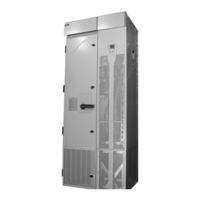
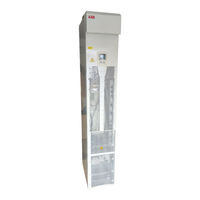
ABB ACS550-U2 Installation Supplement Manual (16 pages)
Drive IT Low Voltage AC Drives 150...550 HP
Brand:
ABB
| Category:
Controller
| Size: 1.6 MB
Table of Contents
Safety
3
General
3
Use of Warnings and Notes
3
Table of Contents
4
Table of Contents
5
Installation
5
Introduction
5
Planning
5
Moving the Unit
5
Mounting
6
Connecting Power and Control Cables
6
Maintenance
9
Safety
9
Separating the Drive and Extension Modules
9
Technical Data
11
Dimensional Drawings
11
Advertisement
Advertisement
Related Products
abb ACS550-CC
ABB ACS550-02
ABB ACS55001/U1
ABB ACS580-0P-06A6-2
ABB ACS580-0P-10A6-2
ABB ACS580-0P-075A-2
ABB ACS580-0P-04A8-4
ABB ACS580-0P-014A-4
ABB ACS580-0P-03A9-6
ABB ACS580-0P-022A-6
ABB Categories
Industrial Equipment
Controller
Measuring Instruments
Battery Charger
DC Drives
More ABB Manuals
Login
Sign In
OR
Sign in with Facebook
Sign in with Google
Upload manual
Upload from disk
Upload from URL