Sign In
Upload
Manuals
Brands
Aaeon Manuals
Motherboard
PICO-BT01
User Manuals: Aaeon PICO-BT01 Single Board Computers
Manuals and User Guides for Aaeon PICO-BT01 Single Board Computers. We have
3
Aaeon PICO-BT01 Single Board Computers manuals available for free PDF download: Manual, User Manual
Aaeon PICO-BT01 User Manual (106 pages)
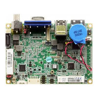
Pico-ITX Board
Brand:
Aaeon
| Category:
Motherboard
| Size: 3 MB
Table of Contents
Table of Contents
11
Chapter 1 - Product Specifications
14
Specifications
15
Chapter 2 - Hardware Information
17
Dimensions
18
Jumpers and Connectors
23
List of Jumpers
25
Clear CMOS Jumper (JP1 1,3,5)
26
Auto Power Button Enable/Disable Selection (JP1 2,4,6)
26
LVDS Port Operating Voltage Selection (JP3)
26
LVDS Port Backlight Inverter Voltage Selection (JP4 1,3,5)
26
List of Connectors
27
Battery (CN1)
28
DDR3L SO-DIMM Slot (CN2)
28
VGA Port (CN3)
28
DP Port (CN4)
29
LVDS Port Inverter / Backlight Connector (CN5)
30
LAN (RJ-45) Port (CN7)
31
Digital IO Port (CN8)
32
Minicard Slot (Full Size)/Default Msata (Feature Select by BOM)
32
(Cn9)
32
USB Ports 0 and 1 (CN10)
35
USB 2.0 Port 2 (CN11)
36
Output for SATA HDD (CN14)
37
SATA Port (CN15)
37
LPC Port (CN18)
38
Front Panel (CN19)
39
External +12V Input (CN20)
39
Buzzer Connector (CN21)
40
BIO Connector (CN22)
40
COM Port 1/2 & Line out Connector (CN23)
42
Minicard Slot (Half-Mini Card) (CN24)
44
LVDS Port (CN25)
47
Chapter 3 - AMI BIOS Setup
49
System Test and Initialization
50
AMI BIOS Setup
51
Setup Submenu: Main
52
Setup Submenu: Advanced
53
Advanced: ACPI Settings
54
Advanced: F81801 Super IO Configuration
56
Super IO Configuration: Serial Port 1 Configuration
57
Super IO Configuration: Serial Port 2 Configuration
58
Advanced: Hardware Monitor
60
Advanced: CPU Configuration
61
CPU Configuration: Socket 0 CPU Information
62
Advanced: SATA Configuration
63
Advanced: Dynamic Digital IO Configuration
65
Advanced: USB Configuration
66
Setup Submenu: Chipset
68
Chipset: North Bridge
69
Chipset: South Bridge
71
South Bridge: Azalia HD Audio
72
South Bridge: USB Configuration
73
South Bridge: PCI Express Configuration
74
Setup Submenu: Security
75
Setup Submenu: Boot
77
Setup Submenu: Save & Exit
78
Chapter 4 - Drivers Installation
79
Product CD/DVD
80
Appendix A - Watchdog Timer Programming
82
Watchdog Timer Registers
83
Watchdog Sample Program
84
Appendix B - I/O Information
87
I/O Address Map
88
B.1 I/O Address Map
88
Memory Address Map
89
IRQ Mapping Chart
90
Appendix C - Electrical Specifications for I/O Ports
102
Electrical Specifications for I/O Ports
103
Appendix D - Mating Connectors
104
List of Mating Connectors and Cables
105
Advertisement
Aaeon PICO-BT01 User Manual (99 pages)
Pico-ITX Board
Brand:
Aaeon
| Category:
Computer Hardware
| Size: 2 MB
Table of Contents
Table of Contents
11
Chapter 1 - Product Specifications
14
Specifications
15
Chapter 2 - Hardware Information
18
Dimensions
19
Jumpers and Connectors
24
List of Jumpers
26
Clear CMOS Jumper (JP1 Pins 1,3,5)
26
Auto Power Button Enable/Disable Selection (JP1 Pins 2,4,6)
26
LVDS Port Operating Voltage Selection (JP3)
27
LVDS Port Backlight Inverter Voltage Selection (JP4 Pins 1,3,5)
27
LVDS Port Backlight Lightness Control Mode Selection (JP4 Pins 2,4,6)
27
List of Connectors
28
Battery (CN1)
29
DDR3L SO-DIMM Slot (CN2)
29
VGA Port (CN3)
29
DP Port (CN4)
30
LVDS Port Inverter / Backlight Connector (CN5)
31
LAN (RJ-45) Port (CN7)
32
Digital IO Port (CN8)
32
Full-Size Mini Card/ Msata Slot (CN9)
33
USB Ports 0 and 1 (CN10)
35
USB 2.0 Port 2 (CN11)
36
Output for SATA HDD (CN14)
36
SATA Port (CN15)
37
LPC Port (CN18)
38
Front Panel (CN19)
39
External +12V Input (CN20)
39
Buzzer Connector (CN21)
40
BIO Connector (CN22)
40
COM Port 1, Port 2 & Line out Connector (CN23)
42
Mini Card Slot (Half-Size) (CN24)
44
LVDS Port (CN25)
46
Chapter 3 - AMI BIOS Setup
48
System Test and Initialization
49
AMI BIOS Setup
50
Setup Submenu: Main
51
Setup Submenu: Advanced
52
Advanced: ACPI Settings
53
Advanced: F81801 Super IO Configuration
55
Super IO Configuration: Serial Port 1 Configuration
56
Super IO Configuration: Serial Port 2 Configuration
57
Advanced: Hardware Monitor
59
Advanced: CPU Configuration
60
CPU Configuration: Socket 0 CPU Information
61
Advanced: SATA Configuration
62
Advanced: Dynamic Digital IO Configuration
64
Advanced: USB Configuration
65
Setup Submenu: Chipset
67
Chipset: North Bridge
68
Chipset: South Bridge
70
South Bridge: Azalia HD Audio
71
South Bridge: USB Configuration
72
South Bridge: PCI Express Configuration
73
Setup Submenu: Security
74
Setup Submenu: Boot
75
Setup Submenu: Save & Exit
76
Chapter 4 - Drivers Installation
77
Driver Download/Installation
78
Appendix A - I/O Information
80
I/O Address Map
81
A.2 Memory Address Map
82
A.3 IRQ Mapping Chart
83
Appendix B - Electrical Specifications for I/O Ports
95
Electrical Specifications for I/O Ports
96
Appendix C - Mating Connectors
97
List of Mating Connectors and Cables
98
Aaeon PICO-BT01 Manual (111 pages)
PICO-ITX Board
Brand:
Aaeon
| Category:
Motherboard
| Size: 4 MB
Table of Contents
Table of Contents
5
Chapter 1 General Information
8
Introduction
9
Features
10
Specifications
11
Chapter 2 Quick Installation Guide
13
Safety Precautions
14
Location of Connectors and Jumpers
15
Mechanical Drawing
17
Heat Spreader Installation
24
List of Jumpers
26
List of Connectors
27
Setting Jumpers
29
Clear CMOS Jumper (JP1 1,3,5)
30
Auto Power Button Enable/Disable Selection (JP1 2,4,6)
30
LVDS Port Operating Voltage Selection (JP3)
30
LVDS Port Backlight Inverter Voltage Selection (JP4 1,3,5)
30
LVDS Backlight Lightness Control Mode Selection (JP4 2,4,6)
31
Battery (CN1)
32
DDR3L SO-DIMM Slot (CN2)
32
VGA Port (CN3)
32
DP Port (CN4)
33
LVDS Port Inverter / Backlight Connector (CN5)
34
LAN (RJ-45) Port (CN7)
35
Digital IO Port (CN8)
36
Minicard Slot (Full Size)/Msata (by BIOS) (CN9)
36
USB Ports 0 and 1 (CN10)
39
USB 2.0 Port 3 (CN11)
41
Output for SATA HDD (CN14)
41
SATA Port (CN15)
42
LPC Port (CN18)
42
Front Panel (CN19)
43
External +12V Input (CN20)
44
Buzzer Connector (CN21)
44
BIO Connector (CN22)
44
Minicard Slot (Half-Mini Card) (CN24)
46
LVDS Port (CN25)
49
COM Port 1/2 & Line out Connector (CN27)
50
Electrical Specifications for I/O Port
53
Chapter 3 AMI BIOS Setup
56
System Test and Initialization
56
AMI BIOS Setup
57
Chapter 4 Driver Installation
85
Installation
85
Appendix A Programming the Watchdog Timer
89
Watchdog Timer Registers
90
Watchdog Sample Program
91
Appendix B I/O Information
94
I/O Address Map
95
Memory Address Map
96
IRQ Mapping Chart
97
Appendix C Mating Connector
109
List of Mating Connectors and Cables
110
Advertisement
Advertisement
Related Products
Aaeon PICO-APL1
Aaeon PICO-KBU4
Aaeon PICO-APL4
Aaeon PICO-WHU4
Aaeon PICO-EHL4
Aaeon PICO-APL2
Aaeon PCM-4896L
Aaeon PCM-4896
Aaeon PFM-540I
Aaeon PCM-5893L
Aaeon Categories
Motherboard
Computer Hardware
Desktop
Touch Panel
Control Unit
More Aaeon Manuals
Login
Sign In
OR
Sign in with Facebook
Sign in with Google
Upload manual
Upload from disk
Upload from URL