Table of Contents
Advertisement
Advertisement
Table of Contents

Related Manuals for Black Horse ZLIN 50LS


Summary of Contents for Black Horse ZLIN 50LS
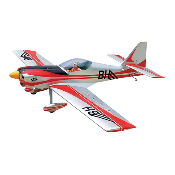
- Page 1 Instruction Manual book ITEM CODE:BH103. SPECIFICATION Wingspan : 2,145 mm 84.45 inches. Length : 1 ,641 mm 64.61 inches. Weight : 5.7 kg 12.54 lbs. ...
- Page 2 Instruction Manual Item code: BH103 This instruction manual is designed to help you build a great flying aeroplane. Please read this manual thoroughly before starting assembly of your ZLIN 50LS. Use the parts listing below to identify all parts. WARNING.
-
Page 3: Safety Precaution
ZLIN 50LS - Instruction Manual Item code: BH103 Caution: this model is not a toy! If you are a beginner to this type of powered model, please ask an experienced model flyer for help and support. If you attempt to operate the model without knowing what you are doing you could easily injure yourself or somebody else. - Page 4 ZLIN 50LS - Instruction Manual Item code: BH103 REPLACEMENT SMALL PARTS 1. Aluminium landing gear. 2. Wheel pants. 3. Wheels. 4. Tail gear set. Aileron. Flap. 5.Engine mount ply of wood . 6. Spinner. 7. Plastic parts for rudder pushrod.
-
Page 5: Installing The Aileron Linkages
ZLIN 50LS - Instruction Manual Item code: BH103 INSTALLING THE AILERON LINKAGES. Installing the aileron linkages as pictures below. 75 mm Repeat the procedure for the other wing half. INSTALLING THE AILERON CONTROL HORN 2x8mm. Secure 3 x 25 mm. -
Page 6: Installing The Engine Mount
ZLIN 50LS - Instruction Manual Item code: BH103 INSTALLING THE FLAP LINKAGES. INSTALLING THE FLAP SERVO. Installing the aileron linkages as pictures 75 mm Electric wire Thread 2x8mm. Secure. Secure. Repeat the procedure for the other wing half. INSTALLING THE FLAP CONTROL HORN. -
Page 7: Installing The Engine
ZLIN 50LS - Instruction Manual Item code: BH103 Mount ply of wood . 3 X 12 mm Drill a hole 4mm diameter. Secure. Left side. INSTALLING THE ENGINE. INSTALLING THE THROTTLE CABLE. 1. Install one adjustable metal connector through the third hole out from the center of... - Page 8 ZLIN 50LS - Instruction Manual Item code: BH103 FUEL TANK. INSTALLING THE STOPPER ASSEMBLY 1. The stopper has been pre-assembled at the factory. 2. Using a modeling knife, cut one length of silicon fuel line (the length of silicon fuel line is...
- Page 9 ZLIN 50LS - Instruction Manual Item code: BH103 Blow through one of the lines to ensure 5. Test fit the stopper assembly into the the fuel lines have not become kinked inside tank. It may be necessary to remove some of the fuel t ank comp artment.
-
Page 10: Installing The Spinner
ZLIN 50LS - Instruction Manual Item code: BH103 Machine screw. Left side. Bottom side. Left side Bottom side. Trim and cut 2. While keeping the back edge of the cowl flush with the marks, align the front of Front view. -
Page 11: Horizontal Stabilizer
ZLIN 50LS - Instruction Manual Item code: BH103 HORIZONTAL STABILIZER. Secure. Secure INSTALLING THE ELEVATOR SERVO. 9 mm Elevator servo 198 mm 1. Install the rubber grommets and brass collets into the elevator servo. Test fit the servo into the servo tray. - Page 12 ZLIN 50LS - Instruction Manual Item code: BH103 Elevator control horn. 2 x 8mm 3 x 15mm Secure. Secure. Elevator Elevator pushrod pushrod ELEVATOR CONTROL HORN AND ELEVATOR PUSHROD INSTALLATION. Elevator control horn install as same as the way of aileron control horn. Please see pic- tures below.
-
Page 13: Vertical Installation
ZLIN 50LS - Instruction Manual Item code: BH103 Plastic parts of elevator pushrod. Aluminium C/A glue A + B Epoxy VERTICAL INSTALLATION. glue. Rudder servo install as same as method of elevator servo. See picture below:... -
Page 14: Rudder Pushrod Installation
ZLIN 50LS - Instruction Manual Item code: BH103 Rudder control horn RUDDER PUSHROD INSTALLATION. 1. Rudder pushrod install as same as the way of aileron control horn. 2. Rudder push - pull system install as same as picture below. -
Page 15: Horizontal Stabilizer Struts
ZLIN 50LS - Instruction Manual Item code: BH103 Secure. C/A glue. Rudder cable Rudder cable R u d d e r Secure. Bottom side pushrod. HORIZONTAL STABILIZER STRUTS. 3 x 15mm. Secure. Secure. -
Page 16: Mounting The Tail Wheel Bracket
ZLIN 50LS - Instruction Manual Item code: BH103 Secure. Secure. Secure. MOUNTING THE TAIL WHEEL BRACKET. 3x12mm 3x15mm MAIN GEAR INSTALATION. PARTS REQUIRED Drill a hole 3mm diameter. -
Page 17: Installing The Switch
ZLIN 50LS - Instruction Manual Item code: BH103 1) Assemble and mounting the wheel p ants as shown in the following pictures. Repeat the process for the other wheel. Bottom side. INSTALLING THE SWITCH. 1. Cut out the switch hole using a modeling ... -
Page 18: Wing Attachment
ZLIN 50LS - Instruction Manual Item code: BH103 INSTALLING THE RECEIVER AND BATTERY. 1. Plug the servo leads and the switch lead into the receiver . You may want to plug an aileron extension into the receiver to make... - Page 19 ZLIN 50LS - Instruction Manual Item code: BH103 Secure. See picture wing attach to fuselage. Wing bolt 6x 70mm. Left side Installing the fuselage hatch as same as picture below. Secure. Drill a hole Drill a hole 3mm diameter 3mm diameter.
-
Page 20: Control Throws
6. Properly balance the propeller. necessary to add weight to the nose or tail to We wish you many safe and enjoy- achieve the proper balance point. able flights with your ZLIN 50LS.
Need help?
Do you have a question about the ZLIN 50LS and is the answer not in the manual?
Questions and answers