Table of Contents
Advertisement
Quick Links
Advertisement
Table of Contents

Related Manuals for Black Horse bravo 3d


Summary of Contents for Black Horse bravo 3d
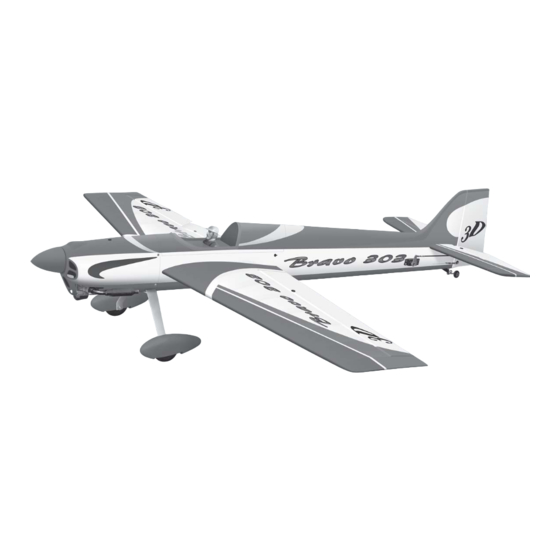
- Page 1 Instruction Manual book SPECIFICATION Wingspan : 1,600 mm 63 in. Length 1,670 mm 65.75 in. Weight 3.6 kg 7.92 Lbs. Radio 06 channels.
- Page 2 BRAVO. INSTRUCTION MANUAL This instruction manual is designed to help you build a great flying aeroplane. Please read this manual thoroughly before starting assembly of your BRAVO . Use the parts listing below to identify all parts. WARNING. Please be aware that this aeroplane is not a toy and if assembled or used incorrectly it is capable of causing injury to people or property.
-
Page 3: Safety Precaution
BRAVO. Instruction Manual SAFETY PRECAUTION. + This is not a toy + Be sure that no other flyers are using your radio frequency. + Do not smoke near fuel + Store fuel in a cool, dry place, away from children and pets. + Wear safety glasses. - Page 4 BRAVO. INSTRUCTION MANUAL 2. Using a modeling knife, remove the cov- Bottom side. ering servo tray. Remove the covering. Bottom of wing. 3) Using the thread as a guide and using C/A glue. masking tape, tape the servo lead to the end of the thread: carefully pull the thread out.
-
Page 5: Instruction Manual
BRAVO. Instruction Manual 2. Drill through 6mm (diameter) the aileron using the control horn as a guide and screw the control horn in place. Secure. Drill a hole 3mm diameter INSTALLING THE AILERON CONTROL HORN. Control horn of Aileron aileron ... -
Page 6: Installing The Aileron Linkages
BRAVO. INSTRUCTION MANUAL INSTALLING THE AILERON LINKAGES. Installing the aileron linkages as pictures below. M3 lock nut Attach the clevis to the outer hole in the con- trol horn. C/A glue. C/A glue C/A glue. Control horn. finishing. Repeat the procedure for the other wing half. -
Page 7: Installing The Engine Mount
BRAVO. Instruction Manual INSTALLING THE ENGINE MOUNT. See pictures below: Mark point. Drill a hole 3mm diameter 3.5x25mm. cut. 4x30mm. -
Page 8: Installing The Stopper Assembly
BRAVO. INSTRUCTION MANUAL FUEL TANK. INSTALLING THE STOPPER ASSEMBLY 5. Test fit the stopper assembly into the tank. It may be necessary to remove some of the flashing around the tank opening using a modeling knife. If flashing is present, make ... -
Page 9: Installing The Engine
BRAVO. Instruction Manual Do not secure the tank into place perma- nently until after balancing the airplane. You may need to remove the tank to mount the battery in the fuel tank compartment. Mark point. C/A glue. Drill a hole 3mm diameter Fuel tank. - Page 10 BRAVO. INSTRUCTION MANUAL Pushrod wire. COWLING. 1. Slide the fiberglass cowl over the en- gine and line up the back edge of the cowl with the marks you made on the fuselage. 2. While keeping the back edge of the cowl flush with the marks, align the front of the cowl with the crankshaft of the engine.
-
Page 11: Installing The Spinner
BRAVO. Instruction Manual INSTALLING THE SPINNER. Secure. Install the spinner backplate, propeller and spinner cone. The spinner cone is held in place using two 3mm x 15mm wood screws. ELEVATOR INSTALLATION. 1. Install the rubber grommets and brass collets into the elevator servo. Test fit the servo into the servo tray. -
Page 12: Horizontal Stabilizer
BRAVO. INSTRUCTION MANUAL HORIZONTAL STABILIZER. 1) Using a modeling knife, cut away the covering from the fuselage for the stabilizer and remove it. Remove covering. See pictures below: Bottom side Elevator servo. C/A glue. C/A glue. - Page 13 BRAVO. Instruction Manual C/A glue. C/A glue. C/A glue. C/A glue. 2. Draw a center line onto the horizontal C/A glue. stabilizer. Then slide the horizontal into the fu- selage. Top side Center line. C/A glue. Check to mark sure the wing and stabi- lizer are paralell.
- Page 14 BRAVO. INSTRUCTION MANUAL 4. Remove the stabilizer. Using the lines you just drew as a guide, carefully remove the covering from between them using a modeling knife. When cutting through the covering to remove it, cut with only enough pressure to only cut through the covering it’s self.
-
Page 15: Elevator Control Horn Installa- Tion
BRAVO. Instruction Manual C/A glue. Drill 1 hole with 6 mm diameter. C/A glue. Drill a hole 3mm diameter ELEVATOR CONTROL HORN INSTALLA- TION. Elevator control horn install as same as the way of aileron control horn. Please see pic- tures below. -
Page 16: Elevator Pushrod Installation
BRAVO. INSTRUCTION MANUAL ELEVATOR PUSHROD INSTALLATION. Elevator pushrod install as same as the way of aileron pushrod. C/A glue. C/A glue. Elevator pushrod. VERTICAL INSTALLATION. Elevator control horn. - Page 17 BRAVO. Instruction Manual See pictures below: C/A glue Control clasp. Hinge. C/A glue C/A glue 1. Using a modeling knife cut away the covering from the horizontal fin for the rudder C/A glue and remove it. 2. Slide the rudder into the fuselage as same as picture below.
-
Page 18: Rudder Control Horn Installa- Tion
BRAVO. INSTRUCTION MANUAL 3. Mark the shape of the vertical on the left and right side on the rudder using a felt-tip pen. Pen. C/A glue. 6) When you are sure that everything is a aligned correctly, mix up a generous amount of 30 minute epoxy. - Page 19 BRAVO. Instruction Manual Control horn of Rudder. C/A glue. M3 lock nut. 3mmx50mm. Nilon control clasp. Drill a hole 3mm diameter C/A glue. Drill 6mm a hole of the mounting rudder control horn on to the rudder with 6mm diam- eter.
-
Page 20: Installing The Throttle Pushrod
BRAVO. INSTRUCTION MANUAL Rudder cable. Elevator pushrod. INSTALLING THE THROTTLE PUSHROD. Install one adjustable metal connector through the third hole out from the center of one servo arm, enlarge the hole in the servo arm using a 2mm drill bit to accommodate the servo connector. -
Page 21: Installing The Switch
BRAVO. Instruction Manual Cut. Switch. INSTALLING THE SWITCH. 1. Cut out the switch hole using a modeling knife. Use a 2mm drill bit and drill out the two mounting holes through the fuselage side. ... - Page 22 BRAVO. INSTRUCTION MANUAL 3. Position the battery pack and receiver behind the fuel tank. Use two tie wraps to hold the battery and receiver securely in place. As pictures below. Do not permanently secure the receiver and battery until after balancing the model.
-
Page 23: Mounting The Tail Wheel Bracket
BRAVO. Instruction Manual Secure. Repeat the process for the other wheel. Secure. 1) The blind nuts are already mounted in- side the fuselage. 2) The holes in the landing gear should be 4) A drop of C/A glue on the wheel collar to accept the mounting bolts. -
Page 24: Wing Attachment
BRAVO. INSTRUCTION MANUAL 1. Set the tail wheel assembly in place on the plywood plate. The pivot point of the tail wheel wire should be even with the rud- der hinge line and the tail wheel bracket should be centered on the plywood plate. - Page 25 BRAVO. Instruction Manual Wing bolt. Secure the canopy frame. Wing bolt. BALANCING. Secure the wing. 1) It is critical that your airplane be bal- anced correctly. Improper balance will cause your plane to lose control and crash. THE CENTER OF GRAVITY IS LOCATED 155mm BACK FROM THE LEADING EDGE OF THE WING.
-
Page 26: Control Throws
BRAVO. INSTRUCTION MANUAL PRE-FLIGHT CHECK. 1. Completely charge your transmitter and 155 mm receiver batteries before your first day of fly- ing. 2. Check every bolt and every glue joint in your plane to ensure that everything is tight and well bonded. - Page 27 BRAVO. Instruction Manual...
Need help?
Do you have a question about the bravo 3d and is the answer not in the manual?
Questions and answers