Advertisement
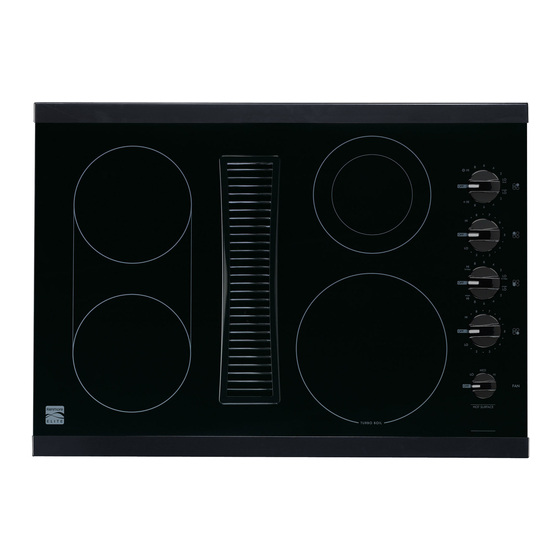
30" RADIANT DOWNDRAFT COOKTOP
CERAMIC GLASS REMOVAL INSTRUCTIONS
TO REMOVE THE CERAMIC GLASS FOR SERVICE:
1. REMOVE THE (10) SILVER/ZINC HEX HEAD SCREWS FROM THE PERIMETER OF THE
BURNER BOX. DO NOT REMOVE THE BLACK HEX SCREWS OR TWO SLOTED HEX SCREWS.
2. CAREFULLY LIFT THE GLASS/TRIM ASSEMBLY FROM THE BURNER BOX.
3. PLACE THE GLASS/TRIM ASSEMBLY ON CARDBOARD OR OTHER PROTECTIVE SURFACE TO
AVOID DAMAGE TO THE GLASS OR THE COUNTERTOP.
724-0409-000-RA 10-11
DO NOT remove
the SLOTTED HEX
screws from the
rear of the unit.
SILVER/ZINC
HEX HEAD SCREW
Advertisement
Table of Contents

Related Manuals for Kenmore 790.44113110


Summary of Contents for Kenmore 790.44113110
- Page 1 DO NOT remove the SLOTTED HEX 30” RADIANT DOWNDRAFT COOKTOP screws from the CERAMIC GLASS REMOVAL INSTRUCTIONS rear of the unit. TO REMOVE THE CERAMIC GLASS FOR SERVICE: 1. REMOVE THE (10) SILVER/ZINC HEX HEAD SCREWS FROM THE PERIMETER OF THE BURNER BOX.
- Page 2 WIRING DIAGRAM / SCHEMATIC DIAGRAM 1. FOR SERVICE REPLACEMENT OF POWER LEADS TO RADIANT BURNERS, KENMORE DOWNDRAFT RADIANT MODELS: 790.44113110, 790.44119110 USE 16 GA, 200°C WIRE. 2. FOR SERVICE REPLACEMENT OF POWER LEADS L1 AND L2, USE 14GA, 125°C WIRE.
Need help?
Do you have a question about the 790.44113110 and is the answer not in the manual?
Questions and answers