
Related Manuals for ACS ACR122L


Summary of Contents for ACS ACR122L
- Page 1 ACR122L Serial NFC Reader with LCD Communication Protocol V1.03 Subject to change without prior notice info@acs.com.hk www.acs.com.hk...
-
Page 2: Table Of Contents
Basic program flow for NFC Forum Type 1 tag applications ..........54 Appendix A. ACR122 Error Codes .................. 56 List of Figures Figure 1 : Communication Flowchart of ACR122L ................. 7 Figure 2 : Character Set A ........................26 Figure 3 : Character Set B ........................27 Figure 4 : Character Set C ........................ - Page 3 Table 5 : Scrolling Period ........................31 Table 6 : Scrolling Direction ........................31 Table 7 : Mifare Ultralight Memory Map ....................49 Table 8 : Mifare Ultralight C Memory Map .................... 53 Page 3 of 57 ACR122L – Communication Protocol info@acs.com.hk www.acs.com.hk Version 1.03...
-
Page 4: Introduction
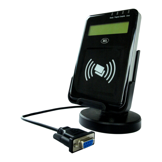
1.0. Introduction The ACR122L serial protocol defines the interface between the PC and reader, as well as the communication channel between the PC and the supported contactless tags/cards – ISO 14443-4 Type A and B, Mifare, ISO 18092 (NFC), and FeliCa. The major applications supported are the following: Access Control, Identification: Reading the serial numbers of all cards in the field. -
Page 5: Features
ISO 14443 VCCI RoHS 2.1. Serial Interface The ACR122L is connected to a Host through the RS232C Serial Interface at 115200 bps, 8-N-1 Signal Function +7 V power supply for the reader (max. 350 mA; normal 200 mA) The signal from the reader to the host. -
Page 6: Leds
Loop inductance is approximately 1.6 μH to 2.5 μH. • Operating distance for different tags, is approximately up to 50 mm (depends on the tag). • Only one tag can be accessed at any one time. Page 6 of 57 ACR122L – Communication Protocol info@acs.com.hk www.acs.com.hk Version 1.03... -
Page 7: Communication Between The Host And Contactless Interface, Sam And Peripherals
ISO 7816 Parts 1-3 ACR122L Contactless Peripherals Interface T=0 SAM Interfaces SAM 1 SAM 2 SAM 3 Interface Contactless Tag (Built-in Antenna) Figure 1: Communication Flowchart of ACR122L Page 7 of 57 ACR122L – Communication Protocol info@acs.com.hk www.acs.com.hk Version 1.03... -
Page 8: Serial Interface (Ccid-Like Frame Format)
4.0. Serial Interface (CCID-like Frame Format) In normal operation, the ACR122L acts as a slave device with regard to the communication between a computer and the reader. The communication is carried out in the form of successive command- response exchanges. The computer transmits a command to the reader, and then receives a response from the reader after the command has been executed. -
Page 9: Protocol Flow Examples
HOST_to_RDR_IccPowerOn HOST_to_RDR_XfrBlock Frames. • RDR_to_HOST_SlotStatus: In response to the HOST_to_RDR_IccPowerOff Frame. RDR = ACR122L; HOST = Host Controller. HOST_to_RDR = Host Controller -> ACR122L RDR_to_HOST = ACR122L -> Host Controller 4.1. Protocol Flow Examples (Use SAM Interface 1 as Example) A. - Page 10 The NAK Frame is only used by the HOST to get the last response. {02 00 00 00 00 00 00 00 00 00 00 00 03} // 11 zeros Page 10 of 57 ACR122L – Communication Protocol info@acs.com.hk www.acs.com.hk...
-
Page 11: Sam Interface
5.0. SAM Interface The ACR122L comes with three SAM interfaces. 5.1. Activating the SAM Interface ACR122L Command Frame Format Bulk-OUT Header Parameters Checksum (HOST_to_RDR_IccPowerOn) 1 Byte 10 Bytes 0 Byte 1 Byte 1 Byte For SAM Interface 1, STX = 02h and ETX = 03h... -
Page 12: Deactivating The Sam Interface
RDR_to_HOST_DataBlock Format Offset Field Size Value Description Indicates that a data block is bMessageType being sent from the ACR122L. dwLength Size of abData field (N Bytes). <LSB .. MSB> bSlot Identifies the slot number for Same as Bulk-OUT this command. - Page 13 Identifies the slot number for this bSlot 00-FFh command. Default=00h. 00-FFh Sequence number for command. bSeq abRFU Reserved for Future Use. ACR122L Response Frame Format Bulk-IN Header abData Checksum (RDR_to_HOST_SlotStatus) 1 Byte 10 Bytes 0 Byte 1 Byte 1 Byte...
-
Page 14: Exchanging Data Through The Sam Interface
63 00 00 00 00 00 02 00 00 00 [Checksum] -> 00 00 -> 81 00 00 00 00 00 02 00 00 00 [Checksum] 5.3. Exchanging data through the SAM Interface ACR122L Command Frame Format Bulk-OUT Header Parameters Checksum (HOST_to_RDR_XfrBlock) 1 Byte... - Page 15 RDR_to_HOST_DataBlock Format Offset Field Size Value Description Indicates that a data block is bMessageType being sent from the ACR122L. dwLength Size of abData field (N Bytes). <LSB .. MSB> bSlot Identifies the slot number for Same as Bulk-OUT this command.
- Page 16 80 0A 00 00 00 00 03 00 00 00 E3 51 B0 FC 88 AA 2D 18 90 00 [Checksum] Response = E3 51 B0 FC 88 AA 2D 18; SW1 SW2 = 90 00 Page 16 of 57 ACR122L – Communication Protocol info@acs.com.hk www.acs.com.hk...
-
Page 17: Pseudo-Apdus For Contactless Interface And Peripherals Control
6.0. Pseudo-APDUs for contactless interface and peripherals control ACR122L comes with two primitive commands for this purpose <Class FFh>. Note: For all the pseudo-APDUs below (except sections 5.2 – Changing the communication speed and 5.3 – Get firmware version), STX MUST BE EQUAL to 02h and ETX MUST BE EQUAL to 03h. - Page 18 InnoVision Jewel tag. This field is not used. Data Out Tag Response returned by the reader. Direct Transmit Response Format Response Data Out D5 41 Status [DataIn[]] Result SW1 SW2 D5 4B NbTg [TargetData1[]] [TargetData2[]] Page 18 of 57 ACR122L – Communication Protocol info@acs.com.hk www.acs.com.hk Version 1.03...
- Page 19 Success The operation is completed successfully. Error The operation is failed. Time Out Error The TAG does not response. Checksum Error The checksum of the Response is wrong. Page 19 of 57 ACR122L – Communication Protocol info@acs.com.hk www.acs.com.hk Version 1.03...
-
Page 20: Change Communication Speed
The APDU Command should be “FF 00 00 00 09 D4 4A 01 01 00 FF FF 01 00” In which, Direct Transmit APDU = “FF 00 00 00” Length of the Tag Command = “09” Page 20 of 57 ACR122L – Communication Protocol info@acs.com.hk www.acs.com.hk Version 1.03... - Page 21 AA 55 AA 55 AA 55 AA [Checksum] 03 RDR -> 02 00 00 03 RDR -> 02 81 11 00 00 00 00 02 00 00 00 Page 21 of 57 ACR122L – Communication Protocol info@acs.com.hk www.acs.com.hk Version 1.03...
- Page 22 “D5 41 00 1D 07 01 01 05 01 86 04 02 02 00 00 01 00 AA 55 AA 55 AA 55 AA 55 AA 55 AA 55 AA 55 AA 90 00” In which, Response returned by the contactless chip = “D5 41” Response returned by the FeliCa Tag = Page 22 of 57 ACR122L – Communication Protocol info@acs.com.hk www.acs.com.hk Version 1.03...
- Page 23 The Composed APDU Command should be “FF 00 00 00 08 D4 40 01 00 84 00 00 08” In which, Direct Transmit APDU = “FF 00 00 00” Page 23 of 57 ACR122L – Communication Protocol info@acs.com.hk www.acs.com.hk Version 1.03...
-
Page 24: Get Firmware Version
For SAM Interface 2 controller, the feedback’s STX = 12h and ETX = 13h For SAM Interface 3 controller, the feedback’s STX = 22h and ETX = 23h Page 24 of 57 ACR122L – Communication Protocol info@acs.com.hk www.acs.com.hk Version 1.03... -
Page 25: Lcd Display (Ascii Mode)
Please follow the DDRAM table below for the LCD character position’s representation. DISPLAY Row\Col POSITION LINE LCD XY POSITION LINE Table 2: DDRAM Address for Font Sets 1 and 2 Page 25 of 57 ACR122L – Communication Protocol info@acs.com.hk www.acs.com.hk Version 1.03... -
Page 26: Figure 2: Character Set A
Note: Size of the characters in Font Set A and Font Set B is 8 x 16, but size of the characters in Font Set C is 8 x 8. Figure 2: Character Set A Page 26 of 57 ACR122L – Communication Protocol info@acs.com.hk www.acs.com.hk Version 1.03... -
Page 27: Figure 3: Character Set B
Figure 3: Character Set B Figure 4: Character Set C Page 27 of 57 ACR122L – Communication Protocol info@acs.com.hk www.acs.com.hk Version 1.03... -
Page 28: Lcd Display (Gb Mode)
Please follow the Fonts table of GB Coding. If ASCII code is to be sent at this mode, the number of characters should be a multiple of 2, otherwise, add 00h after the last character. Page 28 of 57 ACR122L – Communication Protocol info@acs.com.hk www.acs.com.hk Version 1.03... -
Page 29: Lcd Display (Graphic Mode)
7 6 5 4 3 2 1 0 7 6 5 4 3 2 1 0 … 7 6 5 4 3 2 1 0 … … Figure 5: LCD Display Position Total LCD Size: 128 x 32. Page 29 of 57 ACR122L – Communication Protocol info@acs.com.hk www.acs.com.hk Version 1.03... -
Page 30: Scroll Current Lcd Display
1 Unit 3 Units 5 Units 7 Units 17 Units 19 Units 21 Units 23 Units 129 Units 131 Units 133 Units 135 Units 145 Units 147 Units Page 30 of 57 ACR122L – Communication Protocol info@acs.com.hk www.acs.com.hk Version 1.03... -
Page 31: Pause Lcd Scrolling
Pause Scrolling Command Format (5 Bytes) Command Class Pause Scroll LCD Data Out SW1 SW2. Status Code Results Meaning Success The operation is completed successfully. Error The operation is failed. Page 31 of 57 ACR122L – Communication Protocol info@acs.com.hk www.acs.com.hk Version 1.03... -
Page 32: Stop Lcd Scrolling
The operation is completed successfully. Error The operation is failed. Note: For ACR122L firmware versions 307 and above, using the Clear LCD function successively with other LCD functions requires the application to handle an additional 100 ms time delay. 6.11. LCD Backlight Control This command is used to control the LCD backlight. -
Page 33: Lcd Contrast Control
The value range is between 00h (brightest) to 0Fh (darkest). Data Out SW1 SW2. Status Code Results Meaning Success The operation is completed successfully. Error The operation is failed. Page 33 of 57 ACR122L – Communication Protocol info@acs.com.hk www.acs.com.hk Version 1.03... -
Page 34: Led Enable/Disable
1 = On; 0 = Off Bit 2 LED_2 State 1 = On; 0 = Off Bit 3 LED_3 State 1 = On; 0 = Off Bits 4 – 7 Reserved Page 34 of 57 ACR122L – Communication Protocol info@acs.com.hk www.acs.com.hk Version 1.03... -
Page 35: Led And Buzzer Control
Byte 2 Byte 3 T1 Duration T2 Duration Initial Blinking State Toggle Blinking State Number of repetition Link to Buzzer (Unit = 100 ms) (Unit = 100 ms) Page 35 of 57 ACR122L – Communication Protocol info@acs.com.hk www.acs.com.hk Version 1.03... - Page 36 7. The make the buzzer operate, the “number of repetition” must greater than zero. 8. To control the LED only, set the parameter “Link to Buzzer” to zero. Page 36 of 57 ACR122L – Communication Protocol info@acs.com.hk www.acs.com.hk Version 1.03...
- Page 37 APDU = “FF 00 40 04 04 00 00 00 00” Response = “90 02”. LED_0 is not changed (ON); LED_1 is OFF. LED_1 On LED_1 Off LED_0 On LED_0 Off Page 37 of 57 ACR122L – Communication Protocol info@acs.com.hk www.acs.com.hk Version 1.03...
- Page 38 // The buzzer will turn on during the T1 duration, while the LED_0 will turn off during both the T1 and T2 duration. // After the blinking, the LED_0 will turn ON. The LED_1 will resume to the initial state after the blinking // Page 38 of 57 ACR122L – Communication Protocol info@acs.com.hk www.acs.com.hk Version 1.03...
- Page 39 // The buzzer will turn on during both the T1 and T2 duration// LED_1 On LED_1 Off T1 = 500ms T2 = 500ms LED_0 On LED_0 Off Buzzer On Buzzer Off Page 39 of 57 ACR122L – Communication Protocol info@acs.com.hk www.acs.com.hk Version 1.03...
- Page 40 T2 Duration = 500 ms = 05h Number of repetition = 03h Link to Buzzer = 01h APDU = “FF 00 40 D0 04 05 05 03 01” Response = “90 00” Page 40 of 57 ACR122L – Communication Protocol info@acs.com.hk www.acs.com.hk Version 1.03...
-
Page 41: Buzzer Control
Target number = 01 SENS_RES = 00 08; SEL_RES = Length of the UID = 4; UID = 85 82 2F A0 ATS = 07 77 F7 80 02 47 65 Page 41 of 57 ACR122L – Communication Protocol info@acs.com.hk www.acs.com.hk Version 1.03... - Page 42 Step 4. Deselect the Tag. HOST -> 02 6F 08 00 00 00 00 01 00 00 00 (HOST_to_RDR_XfrBlock Format) HOST -> FF 00 00 00 03 D4 44 [Checksum] 03 Page 42 of 57 ACR122L – Communication Protocol info@acs.com.hk www.acs.com.hk Version 1.03...
-
Page 43: Basic Program Flow For Mifare Applications
SEL_RES of some common tag types. 00 = Mifare Ultralight 08 = Mifare 1K 09 = Mifare Mini 18 = Mifare 4K 20 = Mifare DESFire 28 = JCOP30 Page 43 of 57 ACR122L – Communication Protocol info@acs.com.hk www.acs.com.hk Version 1.03... - Page 44 FF 00 00 00 03 D4 44 [Checksum] 03 >> 02 00 00 03 >> 02 80 05 00 00 00 00 01 01 00 00 D5 45 [00] 90 00 [Checksum] 03 Page 44 of 57 ACR122L – Communication Protocol info@acs.com.hk www.acs.com.hk Version 1.03...
-
Page 45: Handling The Value Blocks Of Mifare 1K/4K Tag
Step 3. Transfer the prior calculated value of Block (dec). << 02 6F 0A 00 00 00 00 01 00 00 00 FF 00 00 00 05 D4 40 [Checksum] 03 Page 45 of 57 ACR122L – Communication Protocol info@acs.com.hk www.acs.com.hk Version 1.03... - Page 46 101 (dec). The Adr “05 FA 05 FA” tells us the value is copied from Block 05. Note: Please refer to the MIFARE specification for more detailed information. Page 46 of 57 ACR122L – Communication Protocol info@acs.com.hk www.acs.com.hk Version 1.03...
-
Page 47: Accessing Mifare Ultralight Tags
-> 02 00 00 03 (Waiting the Tag) -> 02 80 05 00 00 00 00 01 01 00 00 -> D5 41 [00] 90 00 [Checksum] 03 Page 47 of 57 ACR122L – Communication Protocol info@acs.com.hk www.acs.com.hk Version 1.03... - Page 48 -> 02 80 05 00 00 00 00 01 01 00 00 -> D5 45 [00] 90 00 [Checksum] 03 Note: Please refer to the Mifare Ultralight specification for more detailed information. Page 48 of 57 ACR122L – Communication Protocol info@acs.com.hk www.acs.com.hk Version 1.03...
-
Page 49: Accessing Mifare Ultralight C Tags
Target number = 01 SENS_RES = 00 44; SEL_RES = Length of the UID = 7; UID = 04 6E 0C A1 BF 02 84 Operation Finished = 90 00 Page 49 of 57 ACR122L – Communication Protocol info@acs.com.hk www.acs.com.hk Version 1.03... - Page 50 -> 02 00 00 03 (Waiting the Tag) -> 02 80 05 00 00 00 00 01 01 00 00 -> D5 41 [00] 90 00 [Checksum] 03 Page 50 of 57 ACR122L – Communication Protocol info@acs.com.hk www.acs.com.hk Version 1.03...
- Page 51 Byte Number Page Serial Number BCC0 Serial Number Internal/Lock BCC1 Internal Lock Lock OTP0 OTP1 OTP2 OTP3 Data read/write Data0 Data1 Data2 Data3 Data read/write Data4 Data5 Data6 Data7 Page 51 of 57 ACR122L – Communication Protocol info@acs.com.hk www.acs.com.hk Version 1.03...
- Page 52 Data132 Data133 Data134 Data135 Data read/write Data136 Data137 Data138 Data139 Data read/write Data140 Data141 Data142 Data143 Lock Lock Lock 16 bit counter 16 bit counter 16 bit counter Page 52 of 57 ACR122L – Communication Protocol info@acs.com.hk www.acs.com.hk Version 1.03...
-
Page 53: Basic Program Flow For Felica Applications
APDU for turning on the Antenna Power = APDU “FF 00 00 00 04 D4 32 01 03” APDU for turning off the Antenna Power = APDU “FF 00 00 00 04 D4 32 01 02” Page 53 of 57 ACR122L – Communication Protocol info@acs.com.hk www.acs.com.hk... -
Page 54: Basic Program Flow For Nfc Forum Type 1 Tag Applications
Note: To update more than one memory content of the tag starting form the memory address (Block 1: Byte-0). HOST -> 02 6F 0D 00 00 00 00 01 00 00 00 FF 00 00 00 08 D4 40 AA BB [Checksum] Page 54 of 57 ACR122L – Communication Protocol info@acs.com.hk www.acs.com.hk Version 1.03... -
Page 55: Version 1.03
HOST -> 02 6F 08 00 00 00 00 01 00 00 00 FF 00 00 00 03 D4 44 01 [Checksum] 03 -> 02 00 00 03 02 80 05 00 00 00 00 01 01 00 00 D5 45 [00] 90 00 [Checksum] 03 Page 55 of 57 ACR122L – Communication Protocol info@acs.com.hk www.acs.com.hk... -
Page 56: Appendix A. Acr122 Error Codes
ISO/IEC 14443-3B only: the ID of the card does not match, meaning that the expected card has been exchanged with another one. ISO/IEC 14443-3B only: the card previously activated has disappeared. Page 56 of 57 ACR122L – Communication Protocol info@acs.com.hk www.acs.com.hk Version 1.03... - Page 57 Error Code Error Mismatch between the NFCID3 initiator and the NFCID3 target in DEP 212/424 kbps passive. An over-current event has been detected. NAD missing in DEP frame. Page 57 of 57 ACR122L – Communication Protocol info@acs.com.hk www.acs.com.hk Version 1.03...
Need help?
Do you have a question about the ACR122L and is the answer not in the manual?
Questions and answers