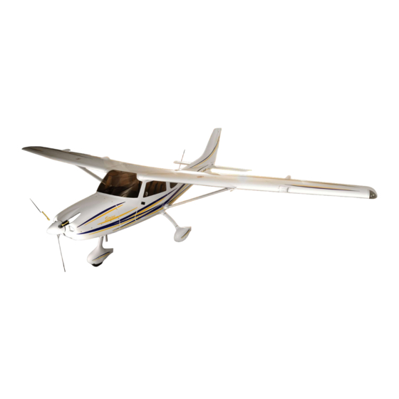
TL Ultralight TL-3000 Sirius Maintenance Manual
Hide thumbs
Also See for TL-3000 Sirius:
- Pilot operating handbook (62 pages) ,
- Flight and operation manual (68 pages) ,
- Flight and operational manual (64 pages)
Table of Contents
Advertisement
Advertisement
Table of Contents

Subscribe to Our Youtube Channel
Related Manuals for TL Ultralight TL-3000 Sirius


Summary of Contents for TL Ultralight TL-3000 Sirius
- Page 1 Sirius TL-3000 AIRCRAFT MAINTENANCE MANUAL Ing. Martin Zahálka Ph.D Author: THIS DOCUMENT AND TECHNICAL DATA HEREON DISCLOSED ARE PROPRIETARY TO TL-ULTRALIGHT AND SHALL NOT BE USED, RELEASED OR DISCLOSED IN WHOLE OR IN PART WITHOUT EXPRESS WRITTEN PERMISSION FROM TL-ULTRALIGHT.
- Page 2 (THIS PAGE BLANK) 0 - 0...
- Page 3 Dear Sirius Owner: Congratulations on the purchase of your Sirius! You will find your new TL-ULTRALIGHT aircraft very enjoyable, extremely economical, and easy to maintain. The Sirius is the ideal Light Sport Airplane. It is fast, economical, pleasing to the eye, and user friendly. We at TL-ULTRALIGHT Sport Aircraft are certain that your Sirius will give you hours and hours of leisure flying and enjoyment.
- Page 4 (THIS PAGE BLANK) 0 - 2...
-
Page 5: Table Of Contents
0.1 Table of Content ...........0-2 0. ITRODUCTION 0.1. Table of Content ...........0-4 0.2. Notes, Cautions, and Warnings ...........0-8 0.3. List of Revisions ...........0-10 ...........1-1 1. GENERAL INFORMATION 1.1. Introduction ...........1-1 1.1.1 Scope ...........1-1 1.1.2 Safety ...........1-1 1.1.3 Referenced Documents ...........1-2 1.1.4 Definitions ...........1-2 1.1.5 Maintenance and Repair... -
Page 6: Table Of Contents
...........3-1 3. STRUCTURES 3.1 Introduction ...........3-1 3.2 Wing ...........3-1 3.2.1 Wings Installation ...........3-3 3.2.2 Wings Removal ...........3-22 3.2.3 Verification Required ...........3-22 3.3 Empennage ...........3-23 3.3.1 Horizontal tail Installation ...........3-24 3.3.2 Horizontal tail Removal ...........3-33 3.3.3 Elevator Installation ...........3-33 3.3.4 Elevator Removal ...........3-41 3.3.5 Verification Required (horizontal tail and elevator... -
Page 7: Table Of Contents
3.4.20 Replacing/removal of the Brake pads – 15 x 6 wheels ...........3-134 3.4.21 Verification Required (Replacing/removal of the Brake pads) ...........3-141 3.5 Structural Control Surfaces ...........3-142 3.5.1 Flap installation ...........3-143 3.5.2 Flap Removal ...........3-147 3.5.3 Verification Required (flap installation / removal) ...........3-147 3.5.4 Setting Flap „Zero“... -
Page 8: Table Of Contents
3.11.5 Inspection and operation checks ...........3-199 3.12. Structural Repair ...........3-200 3.12.1 Repair of Laminate parts ...........3-200 3.13 Painting and Coating ...........3-203 3.13.1 Paint repairs ...........3-203 3.13.2 Paint repairs – Method of Verification ...........3-208 3.14. Securing bolted connections ...........3-208 3.14.1 General ...........3-208 3.14.2 Cotter Pins ...........3-208... -
Page 9: Notes, Cautions, And Warnings
0.2 Notes, Cautions, and Warnings Throughout this manual, small boxes are inserted reading Note, Caution, or Warning. These are items which require particularly close attention for special conditions or procedures. NOTE This text box emphasizes specific operating conditions, steps in a procedure, helpful hints or useful advice. - Page 10 CAUTION The Sirius is intended for sport and recreational purposes only. This aircraft meets the standard specification Design and Performance (D&P) established by the American Society for Testing and Materials (ASTM) Document F 2245 -11, and it is therefore restricted by that guideline.
-
Page 11: List Of Revisions
0.3 List of Revisions TL-ULTRALIGHT The Revisions pages are updated by each time revision issued. They contain a list of all revisions made to the Maintenance Manual since its original issue. Date Revised Type of Revision Posted Pages 30 August 2010 None Original Issue New type of... - Page 12 (THIS PAGE BLANK) 0 - 10...
-
Page 13: General Information
SECTION 1 GENERAL INFORMATION 1.1 Introduction Section 1 contains general information regarding manual organization, descriptive data, abbreviations, the Master Equipment List, ‘feed-back’ forms for the aircraft and this manual as well as current warranty information. This manual is written to conform to the ASTM F2483-05, Maintenance and the Development of Maintenance Manuals for Light Sport Aircraft. -
Page 14: Referenced Documents
1.1.3 Referenced Documents ASTM Standards: F 2245 Specification for Design and Performance of a Light Sport Airplane F 2295 Practice for Continued Operational Safety Monitoring of a Light Sport Airplane Federal Standards: 14 CFR Part 21.190 Issue of a Special Airworthiness Certificate for a Light-Sport Category Aircraft 14 CFR Part 43 Maintenance, Preventive Maintenance, Rebuilding, and Alteration 14 CFR Part 65 Certification: Airmen Other Than Flight Crewmembers... - Page 15 LSA (light sport aircraft)—aircraft designed in accordance with ASTM standards under the jurisdiction of Committee F37 Light Sport Aircraft. LSA repairman inspection—U.S. FAA-certificated repairman (light sport aircraft) with an inspection rating as defined by 14 CFR Part 65, authorized to perform the annual condition inspection on experimental light sport aircraft, or an equivalent rating issued by other civil aviation authorities.
-
Page 16: Maintenance And Repair
1.1.5 Maintenance and Repair Inspection or Repair, —Each of the inspections or repairs outlined in the maintenance manual specifically list: (1) Recommended special tools to accomplish the task, if any (2) The parts needed to perform the task, if any (3) Type of maintenance, line (L), heavy (H), or overhaul (OV) (4) The level of certification needed to accomplish the task, owner (O), (light sport aircraft) inspection (RI), (light sport aircraft) repairman (RM), FAA approved A&P (A&P),... -
Page 17: Line Maintenance And Repairs
Task Not Specified—The aircraft is to be maintained, serviced and repaired in accordance with this manual and the equivalent maintenance manual provided by the manufacturer of all other components not manufactured by TL-ULTRALIGHT. In the absence of specific instructions for a repair in one of the above mentioned maintenance manuals, and where such repairs are not restricted by these manuals or listed as Overhaul, Alteration,... -
Page 18: Overhaul
Typical Tasks Considered as Heavy Maintenance include: Removal and replacement of components for which instructions are provided in the maintenance manual or service directive instructions, such as: Complete engine removal and reinstallation in support of an engine overhaul or to install a new engine, Remove and replacement of engine cylinders, pistons, or valve assemblies, or a combination thereof,... -
Page 19: Task – Specific Training
No changes may be made to any TL-ULTRALIGHT aircraft without prior written approval of TL-ULTRALIGHT. Any changes made without TL-ULTRALIGHT written approval will void the aircraft airworthiness certificate. TL-ULTRALIGHT may authorize another TL-ULTRALIGHT approved entity to perform the evaluation of an alteration, modification or major repair who shall provide a written affidavit that the aircraft being altered will still meet the requirements of the applicable ASTM design and performance specification after the alteration. - Page 20 SLSA and components installed on SLSA’s do not have Airworthiness Directives issued against them. If an AD is issued against a type-certificated product that may be incorporated into special light sport aircraft, T TL-ULTRALIGHT will issue a safety directive in accordance with Document F 2295 41 to provide instruction on how to address the safety defect outlined in the AD on the specific SLSA.
-
Page 21: Views, Dimensions
1.1.12 Views, dimensions 1 - 9... - Page 22 Basic dimensions: ………… 22.87 ft. Maximum length ...………. 3.94 ft. Cabin width ………… 30.84 ft. Wing Span ………… 7.38 ft. Height Areas: Wing ..……… 120.06 ft ……….. 14.21 ft Flaps ……….. 4.46 ft Rudder ……….. 21.64 ft Stabilizer Aspect ratio: ……………...
-
Page 23: Aircraft Specifications
1.1.13 Aircraft Specifications The Sirius is a full three axis, high wing; two place side-by-side seating, tricycle landing gear aircraft with a steerable or non-steerable nose wheel (depends on version). The primary aircraft structure is carbon fiber and fiberglass UV resistant reinforced laminate with an inner foam core creating a ‘sandwich’... -
Page 24: Propeller Specifications
Oil temeprature: 140°C (285°F) 130°C (266°F) 130°C (266°F) Maximum 50°C (120°F) 50°C (120°F) 50°C (120°F) Minimum Cylinder head temperature 150°C 135°C Maximum cylinder head temperature (300°F) (284°F) Coolant temperature: 120°C 120°C 120°C Maximum coolant temperature (248°F) (248°F) (248°F) Engine start, operating temperature 50°C (120°F) 50°C (120°F) 50°C (120°F) -
Page 25: Structural Materials
1.1.16 Structural Materials Non-metal materials Material Description Supplier Supplier article number Epoxy resin L-285 Skolil kompozit s.r.o. Hardener 285 Skolil kompozit s.r.o. Hardener 287 Skolil kompozit s.r.o. Hardener C Havel Composites CZ s.r.o. Epoxy flokes BAUMWOLLEFLOCKEN Skolil kompozit s.r.o. L+R0025 Epoxy flokes GLASS Bubbles Q-Cell 2106 Skolil kompozit s.r.o. -
Page 26: List Of Disposable Replacement Parts
Metal materials Material Description Source of mechanical properties ČSN 41 1323 Steel 11 323 ČSN 41 1353 Steel 11 353 ČSN 41 1523 Steel 11 523 ČSN 41 5130.1 High-tensile steel 15 130.1 Chromium – molybdenum steel 4130 ČSN 41 7153 Stainless steel 17 153 Stainless steel EN ISO 9445 EN 10088-2... -
Page 27: Aircraft And Engine Approved Equipment
DIAFRICT 400 x 100 mm Brake pads on condition 2057163605590 wheels 400 x 100 mm Brake disc on condition Brake system wheels parts DIAFRICT 2057163607170 400 x 100 mm Brake pads on condition size wheels 2057163607180 15 x 6 size Brake disc S4-350_000_00-1 on condition... - Page 28 approved under the written authority of TL-ULTRALIGHT or the U. S. Field Technical Director. TL 3000 Sirius Master Equipment List Engine Item Description Manufacturer Model Engine Rotax 912UL Engine Rotax Engine Rotax 912ULS Engine Rotax 912S Engine Oil Filter Rotax (No Substitutes!) 825-701 Engine Oil Drain Filter TL-ULTRALIGHT...
- Page 29 TL 3000 Sirius Master Equipment List Equipment Item Description Manufacturer Model Towing Bar TL-ULTRALIGHT Parachute System Galaxy GRS 6–1350SD LSA Door Lock (2x) TL-ULTRALIGHT Seat (2x) TL-ULTRALIGHT 3-points safety belts (2x) Schroth Rallye 3 asm Cockpit Upholstery TL-ULTRALIGHT Baggage Area Upholstery TL-ULTRALIGHT Cargo Net TL-ULTRALIGHT...
- Page 30 TL 3000 Sirius Master Equipment List Communication and Instrumentation Item Description Manufacturer Model VHF Radio Icom 200A VHF Radio Icom 210A 2.25˝ VHF Radio MicroAir VHF Radio Becker AR4201 VHF Radio Funkwerk ATR833 VHF Antenna KONS ULA 1L 18 VHF Antenna Comant CI-121 Transponder...
- Page 31 TL 3000 Sirius Master Equipment List Communication and Instrumentation Item Description Manufacturer Model AutoPilot System, Steering Tru Trak ADI P1 AutoPilot System, Altitude Tru Trak ADI P2 AutoPilot System, Altitude Dynon Avionics AP74 GPS Navigation System Garmin GPS Navigation System Garmin GPS Navigation System Garmin...
-
Page 32: Weight And Balance Information
1.1.19 Weight and Balance Information Section includes the allowed centre of gravity positioning and weight ranges and centre of gravity position determination procedure allowing safe aircraft operating. All aircraft are structurally and aerodynamically engineered for certain load conditions which result from specific weights and forces anticipated to occur in normal operations An Aircraft’s handling qualities and structural within the specified flight envelope. - Page 33 Center of Gravity Limits are the extreme forward and aft center of gravity locations (limits) within which the airplane must be operated at any given weight. Center of Gravity Range: The horizontal distance, along an aircraft’s longitudinal axis, within which an aircraft has been found to be fully maneuverable at all specified design speeds, weights and loading configurations.
- Page 34 Weight: Actual individual weight of each item such as airframe, crew, fuel, baggage, cargo, etc. in pounds or kilograms Empty Weight: The actual weight of the individual aircraft, including the structure, power plant, fixed equipment, any fixed ballast, unusable (in-flight) fuel, and coolant. Original Empty Weight is determined by actually weighing each new aircraft before it is flown.
- Page 35 Be sure to remove any loose equipment, tools, etc. from the aircraft prior to weighing. Sometimes it is necessary to adjust or reduce fuel, cargo, or passenger weights to remain at or below Maximum Allowable Gross Weight. Temporary or permanent ballast is sometimes necessary to bring the C.G.
- Page 36 EMPTY WEIGHT CENTER OF GRAVITY CALCULATIONS Item Dimension (inches) 32.49 25.98 1.38 48.43 Read the G and G values from the scales (G represents the sum of the values indicated by the scales under the main wheels). Calculate the total empty aircraft weight by using the following formula: ...
- Page 37 Calculate the empty aircraft centre of gravity position in %MAC: LOADED WEIGHT AND BALANCE CALCULATIONS Find the empty aircraft weight G and empty aircraft centre of gravity position EmptyAircraft %EmptyAircraft Determine the weight of the onboard items for the required configuration: Item Description Crew weight...
- Page 38 Calculate the empty aircraft centre of gravity for the required configuration (by inserting the values): WARNING WARNING RNING The calculate x value must fit within the centre of gravity positioning range from %Aicraft 22 to 32,5 %MAC CRITICAL LOADING CONDITIONS Each of the following critical loading conditions should be investigated for each individual aircraft, along with any other possible loading condition which may affect the Weight and Balance envelope of the aircraft.
-
Page 39: Tire Inflation Pressure
WEIGHT & BALANCE DATA WORKSHEET NOTES Datum Plane: Wing leading edge. Maximum Forward CG Limit: 12.03 inches aft of Datum Maximum Aft CG Limit: 17.12 inches aft of Datum Maximum Gross Weight: 1320 pounds Maximum Seat Load: 240 pounds Minimum Pilot Weight: 100 pounds Maximum Fuel: 206 pounds Maximum Baggage Weight: 65 pounds 1.1.20... -
Page 40: Recommended Fastener Torque Values
Fuel Fuel content: (2 wing fuel tanks for 65 l) 34.32 U.S. gal (130l) Maximum fuel available: 33.79 U.S. gal (128 l) Fuel consumption: max. 7.13 U.S. gal/h (27 l/h) Braking fluid: DOT 4 or DOT 5 Brake fluid, it depends on type of brake cylinders (see chapter 3.4.15) Cooling fluid: Antifreeze Extra CAUTION... -
Page 41: General Safety Information
1.1.23 General Safety Information WARNING WARNING RNING During all service and repair work beware of activating the Ballistic Parachute systém rocket. 1 - 29... -
Page 42: Report „Feed Back" Forms
WARNING WARNING RNING An accidental engine start is very dangerous. Ensure that the Ignition Switches and main switch are turned off. Report ˝Feed Back˝ Forms 1.1.24 The following pages contain ‘feed-back’ reports that are intended to assist the owner in reporting questions, safety issues, service or maintenance issues, parts and assembly performance, incidences and warranty claims which may assist in the safe operation of our aircraft and the use of this manual. - Page 43 Aircraft / Part / Assembly/ Incident Safety Feed Back Form: Report Date: Aircraft N Number: Aircraft S/N: Flight hours: Report Airport: Aircraft Airport: Conditions: 1. Periodic Inspection Notes (circle ) 2. Pre-flight Inspection 3. Engine Start 4. Taxi 5. Take off 6.
- Page 44 Aircraft Maintenance & Maintenance Manual Feed Back Form: Report Date: Manual Section: 0. Introduction 1. General (circle) 2. Inspections 3. Structures 4. Engine 5. Fuel System 6. Propeller 7. Utility Systems 8. Instruments and Avionics 9. Electrical System 10. Painting and Coatings Page Number: Subject Heading: Description: (errata;...
- Page 45 Example of report below, see following page for Warranty Claim Report form. 1 - 33...
- Page 46 1 - 34...
- Page 47 INSERT WARRANTY HERE! 1 - 35...
-
Page 48: Inspections
SECTION 2 INSPECTIONS 2.1 Introduction Section 2 contains information pertaining to light maintenance, the weight and balance calculations and periodic inspection lists for the airplane. Included is a illustrated parts list grouped by category and at the end of this section are detailed checklists of the periodic inspections which are meant to be copied and the copy used as a checklist for the inspection. -
Page 49: Washing And Cleaning The Airplane
2.3 Washing and Cleaning the Airplane Line Type of Maintenance L/O, RI, RM, A& P Level of Certification Required Tools Required Vacuum cleaner, Chamois leather Materials Required Lukewarm water, Cleansing agents used for cleaning and protecting automobiles Washing and Cleaning Checklist After each flight day Once a mounth □... -
Page 50: Filling The Fuel Tank
2.4 Filling the Fuel Tank Due to the composite construction of the airplane, static electricity may occur. CAUTION Fill the fuel tank only from an approved storage container using a funnel approved for petrol only. The tank should be fastened to the ground with a grounding pin (do not use plastic fuel cans or funnels that are not certified for petrol). - Page 51 Type of Maintenance Line Level of Certification Required L/O, RI, RM, A& P Tools Required Funnel with water separator Materials Required The Fuel Tank filling Checklist □ Electrical appliances. Turn off all electrical appliances, cell phones, ignition circuits and the main switch.
-
Page 52: Engine Visual Inspection
2.5 Engine Visual Inspection Line Type of Maintenance L/O, RI, RM, A& P Level of Certification Required Tools Required Screw driver Materials Required Fuel filter, Engine Oil, Engine Cooling Fluid Engine Visual Inspection Checklist Before each flight day □ Switches. Ensure that the Ignition Switches and Main Switch are turned off. -
Page 53: First 25H / 50H / 100H / Annual Inspection
2.6 First 25h / 50h / 100h / Annual Inspection 2.6.1 FAA Required Inspections As required by Federal Aviation Regulations, all LSA aircraft of U.S. registry must undergo a complete condition inspection (“annual”) every twelve calendar months, in addition, every 100 hours of operation when operated in commercial use. It is the responsibility of the owner/operator to assure compliance with all applicable aircraft manufacturer directives. -
Page 54: Every 50H / 100H / Annual Inspection
2.6.3 Every 50h / 100h / Annual Inspection The inspection after every 50 flight hours is performed in conjuction with the engine oil and filter change by the airplane owner if he is trained for the airplane´s maintenance or by an FAA qualified inspector following the 50 hour inspection checklist. If the aircraft is used for commercial operation the inspection is performed by an FAA approved A&P. - Page 55 Condition inspection checklist TL – 3000 Sirius Aircraft Model / Serial Number Registration Number Owner´s Name Inspector´s Name Date of Inspection Engine Model / Serial Number Airframe Hours Engine Hours Condition inspection checklist Inspection Item 50 hour 100 hour Annual □...
- Page 56 Run-up checklist Type of Inspection 50 hour 100 hour Annual ELT battery due (if applicabe): Altimeter/Transponder test due (if applicabe): Strobe lights test due (if applicabe): Systems Pre - inspection Post - inspection □ □ Starter □ □ Oil pressure (PSI) □...
- Page 57 Post – Run - up checklist Inspection Item 50 hour 100 hour Annual □ □ □ Flight controls. Check for smooth operation of all flight controls with flaps in retracted and extended positions. □ □ □ Flight controls. Check controls within entire range for binding, play, and unusual sounds.
- Page 58 Inspection Item 50 hour 100 hour Annual □ Cabin heater. Check clamps and heater attachments. Check the manifold for holes and attachments. □ □ Engine mount. Inspect for cracks, corrosion, loose hardware, chafing by cables, wires, hoses, etc., and make sure that any flexing item is secured to the engine mount.
- Page 59 Inspection Item 50 hour 100 hour Annual □ □ Static Port. Check static port for evidence of obstructions. Do not apply compressed air to the system, since this will result in damage to the static air flight instruments. □ Antennas. Inspect for security and condition. □...
- Page 60 Inspection Item 50 hour 100 hour Annual □ □ □ Flaps. Inspect skins for condition and signs of debonding. Check hinges for play and attachment to wing and flap. Check flap rod and rod tips for condition, and lubricate (see Chapter 2.8). Check for obstruction of drain holes.
- Page 61 Inspection Item 50 hour 100 hour Annual □ □ □ Horizontal Stabilizer and Elevator. Inspect for visible damage and evidence of latent damage. Inspect looseness or play in hinges. Check for obstruction of drain holes. Check suspension and free travel of the elevator. □...
- Page 62 Inspection Item 50 hour 100 hour Annual □ □ Wheel bearings. Inspect for damage, wear, and corrosion. Check bearing for play, binding and bearing protection plate for condition. Replace bearings if necessary. □ □ Nose landing gear. Lift up the nose gear and check rotation of the nose gear.
- Page 63 Inspection Item 50 hour 100 hour Annual □ Magnetics compass. Inspect compass correction card for presence and legibility of all headings. Magnetic tools must not be used during this procedure. □ □ Fuel valve. Inspect for operating and signs of fuel leakage.
- Page 64 Inspection Completion Inspection Item 50 hour 100 hour Annual □ □ □ Fuselage and wings. Make sure aircraft is free of any tools, parts, and debris, and reinstall all access panels, fairings, seats, and so on, removed for the inspection. □...
-
Page 65: Every 300 Hour Inspection
2.7 Every 300 hour Inspection This inspection is made after every 300 flight hours, or after five years of operation. The inspection of all stressed parts of the construction is made along with the prescribed repair according to the manufacturer’s guide book. The inspection and maintenance include: ... -
Page 66: Lubrication Program Figures
2.9 Lubrication program figures 2 - 19... - Page 67 2 - 20...
- Page 68 2 - 21...
- Page 69 2 - 22...
-
Page 70: Structures
Sirius serial numbers. 3.2 Wing The wing of TL-3000 Sirius consists of right and left wings (made of carbon and fiberglass parts bonded together with structural epoxy resin) and left and right struts. - Page 71 The wing structure includes the skins (upper and lower), main and rear spar, fuel tank, and ribs. The hinges for aeileron and flap are attached to the lower skin and rear spar along the trailing edge. The aileron and flap control rods runs between the spars. Two fuel filler caps are on the upper wing surface.
-
Page 72: Wings Installation
3.2.1. Wings Installation To install the wings requires two - three persons. Contact TL-ULTRALIGHT or an authorized dealer for the instructions on wing installation, if installing a replacement wing, or a repaired wing. Type of Maintenance Line Level of Certification Required L/O, RI, RM, A&... - Page 73 3) Aerodynamic struts covers. Slip on the struts the Strut – fuselage covers [s200_577_00-1] and Wing – strut covers [s200_577_00-1]. Pos. Part Part number / Norm Strut s810_000_00-1 Wing – strut cover s810_300_00-1 Strut – fuselage cover s810_400_00-1 4) Fuselage – struts connecting. Fix the bottom struts bearings in the Strut – fuselage fittings [s200_810_00-1] (2x left and right) with the bolt M10x50 DIN 912.
- Page 74 Pos. Part Part number / Norm Strut – fuselage fitting s200_810_00-1 Strut s810_000_00-1 Strut – fuselage cover s810_400_00-1 Screw M10 x 50 DIN 912 ČSN 02 1721 Washer M10 Self – locking nut VM 10 DIN 980 CAUTION Keep the struts position. Strut mount with indications arising from the dismantling of the wings. 3 - 5...
- Page 75 5) Wing assembly. Put the wing with the hinges into the fuselage holes with clearance aprox. 0.12 ft betweem the fuselage and the wing root rib. Run all fuel hoses and electrical wires into the cabin. Then push the wing into the fuselage. CAUTION Keep holding the wing tip or use the cradles for the wings until the strut is conected.
- Page 76 6) Main and rear pins connection . Fix the main and rear wing hinges to the fuselage with the bolts M10x50 DIN 912 and M8x50 DIN 912. Use only new self-locking nuts VM10 and VM8. 3 - 7...
- Page 77 Pos. Part Part number / Norm Screw M8 x 32 DIN 912 Screw M10 x 50 DIN 912 ČSN 02 1721 Washer M8 ČSN 02 1721 Washer M10 Self – locking nut VM 8 DIN 980 Self – locking nut VM 10 DIN 980 3 - 8...
- Page 78 7) Wing – strut connecting . Fix the upper struts bearings in the Wing – strut fitting [s110_430_00-1] with the bolt M10x50 DIN 912. Use only new self-locking nuts VM10. Pos. Part Part number / Norm Wing - strut fitting s110_430_00-1 Strut s810_000_00-1...
- Page 79 8) Wing connection control. Note that the screws can be set properly into the bushings by moving of the wing back and forth and up and down. 3 - 10...
- Page 80 9) Connecting ailerons control. Fix the Wing inner pullrod assembly [s523_400_00-1] in the Upper lever pillar assembly [s522_800_00-1] with the screw M6 x 27 DIN 912. Use only new self-locking nuts VM6. Check ailerons deflection. Pos. Part Part number / Norm Screw M6 x 27 DIN 912 ČSN 02 1721...
- Page 81 10) Fuselage-to-wing wiring. Connect all fuselage-to-wing wiring, i.e. connect the flaps actuator, position and strobe lights socket and plug. 11) Fuselage-to-wing grounding. Connect fuselage-to-wing grounding wire. 3 - 12...
- Page 82 12) Fuel feed line. Connect the fuel feed line from the wing to the fuselage, i.e. set the fuel hose onto the pipe, having the 12 mm clamp on it. Attach the fuel hose by the 12 mm clamp. Pos. Part Part number / Norm Fuselage pipe...
- Page 83 14) Second wing. Repeat the same previous steps on the second wing. 15) Flaps drive in the fuselage. Link the flaps drive in the wings in the fuselage, i.e. insert Flaps drive in the fuselage assembly. Match groove on the Flap drive tenon [s541_620_00-1] with the screw M5 x 27 DIN 912 on the Short and Long tube [TR20x1-72 (42 4201.61) and TR20x1-960 (42 4201.61)].
- Page 84 16) Flaps drive in the fuselage fixing. Fix the Long tube [TR20x1-72 (42 4201.61)] in the Flap drive joint in the fuselage [s542_200_00-1] with the screw M5 x 27 DIN 912. Use only new self-locking nuts VM5. 3 - 15...
- Page 85 Pos. Part Part number / Norm Flap drive joint in the fuselage s542_200_00-1 Long tube TR20x1–960 (42 4201.61) Screw M5 x 27 DIN 912 Self – locking nut VM 6 DIN 980 17) Flaps drive screws tightening. Tighten two screws M5 x 27 DIN 912 fixing the Flap drive tenon [s541_620_00-1] and Short and Long tube [TR20x1-72 (42 4201.61) and TR20x1-960 (42 4201.61)].
- Page 86 Pos. Part Part number / Norm Center plastic bearing bushing s542_310_00-1 Center plastic bearing socket s542_320_00-1 Center plastic bearing distance s542_330_00-1 Long tube TR20x1–960 (42 4201.61) Screw M5 x 20 PN 02009 19) Flaps deflection. Ensure that flaps equally on each side of the airplane in all configurations. Measure the down deflection on each side.
- Page 87 20) Securing bolted connections. Secure all bolted connections by the F-900 Torque seal. 21) Canopy ceiling cover. Fix on the Velcro the Ceiling cover – laminate [s200_661_00-1]. Ceiling panel board with the switches and radio run through the hole in the ceiling laminate cover (if is ceiling panel board applicable).
- Page 88 22) Fuel gauge installation. Instal left and right fuel tank fuel gauges, i.e. fix Inner part of the fuel gauge [s200_663_20-1] and Outer part of the fuel gauge [s200_663_30-1] on the Ceiling cover – laminate [s200_661_00-1] with four screws M4 x 12 DIN 965 Zn (insert Fuel gauge transparency cylinder [s200_663_10-1] to the assembly).
- Page 89 23) Canopy ceiling cover fixation. Fix Ceiling cover – laminate [s200_661_00-1] with teen slotted mushroom head screws M4 x 12 (905624). 24) Canopy ceiling cover fixation. Fix Ceiling panel board with switches a radio on the Ceiling cover - laminate [s200_661_00-1] with seven black colored phil. pan head machine screws M4 x 12 DIN 7985 (if is ceiling panel board applicable).
- Page 90 25) Pillar inspection holes covers. Close four inspection holes in the pillar using holes covers. Fix inspection holes covers on the pillar with screws M2,9 x 10 DIN 7981 Zn (two screws per cover). 3 - 21...
-
Page 91: Wings Removal
26) Aerodynamic struts covers fixation. Fix Strut – fuselage covers [s200_577_00-1] and Wing – strut covers [s200_577_00-1] on the fuselage and wing with slotted mushroom head screws M4 x 12 (905624). 3.2.2. Wings Removal Drain all the fuel from the wings and fuel lines. The process of draining the aircraft should be performed in a ventilated area with fire precautions taken. -
Page 92: Empennage
3.3 Empennage Sirius empennage consists of a vertical fin with a rudder and horizontal tail. The fin makes up a one piece composite structure with the fuselage and therefore is not considered within this section. Horizontal tail consists of stabilizer, elevators and trim tab. 3 - 23... -
Page 93: Horizontal Tail Installation
3.3.1. Horizontal tail Installation To installation the horizontal tail requires two person. Type of Maintenance Line Level of Certification Required L/O, RI, RM, A& P Can be completed only by a responsible Task Specific individual, which has received TL-ULTRALIGHT Airplane Operation Training. - Page 94 Pos. Part Part number / Norm Elevator main hinge pin s200_584_00-1 Main hinge case s316_000_00-1 Rear hinge case s317_000_00-1 ČSN 02 3512 Elevator drive bearing 6 3) Horizontal tail assembly. Put the Horizontal tail with the Main hinge cases [s316_000_00-1] on Elevator main hinge pins [s200_584_00-1] located in the rear part of fuselage.
- Page 95 CAUTION Do not press or do not support any objets on the horizontal stabilizer and rear part of the fuselage skins, as the laminate surface is not proportioned for high area force. 3 - 26...
- Page 96 4) Rear horizontal tail hinge. Fix the Horizontal tail [s300_000_00-1] on the fuselage [s200_000_00-1] with the screw M8 x 87 DIN 912 and wedge Stabilizator washer [s340_000_00-1]. Secure the screw by the stainless safety wire having diameter of 0.032“. Pos. Part Part number / Norm Horizontal tail...
- Page 97 5) Elevator control connection. Fix the Rear pullrod assembly [s518_000_00-1] in the Elevator drive [s323_000_00-1] with the screw M6 x 27 DIN 912. Use only castle nut M6 with the cotter pin 1,6. Pos. Part Part number / Norm Elevator drive s323_000_00-1 Rear pullrod assembly s518_000_00-1...
- Page 98 6) Elevator deflection. Check angles of deflection of the elevator to within the range as follows (± 5 mm / ± 0.2 in). 7) Fuselage-to-rudder wiring. Connect all fuselage-to-rudder wiring, i.e. connect the position lights sockets and plug. Fix wires to the bottom skin of the stabilizator. Inspect elevator for free travel.
- Page 99 8) Trim bushing holders. Fix the Trim bushing holder - B [s562_000_00-1] on the bottom skin of the Stabilizator [s310_000_00-1] with two screws M5 x 12 ISO 4014. Fix the Trim bushing holder - C [s563_000_00-1] on the root rib of the Left elevator [s321_000_00-1] with two screws M5 x 12 ISO 4014.
- Page 100 Pos. Part Part number / Norm Left elevator s321_000_00-1 Trim tab s330_000_00-1 Trim tab lever s565_000_00-1 Trim cabel s567_000_00-1 Trim fork MPJ M3 Phil. pan head machine screws M3 x 10 DIN 7985 ČSN 02 1721 Washer M3 Self – locking nut VM 3 DIN 980 3 - 31...
- Page 101 10) Trim tab deflection. Check angles of deflection of the Trim tab. Check Trim tab neutral position. Inspect Trim tab for free travel. 11) Tail cone cover. Fix Tail cone cover [s200_410_00-1] on the fuselage with twelve slotted mushroom head screws M4 x 12 (905624). 3 - 32...
-
Page 102: Horizontal Tail Removal
3.3.2. Horizontal tail Removal The rest of the horizontal tail removal process goes in reverse to the horizontal tail installation process. 3.3.3. Elevator Installation To installation the elevator requires two person. Type of Maintenance Line Level of Certification Required L/O, RI, RM, A& P Task Specific Can be completed only by a responsible individual, which has received TL-... - Page 103 Pos. Part Part number / Norm Elevator hinge s315_000_00-1 Elevator hinge s321_500_00-1 Elevator drive s323_000_00-1 3) Elevator assembly. Insert the elevator [s320_000_00-1] with the hinges into the stabilizator [s310_000_00-1] from the back side. Pos. Part Part number / Norm Stabilizator s310_000_00-1 Elevator s320_000_00-1...
- Page 104 3 - 35...
- Page 105 5) Elevator control connection. Fix the Rear pullrod assembly [s518_000_00-1] in the Elevator drive [s323_000_00-1] with the screw M6 x 27 DIN 912. Use only castle nut M6 with the cotter pin 1,6. Pos. Part Part number / Norm Elevator drive s323_000_00-1 Rear pullrod assembly s518_000_00-1...
- Page 106 6) Elevator deflection. Check angles of deflection of the elevator to within the range as follows (± 5 mm / ± 0.2 in). 7) Fuselage-to-rudder wiring. Connect all fuselage-to-rudder wiring, i.e. connect the position lights sockets and plug. Fix wires to the bottom skin of the stabilizator. Inspect elevator for free travel.
- Page 107 8) Trim bushing holders. Fix the Trim bushing holder - B [s562_000_00-1] on the bottom skin of the Stabilizator [s310_000_00-1] with two screws M5 x 12 ISO 4014. Fix the Trim bushing holder - C [s563_000_00-1] on the root rib of the Left elevator [s321_000_00-1] with two screws M5 x 12 ISO 4014.
- Page 108 Pos. Part Part number / Norm Left elevator s321_000_00-1 Trim tab s330_000_00-1 Trim tab lever s565_000_00-1 Trim cabel s567_000_00-1 Trim fork MPJ M3 Phil. pan head machine screw M3 x 10 DIN 7985 ČSN 02 1721 Washer M3 Self – locking nut VM 3 DIN 980 3 - 39...
- Page 109 10) Trim tab deflection. Check angles of deflection of the Trim tab. Check Trim tab neutral position. Inspect Trim tab for free travel. 11) Tail cone cover. Fix Tail cone cover [s200_410_00-1] on the fuselage with twelve slotted mushroom head screws M4 x 12 (905624). 3 - 40...
-
Page 110: Elevator Removal
3.3.4. Elevator Removal The rest of the elevator removal process goes in reverse to the wings installation process. 3.3.5. Verification Required (horizontal tail and elevator) Make sure the main bolts are not loose (do not rotate). Check fuselage and horizontal tail for foreign objects. Check elevator and trim tab for free travel. - Page 111 Type of Maintenance Line Level of Certification Required L/O, RI, RM, A& P Task Specific Can be completed only by a responsible individual, which has received TL- ULTRALIGHT Airplane Operation Training. Allen wrench 5 (1pcs) Tools Required Socket wrench 10 (1pcs) Screwdriver (1pcs) Torque wrench (1pcs) Hook for rudder springs (1pcs)
- Page 112 3) Rudder assembly. Slip the Small spacer [s213_200_00-1] on the Bottom mounting axis [s213_100_00-1]. Put the Rudder [s210_000_00-1] on the Fuselage inserting the Bottom mounting axis [s213_100_00-1] to the ball bearing [ZKL 6002] in the Bottom suspension [s213_300_00-1]. Then upper rudder attachement, i.e. slip the Upper rudder pin [s214_200_00- 1] on the bearing in the Upper rudder hinge [s214_100_00-1].
- Page 113 Pos. Part Part number / Norm Rudder s210_000_00-1 Bottom mounting axis s213_100_00-1 Small spacer s213_200_00-1 Upper rudder hinge s214_100_00-1 Upper rudder pin s214_200_00-1 4) Rudder balance beam assembly. Slip the Big spacer [s213_400_00-1] on the Bottom mounting axis [s213_100_00-1]. Fix the Rudder balance beam [s213_500_00-1] on the Bottom mounting axis [s213_100_00-1] with screw M6 x 30 DIN 912.
- Page 114 Pos. Part Part number / Norm Bottom mounting axis s213_100_00-1 Big spacer s213_400_00-1 Rudder balance beam s213_500_00-1 Screw M6 x 30 DIN 912 ČSN 02 1721 Washer M6 Self – locking nut VM 6 DIN 980 CAUTION During the assembly don´t damage the fuselage – to – rudder wiring inside the Bottom mounting axis (especially when inserting the screw M6 x 30).
- Page 115 Pos. Part Part number / Norm Pedal leg assembly s531_300_00-1 Rudder spring s533_000_00-1 6) Fuselage-to-rudder wiring. Connect all fuselage-to-rudder wiring, i.e. connect the position lights sockets and plug. Fix wires to the bottom skin of the stabilizator. Inspect elevator for free travel.
- Page 116 9) Tail cone cover. Fix Tail cone cover [s200_410_00-1] on the fuselage with twelve slotted mushroom head screws M4 x 12 (905624). 10) Central console front covers. Install left and right central console front covers with black phil. pan head machine screw M4 x 12 DIN 7985. 3 - 47...
-
Page 117: Rudder Installation – Full Adjustable Foot Pedals Version
Pos. Part Part number / Norm Central console s200_630_00-1 Right central console front cover 3.3.7. Rudder Installation – full adjustable foot pedals version This chapter is intended only for aircraft equipped with newer versions of full adjustable pedals. These pedals are shown in the following figure. If the airplane is equipped with another type of pedals see chapter 3.3.6. - Page 118 To installation the rudder requires two person. Type of Maintenance Line Level of Certification Required L/O, RI, RM, A& P Task Specific Can be completed only by a responsible individual, which has received TL-ULTRALIGHT Airplane Operation Training. Allen wrench 5 (1pcs) Tools Required Socket wrench 10 (1pcs) Screwdriver (1pcs)
- Page 119 3) Rudder assembly. Slip the Small spacer [s213_200_00-1] on the Bottom mounting axis [s213_100_00-1]. Put the Rudder [s210_000_00-1] on the Fuselage inserting the Bottom mounting axis [s213_100_00-1] to the ball bearing [ZKL 6002] in the Bottom suspension [s213_300_00-1]. Then upper rudder attachement, i.e. slip the Upper rudder pin [s214_200_00- 1] on the bearing in the Upper rudder hinge [s214_100_00-1].
- Page 120 Pos. Part Part number / Norm Rudder s210_000_00-1 Bottom mounting axis s213_100_00-1 Small spacer s213_200_00-1 Upper rudder hinge s214_100_00-1 Upper rudder pin s214_200_00-1 4) Rudder balance beam assembly. Slip the Big spacer [s213_400_00-1] on the Bottom mounting axis [s213_100_00-1]. Fix the Rudder balance beam [s213_500_00-1] on the Bottom mounting axis [s213_100_00-1] with screw M6 x 30 DIN 912.
- Page 121 Pos. Part Part number / Norm Bottom mounting axis s213_100_00-1 Big spacer s213_400_00-1 Rudder balance beam s213_500_00-1 Screw M6 x 30 DIN 912 ČSN 02 1721 Washer M6 Self – locking nut VM 6 DIN 980 CAUTION During the assembly don´t damage the fuselage – to – rudder wiring inside the Bottom mounting axis (especially when inserting the screw M6 x 30).
- Page 122 6) Nose leg connection strainers. Use two Turnbuckles assembly for applyings a tension in the Cables connecting the Nose leg. Secure the Turnbuckle barrels and Turnbuckle cable eye via the safety wire (see chapter 3.14.3.) CAUTION Datums of the Nose gear and Rudder must be parallel in the neutral position. 3 - 53...
- Page 123 7) Foot pedals connection strainers. Use for Turnbuckles assembly for applyings a tension in the Cables connecting the Foot pedals and rudder control system. The Turnbuckles assemblies are situated behind the crew seats. Secure the Turnbuckle barrels and Turnbuckle cable eye via the safety wire (see chapter 3.14.3.) CAUTION All the Foot pedal legs must be parallel in the neutral position.
- Page 124 8) Fuselage-to-rudder wiring. Connect all fuselage-to-rudder wiring, i.e. connect the position lights sockets and plug. Fix wires to the bottom skin of the stabilizator. Inspect elevator for free travel. 9) Rudder deflection. Check angles of deflection of the Rudder to within the range 20° left and right (±...
- Page 125 12) Central console front covers. Install left and right central console front covers with black phil. pan head machine screw M4 x 12 DIN 7985. 3 - 56...
-
Page 126: Rudder Removal
Pos. Part Part number / Norm Central console s200_630_00-1 Right central console front cover 3.3.8. Rudder Removal The rest of the rudder removal process goes in reverse to the rudder installation process (chapter 3.3.6 or 3.3.7). 3.3.9. Verification Required (rudder) Make sure the main bolts are not loose (do not rotate). -
Page 127: Landing Gear
3.4 Landing Gear TL - 3000 is equipped with conventional tricycle landing gear. The main gear legs made of carbon and glass fiber composite are attached to the undercarriage bulkhead trestle located under the pilot seats. The nose gear is equipped with a shock absorber and attached to the firewall. -
Page 128: Nose Gear Installation – 400 X 100 Mm Wheel
Both undercarriage options have different type of laminate wheel covers. It is not possible to combine these two undercarriage variants. CAUTION First of all, it is necessary to recognize the undercarriage version of your aircraft in order to follow all instructions related to your type of undercarriage that are described in this AMM. 3.4.1. - Page 129 3 – 59 Materials Required Self-locking nuts VM6, 8 (1 pcs, 3 pcs) Plastic grease Mogul G3 F-900 Torque seal Nose gear Installation Checklist – 400 x 100 mm wheel 1) Preparation. Before starting, set the parking brake. Check wheel version. The size of the front wheel must be 400 x 100 mm.
- Page 130 Pos. Part Part number / Norm Fork s422_100_00-1 Bottom suspension case s423_200_00-1 Upper attachement s424_000_00-1 ČSN 02 3512 Upper attachement bearing 6 3) Nose gear tube installation. Slide in the Nose gear tube [s424_000_00-1] from the bottom side. Don´t forget to install the Ball bearing [ZKL 51108A] under the Bottom attachement [s423_000_00-1] and Roll bearing [ZINTM - 2435], Balance spacer [s428_000_00-1], Balance beam [s427_100_00-1] into the area above Bottom attachement [s423_000_00-1].
- Page 131 Pos. Part Part number / Norm Nose gear tube s421_000_00-1 Bottom attachement s423_000_00-1 Balance beam s427_100_00-1 Balance spacer s428_000_00-1 Upper distance ring s429_000_00-1 Ball bearing ZKL 51108A Roll bearing ZINTM - 2435 3 - 62...
- Page 132 CAUTION The balance beam must be situated into the arm position in direction to the front and down (see photo). If proceeded other way round the springs would not tense properly and the nose gear system could be blocked in the outer position due spring slipping away. 3 - 63...
- Page 133 4) Mounting the Balance beam screw. Fix the Balance beam [s427_100_00-1] on the Nose gear tube [s421_000_00-1] with screw M6 x 55 DIN 912. Use only new self-locking nuts VM6. Pos. Part Part number / Norm Nose gear tube s421_000_00-1 Bottom attachement s423_000_00-1 Balance beam...
- Page 134 5) Mounting the screw of nose gear deflection stop. Install the screw M8 x 15 DIN 912 to the Nose gear tube [s421_000_00-1]. Screw is located in the slot on the front face of Bottom attachement [s423_000_00-1]. Pos. Part Part number / Norm Nose gear tube s421_000_00-1 Bottom attachement...
- Page 135 6) Mounting the nut of Upper attachement. Install the self – locking nut VM8 DIN 980 with washer of Upper attachement of nose gear. Use only new self-locking nuts VM8. Proceed this installation from pilot area which was developed by dismounting the Central console front covers.
- Page 136 7) Central console front covers. Install left and right central console front covers with black phil. pan head machine screw M4 x 12 DIN 7985. Pos. Part Part number / Norm Central console s200_630_00-1 Right central console front cover 8) Connecting the Dumper. Fix the piston of the Dumper TOBY [15Cy40] on the Balance beam [s427_100_00-1] with screw M8 x 32 ISO 4014.
- Page 137 3 - 68...
- Page 138 9) Shimmy springs installation. Pull on the pair of Shimmy springs. Springs must be pulled from Adjustable eye for spring [s427_300_00-1] on the engine mount and the other side of springs must by pulled on into the hole in the Balance beam [s427_100_00-1]. Pos.
- Page 139 CAUTION Springs must be pulled on as shown on following photos. The spring must be pulled on with eye interruped part in direction down. Otherwise the spring could be dragged. Consequently it is necessary to centre the zero position of the nose leg. The length of of spring (from eye to eye) must be 100 mm (the measurement is described in the following pictures) and the leg must be freely returning back itself into zero position.
- Page 140 10) Nose gear fork installation. Fix the Nose gear fork [s422_000_00-1] on the Nose gear tube [s421_000_00-1] slot with screw M8 x 55 DIN 912. Use only new self-locking nuts VM8. Check the Nose gear spring [s422_600_00-1] and Spring insert inside Fork [s422_100_00-1] presence.
-
Page 141: Nose Gear Installation – 11 X 4 Wheel
11) Securing bolted connections. Secure all bolted connections by the F-900 Torque seal. 12) Cowlings installation. Check engine area for free parts and install cowlings. 13) Nose gear control. After finishing the installation check the correct function and behaviour of nose gear while taxing. 3.4.2. - Page 142 2) Lubricating. Lubricate all metal surfaces with plastic grease before connecting: Bearning on the Upper attachement [s424_000_00-1] , bearings and Bottom suspension case [s423_200_00- 1] on the bottom attachement and inner tube surface of the Fork [s422_100_00-1] . Pos. Part Part number / Norm Fork S4-220_000_00-1...
- Page 143 3) Nose gear tube installation. Slide in the Nose gear tube [S4-220_000_00-1] from the bottom side. Don´t forget to install the Ball bearing [ZKL 51108A] under the Bottom attachement [s423_000_00-1] and Roll bearing [ZINTM - 2435], Balance spacer [S4-260_000_00-1], Balance beam [S4-250_000_00-1] into the area above Bottom attachement [s423_000_00-1]. Under the Upper attachement [s424_000_00-1] insert the Upper distance ring [s429_000_00-1].
- Page 144 4) Mounting the Balance beam screw. Fix the Balance beam [ S4-250_000_00-1] on the Nose gear tube [s421_000_00-1] with screw M6 x 55 DIN 912. Use only new self-locking nuts VM6. 3 - 75...
- Page 145 Pos. Part Part number / Norm Nose gear tube s421_000_00-1 Balance beam S4-250_000_00-1 Balance spacer S4-260_000_00-1 Screw M6 x 55 DIN 912 ČSN 02 1721 Washer M6 Self – locking nut VM 6 DIN 980 5) Nose leg strainers connection. Fix the Balance beam [ S4-250_000_00-1] to the Rudder system cables (to two Turnbuckles assembly) via two M6 x 20 screws.
- Page 146 Pos. Part Part number / Norm Nose gear tube s421_000_00-1 Balance beam S4-250_000_00-1 Turnbuckles assembly / U – end eye Screw M6 x 20 DIN 912 ČSN 02 1721 Washer M6 ČSN 02 1411 Castle nut M 6 Cotter pin 6) Nose leg connection strainers.
- Page 147 CAUTION Datums of the Nose gear and Rudder must be parallel in the neutral position. 7) Mounting the nut of Upper attachement. Install the self – locking nut VM8 DIN 980 with washer of Upper attachement of nose gear. Use only new self-locking nuts VM8. Proceed this installation from pilot area which was developed by dismounting the Central console front covers.
- Page 148 Pos. Part Part number / Norm Nose gear tube s421_000_00-1 Bottom attachement s423_000_00-1 ČSN 02 1721 Washer M8 Self – locking nut VM 8 DIN 980 CAUTION Make sure that nothing falls into the aircraft control system. Check control system inside central console for free parts.
- Page 149 9) Nose gear fork installation. Fix the Nose gear fork [S4-220_000_00-1] on the Nose gear tube [s421_000_00-1] slot with screw M8 x 55 DIN 912. Use only new self-locking nuts VM8. Check the Nose gear spring [s422_600_00-1] and Spring insert inside Fork [S4-220_000_00-1] presence.
-
Page 150: Nose Gear Removal
10) Securing bolted connections. Secure all bolted connections by the F-900 Torque seal. 11) Cowlings installation. Check engine area for free parts and install cowlings. 12) Nose gear control. After finishing the installation check the correct function and behaviour of nose gear while taxing. 3.4.3. - Page 151 2) Central console front covers removing. Remove left and right central console front covers fixed by black phil. pan head machine screw M4 x 12 DIN 7985. Pos. Part Part number / Norm Central console s200_630_00-1 Right central console front cover 3) Bottom attachement installation.
- Page 152 3 - 83...
-
Page 153: Nose Gear Bottom Attachement Removal
4) Central console front covers. Install back left and right central console front covers with black phil. pan head machine screw M4 x 12 DIN 7985. NOTE If you follow the installation the Nose gear according Chapter 3.4.1 or 3.4.2., do not apply this step. - Page 154 2) Nose wheel installation. Install the Wheel [s422_200_00-1] on the Fork [s422_100_00-1], i.e. insert the Wheel [s422_200_00-1] with the Nose gear insert [s422_400_00-1], Nose gear distance spacers [s422_500_00-1] and Ball bearings [ZKL 6303] to the Fork [s422_100_00-1]. Assembly connect with Nose gear axis [s422_300_00-1], self – locking nuts VM 12 DIN 980 and washers M12 ČSN 02 1721.
- Page 155 3) Bottom part of wheel pant. Install the Bottom part of wheel pant [s426_200_00-1] on the Upper part of wheel pant [s426_100_00-1] with slotted mushroom head screws M4 x 12 (905624). Use F-900 Torque seal for screw connections. 3 - 86...
-
Page 156: Nose Wheel Installation – 11 X 4 Wheel
Pos. Part Part number / Norm Upper part of wheel pant s426_100_00-1 Bottom part of wheel pant s426_200_00-1 4) Nose wheel control. Note that the nose wheel can be freely rotating and is sufficient clearance between the wheel pant and the nose wheel. Check tire pressure. 3.4.7. - Page 157 Nose wheel Installation Checklist – 11 x 4 wheel 1) Preparation. Before starting, set the parking brake. Remove cowlings, make sure the tail area is clear. Lift the forward fuselage by pushing down the tail at the over horizontal tail main hinge so that is possible insert the support under engine mount firewall attachement.
- Page 158 Pos. Part Part number / Norm Wheel 11 x 4 S4-221_000_00-1 Nose gear axis S4-222_100_00-1 Small nose gear distance spacer S4-222_200_00-1 Big nose gear distance spacer S4-222_300_00-1 Middle nose gear insert S4-222_400_00-1 Nose wheel washer S4-222_500_00-1 Nose wheel axis screw S4-222_600_00-1 Nose wheel fork S4-224_000_00-1...
-
Page 159: Nose Wheel Removal
4) Tire inflation hole cover. Check tire pressure. Install the plastic Tire inflation hole cover on the Nose wheel pant [S4-227_000_00-1]. 5) Nose wheel control. Note that the nose wheel can be freely rotating and is sufficient clearance between the wheel pant and the nose wheel. 3.4.8. -
Page 160: Mm Wheels
3.4.9. Main wheel assembly Installation – 400 x 100 mm wheels To installation the main wheel assembly requires two person. Type of Maintenance Line L/O, RI, RM, A& P Level of Certification Required Can be completed only by a responsible Task Specific individual, which has received TL-ULTRALIGHT Airplane Operation... - Page 161 2) Main wheel assembly completation. Assemble the Main wheel assembly (see 3 steps on next images). 3 - 92...
- Page 162 Pos. Part Part number / Norm Braked wheel 400 x 100 s411_210_00-1 Brake disc s411_220_00-1 Brake disc spacer s411_230_00-1 Main wheel axle s411_240_00-1 Main wheel spacer s411_250_00-1 Main wheel bearing spacer s411_260_00-1 Main wheel pant spacer s411_270_00-1 Brake caliper AIP ISO 7380 –...
- Page 163 4) Brake system connection. Connect the hose of the brake system to the Brake caliper [AIP]. Brake caliper is located in the Main wheel assembly. Use F-900 Torque seal. Pos. Part Part number / Norm Brake caliper AIP Hose of the brake system 5) Main wheel assembly installation.
- Page 164 6) Filling Brake system with Fluid. Fill the Brake system with Fluid. See Chapter 3.4.16. 7) Outer part of wheel pant. Install the Outer part of wheel pant [s411_510_00-1] on the Inner part of wheel pant [s411_520_00-1] with slotted mushroom head screws M4 x 12 (905624) and screw M6 x 22 DIN 912.
- Page 165 3 - 96...
-
Page 166: Wheels
3.4.10. Main wheel assembly Installation – 15 x 6 wheels To installation the main wheel assembly requires two person. Type of Maintenance Line L/O, RI, RM, A& P Level of Certification Required Can be completed only by a responsible Task Specific individual, which has received TL-ULTRALIGHT Airplane Operation Training. - Page 167 2) Installation Inner part of wheel pant. Put the Inner part of wheel pant [sn411_520_00-1] on the Main undercarriage leg [s411_100_00-1]. Put the hose of the brake system on the slot in the Inner part of wheel pant [sn411_520_00-1]. Pos. Part Part number / Norm Main undercarriage leg...
- Page 168 Pos. Part Part number / Norm Screw M8 x 65 (cap head) DIN 912 ČSN 02 1721 Washer M 8 Self-locking nut VM8 DIN 980 3 - 99...
- Page 169 4) Main wheel installation. Put the Brake disc [sn411_250_00-1] between the inner and outer brake pads. Then slide the Main wheel [sn411_210_00-1] on the main wheel axis [sn411_240_00-1]. Secure the main wheel [sn411_210_00-1] on the axis [sn411_240_00-1] via the Main wheel nut [sn411_270_00-1], Main wheel spacer [sn411_280_00-1] and Cotter pin. Pos.
- Page 170 6) Filling Brake system with Fluid. Fill the Brake system with Fluid. See Chapter 3.4.17. 7) Completion of Inner part of wheel pant installation. Fix the Inner part of wheel pant to the Centering pin [sn411_260_00-1] via screw M6 x 16 with washer M6. Use F-900 Torque seal. Pos.
- Page 171 8) Outer part of wheel pant. Install the Outer part of wheel pant [sn411_510_00-1] on the Inner part of wheel pant [sn411_520_00-1] with slotted mushroom head screws M4 x 12 (905624), the Wheel pant distance spacer [sn411_300_00-1], washers M6 and screw M6 x 50 ISO 4018.
-
Page 172: Main Wheel Assembly Removal
9) Tire inflation hole cover. Check tire pressure. Install the plastic Tire inflation hole cover on the Outer part of wheel pant [sn411_510_00-1]. 10) Main undercariage wheel control. Note that the main wheel can be freely rotating and is sufficient clearance between the wheel pant and the nose wheel. Check function of braking system. -
Page 173: Main Undercarriage Leg Installation
Before starting the Main wheel assembly Removal process execute step 1. of Main wheel assembly Installation Checklist. After disconnection the line of the Brake system prevent draining of brake liquid out of the hose by plugging it up. 3.4.12. Main undercarriage leg Installation To installation the main undercarriage leg requires two person. - Page 174 2) Seat removal. Remove the Back seat [s200_621_00-1] and the Bottom seat [s200_622_00-1] over installed main undercarriage leg. See chapter 3.4.13. 3) Main undercarriage leg installation. Insert the Main undercarriage leg [s411_100_00-1] to the main undercarriage leg cases in the Fuselage. Pos.
- Page 175 4) Main undercarriage leg fixation. Fix the Main undercarriage leg [s411_100_00-1] on the Inner main undercarriage leg case in the Fuselage with Screw M8 x 50 DIN 912. Self-locking nuts VM8 are laminated under the Inner main undercarriage leg case in the Fuselage. Pos.
-
Page 176: Main Undercarriage Leg Removal
5) Undercarriage cover installation. Put the Undercarriage cover – left [s200_431_00-1] or Undercarriage cover – right [s200_432_00-1] on the Main undercarriage leg [s411_100_00-1]. Fix the Undercarriage cover – left [s200_431_00-1] or Undercarriage cover – right [s200_432_00-1] on the Fuselage [s200_000_00-1] with slotted mushroom head screws M4 x 12 (905624). -
Page 177: Brake System Description
Check fuselage and wheel pants for foreign objects. Check wheels for free travel. Secure all bolted connections by the F-900 Torque seal. 3.4.15. Brake system description The aircraft has two single-rotor, hydraulically-actuated brakes located on the main landing gear, one on each wheel. Each brake is connected to a brake piston cylinder attached to the toe pedals of the rudder pedals. - Page 178 Brake system (early variant with partially adjustable foot pedals and 400 x 100 mm wheels, AJP brake calpers): Second (late) variant has its main gear wheels with dimension 15 x 6 with TL type brake calipers. This brake system version use full adjustable foot pedals and brake fluid reservoir is located directly on the pedals assembly or on the firewall (from the engine side).
- Page 179 Brake system (late variant with full adjustable foot pedals and 15 x 6 wheels, TL brake calipers): Both variants of the braking system may be equipped with a parking brake, which is located under the crew seat. 3 - 110...
- Page 180 CAUTION Use only the correct type of brake fluid. If are mounted the master cylinders AJP or TL type on the pedal assembly, use DOT 4 brake fluid. When are used the brake master cylinders MATCO type, use DOT 5 brake fluid (see the following figures).
- Page 181 1) Preparation. Before starting, set the chocks under the wheels to prevent plane´s rolling. Visually check the system for integrity and tightness. Make sure the aircraft is not set on parking brake, i.e. the parking brake valve is open and the handle of the valve is aligned to aircraft longitudinal axle.
- Page 182 3) Seats Removing. Remove left and right Bottom seats [s200_622_00-1]. See chapter 3.9.3 for instructions 4) Brake line interruption. Disconnect hoses joints under the crew seats. Blind disconnected hoses. 5) Bottle with the stand for brake fluid connection. Connect hose line from the bottle with the stand for brake fluid to the Brake fluid bottle assembly [s531_700_00-1] on the Foot pedal assembly [s531_200_00-1] (left pilot side for the left wheel line or right pilot side for the right wheel line).
- Page 183 6) Left pedal brake cylinder venting. Remove the Brake cylinder [AJP 128.00.052C] with the Brake fluid bottle assembly [s531_700_00-1] from the Foot pedal assembly [s531_200_00-1] (left pilot side for the left wheel line or right pilot side for the right wheel line). Remove blanking from disconnected hoses (blinded in step 4) and hoses end insert into the auxiliary tank so that the brake fluid can freely flow from Bottle on the stand through the brake cylinders on the pedals to the auxiliary tank situated under the crew seats.
- Page 184 7) Right pedal brake cylinder venting. Remove the Brake cylinder [AJP 128.00.052C] without the Brake fluid bottle assembly [s531_700_00-1] from the Foot pedal assembly [s531_200_00- 1] (right pilot side for the left wheel line or left pilot side for the right wheel line). Remove blanking from disconnected hoses (blinded in step 4) and hoses end insert into the auxiliary tank so that the brake fluid can freely flow from Bottle on the stand through the brake cylinders on the pedals to the auxiliary tank situated under the crew seats.
- Page 185 8) Parking brake venting. Remove the Parking brake [Aignep 100302] from the fuselage bulkhead. Remove blanking from disconnected hoses (blinded in step 4) and hoses end insert into the auxiliary tank so that the brake fluid can freely flow from Bottle on the stand through the brake cylinders on the pedals and Parking brake to the auxiliary tank situated under the crew seats.
- Page 186 NOTE Completion of this step is ventinged braking system part from brake cylinders to the end of the disconnected hose. 9) Hose blinding. Under the crew seats location blind the brake system hose leading from the parking brake cylinder [Aignep 100302] . 10) Bottle with the stand for brake fluid connection.
- Page 187 11) Wheel brake system line venting. Remove the Drain bolt M8 from the Brake caliper [AJP] and let the brake fluid freely flow from Bottle on the stand to the auxiliary tank situated under the Brake caliper drain bolt M8. By tilting with the Brake caliper cylinder [AJP] to different positions try to remove any air bubbles from the Brake caliper.
- Page 188 12) Brake line connection. Connect back hoses joints under the crew seats. 3 - 119...
- Page 189 NOTE During this operation protect both hoses line against intrusion of air bubbles. If during the hoses connection penetrated air bubbles, remove them. 13) Bottle with the stand for brake fluid connection. Connect hose line from the bottle with the stand for brake fluid to the Brake fluid bottle assembly [s531_700_00-1] on the Foot pedal assembly [s531_200_00-1] (left pilot side for the left wheel line or right pilot side for the right wheel line).
- Page 190 Tools Required Allen wrench 6 (1pcs) Socket wrench 10, 13, 32 (1 pcs, 1pcs, 1pcs) Screwdriver (1pcs) Torque wrench (1pcs) Auxiliary tank Support for the wing Bottle with the stand for brake fluid Materials Required Self-locking nuts VM6, VM 8 (8 pcs, 8 pcs) F-900 Torque seal...
- Page 191 3) Brake line interruption. Disconnect hoses joints under the wheel pant. Blind disconnected hoses. 4) Wing support. Lift up the wing where the main spar is located and put the support under the wing (where the strut connection is located). CAUTION Use only soft surface of the support for the wing.
- Page 192 5) Inner part of wheel pant removal. Remove the Inner part of wheel pant [sn411_520_00-1], which is fixed to the Centering pin [sn411_260_00-1] via screw M6 x 16 with washer M6. Pos. Part Part number / Norm Centering pin sn411_260_00-1 Inner part of wheel pant sn411_520_00-1 Screw M6 x 16...
- Page 193 8) Brake caliper assembly removal. Remove the Main wheel axis assembly with Brake caliper assembly [sn411_220_00-1] from the Main undercarriage leg [s411_100_00-1]. The Main wheel axis [sn411_240_00-1] is attached via M8 x 60 (top pair) and M8 x 65 (lower pair) screws with four Self-locking nuts VM8 (4 pcs) and M8 washers (4 pcs).
- Page 194 Pos. Part Part number / Norm Brake caliper and Main wheel axis sn411_220_00-1 and assembly sn411_240_00-1 Centering pin sn411_260_00-1 Screw M8 x 60 (cap head) DIN 912 Screw M8 x 65 (cap head) DIN 912 ČSN 02 1721 Washer M 8 Self-locking nut VM8 DIN 980 9) Brake fluid filling.
- Page 195 10) Left pedal brake cylinder venting. Remove the Brake cylinder from the left Foot pedal assembly (left pilot side for the left wheel line or right pilot side for the right wheel line). Remove blanking from disconnected hoses (blinded in step 3) and hoses end insert into the auxiliary tank so that the brake fluid can freely flow from Brake fluid reservoir through the brake cylinders on the pedals to the auxiliary tank situated under the disconnected hose.
- Page 196 12) Bottle with the stand for brake fluid connection. Connect hose line from the bottle with the stand for brake fluid to under wheel pant disconnected Brake line leading to the main wheel Brake caliper assembly [sn411_220_00-1] (left pilot side for the left wheel line or right pilot side for the right wheel line).
- Page 197 14) Brake line connection. Connect back hoses joints under the wheel pant, which were disconected in step 3. NOTE During this operation protect both hoses line against intrusion of air bubbles. If during the hoses connection penetrated air bubbles, remove them. 3 - 128...
- Page 198 15) Main wheel assembly installation. Install back Main wheel axis assembly with Brake caliper assembly [sn411_220_00-1], Main wheel [sn411_210_00-1] the Brake disc [sn411_250_00-1] and Inner part of wheel pant [sn411_520_00-1]. For informations see chapter 3.4.10. NOTE Do not install the Outer part of wheel pant [sn411_510_00-1] for now. 16) Brake fluid filling.
-
Page 199: Verification Required (Filling Brake System With Fluid)
NOTE Repeat on the other side of the brake system (Second main wheel brake system). 3.4.18. Verification Required (Filling Brake System with Fluid) Make sure the main bolts are not loose (do not rotate). Check fuselage and wheel pants for foreign objects. Check wheels and pedals for free travel. - Page 200 3.4.19. Replacing/removal of the Brake pads – 400 x 100 mm wheels To replacing/removal of the Brake pads requires one person. Line Type of Maintenance Level of Certification Required L/O, RI, RM, A& P Task Specific Can be completed only by a responsible individual, which has received TL-ULTRALIGHT Airplane Operation Training.
- Page 201 3) Brake pads retaining pin removing. Remove two Brake pads retaining pins. Retaining pins hold the Brake pads. 3 - 132...
- Page 202 Pos. Part Part number / Norm Brake caliper Brake pads retaining pin 4) Brake pads removing. Remove the Brake pads. One on each side of the Brake disc [s411_220_00-1]. Pos. Part Part number / Norm Brake disc s411_220_00-1 Brake caliper Brake pad Brake pads retaining pin NOTE...
- Page 203 5) Brake pads reinserting. Reinsert the Brake pads and ensure the retaining pins are fully engaged. 6) Brake system function verification. Check the Brake system function. Visually check the system for integrity and tightness. 7) Wheel pants installation. Install back the Outer part of wheel pant [s411_510_00-1]. Use F- 900 Torque seal for wheel pant screw connections.
- Page 204 Replacing/removal of the Brake pads – 15 x 6 wheels 1) Preparation. Before starting, set the parking brake. Set the chocks under the wheels to prevent plane´s rolling. Lift up the wing where the main spar is located and put the support under the wing (where the strut connection is located).
- Page 205 Pos. Part Part number / Norm Wheel pant distance spacer sn411_300_00-1 Outer part of wheel pant sn411_510_00-1 Screw M6 x 50 ISO 4018 ČSN 02 1721 Washer M6 3) Brake disc releasing. Release the Brake disc [sn411_250_00-1] in the main wheel hub removing 1 mm diameter wire.
- Page 206 5) Brake pads replacing. Remove the Brake pads [S4-324_000_00-1 and S4-325_000_00-1]. The Brake pads are fixed via screws M8 x 30 and M8 x 40 and the Brake caliper assembly counterpart [S4-322_000_00-1]. Repalce the brake pads with new parts. Fix back the new Brake pads [S4-324_000_00-1 and S4-325_000_00-1] and the Brake caliper assembly counterpart [S4-322_000_00-1] via screws M8 x 30 and M8 x 40.
- Page 207 6) Insert brake disc. Insert brake disc [sn411_250_00-1] between brake pads [S4-324_000_00- 1 and S4-325_000_00-1] in the Brake caliper assembly [sn411_220_00-1]. Pos. Part Part number / Norm Brake caliper assembly sn411_220_00-1 Brake disc sn411_250_00-1 7) Brake system function verification. Check the Brake system function. Visually check the system for integrity and tightness.
- Page 208 9) Brake disc securing. Secure the Brake disc [sn411_250_00-1] in the main wheel hub via 1 mm diameter wire. Install the securing wire to the slot in the inner part of the main wheel hub. Check that the Brake disc [sn411_250_00-1] is freely sliding in the space between the brake pads.
- Page 209 10) Outer part of wheel pant. Install the Outer part of wheel pant [sn411_510_00-1] on the Inner part of wheel pant [sn411_520_00-1] with slotted mushroom head screws M4 x 12 (905624), the Wheel pant distance spacer [sn411_300_00-1], washers M6 and screw M6 x 50 ISO 4018.
-
Page 210: Verification Required (Replacing/Removal Of The Brake Pads)
11) Main undercariage wheel control. Note that the main wheel can be freely rotating and is sufficient clearance between the wheel pant and the nose wheel. Check function of braking system. 3.4.21. Verification Required (Replacing/removal of the Brake pads) Make sure the main bolts are not loose (do not rotate). Check wheel pants for foreign objects. -
Page 211: Structural Control Surfaces
3.5 Structural Control Surfaces TL - 3000 is equipped with conventional plain flaps on the wing trailing edge. Extending flaps increases the camber of the wing airfoil, thus raising tha maximum lift coefficient. Therefore, extending the flaps reduces the stalling speed of the aircraft. TL - 3000 is equipped with ailerons on the wing trailing edge. -
Page 212: Flap Installation
3.5.1. Flap installation To flap installation requires one person. Line Type of Maintenance L/O, RI, RM, A& P Level of Certification Required Task Specific Can be completed only by a responsible individual, which has received TL-ULTRALIGHT Airplane Operation Training. Tools Required Allen wrench 5 Socket wrench 10 (1 pcs) Torque wrench (1pcs) - Page 213 Pos. Part Part number / Norm Left wing s110_000_00-1 (Right wing) (s120_000_00-1) Left flap s110_500_00-1 (Right flap) (s120_500_00-1) Flap hinge s110_540_00-1 Flap control hinge s110_550_00-1 Aileron and flap hinge s110_710_00-1 Flaps pullrod assembly s541_200_00-1 ČSN 02 3512 Bearing 6 2) Flap installing. Fix the Flap [s110_500_00-1] on the wing [s110_000_00-1] with for bolts M6 x 32 DIN 912 and one bolt M6 x 58 DIN 912 (in the Flap control hinge location).
- Page 214 Pos. Part Part number / Norm Screw M6 x 32 DIN 912 Screw M6 x 58 DIN 912 ČSN 02 1721 Washer M6 ČSN 02 1411 Castle nut M 6 ČSN 02 1781 Cotter pin 1,6 3) Connecting flap control. Fix the Flaps pullrod assembly [s541_200_00-1] on the Flap control hinge [s110_550_00-1] with screw M6 x 30 DIN 912.
- Page 215 Pos. Part Part number / Norm Flap control hinge s110_550_00-1 Flaps pullrod assembly s541_200_00-1 Screw M6 x 30 DIN 912 ČSN 02 1721 Washer M6 ČSN 02 1411 Castle nut M 6 ČSN 02 1781 Cotter pin 1,6 4) Flaps deflection. Ensure that flaps equally on each side of the airplane in all configurations. Measure the down deflection on each side.
-
Page 216: Flap Removal
Pos. Part Part number / Norm Wing s110_000_00-1 Flap pullrod cover s110_140_00-1 CAUTION Flap pullrod cover [s110_140_00-1] must be placed in order not to interfere Flap [s110_500_00- 1] and Flaps pullrod assembly [s541_200_00-1] movement. Correct Flap pullrod cover [s110_140_00-1] position must be determinated by the test of all possible flap positions. CAUTION Do not support your hands or any subjects on the wing and flap, as the laminate surface is not proportioned for high area force. - Page 217 Type of Maintenance Line Level of Certification Required L/O, RI, RM, A& P Task Specific Can be completed only by a responsible individual, which has received TL-ULTRALIGHT Airplane Operation Training. Allen wrench 5 (1 pcs) Tools Required Socket wrench 10 (1 pcs) Combination wrench 13 (1 pcs) Torque wrench (1pcs) F-900 Torque seal...
- Page 218 Pos. Part Part number / Norm Flap control hinge s110_550_00-1 Flaps pullrod assembly s541_200_00-1 Screw M6 x 30 DIN 912 ČSN 02 1721 Washer M6 ČSN 02 1411 Castle nut M 6 ČSN 02 1781 Cotter pin 1,6 3 - 149...
- Page 219 3) Flap pullrod setting. Loosen the nut M8 ISO 4032 on the Adjustable eye M8 [s590_300_00- 1]. Select the correct Adjustable eye M8 position [s590_300_00-1] so that flap [s110_500_00-1] is in the ”zero“ position (Flaps control switch must be in the flaps closed position). Then tighten the nut M8 ISO 4032 on the Adjustable eye M8 [s590_300_00-1] (use F-900 Torque seal).
- Page 220 4) Connecting flap control. Fix the Flaps pullrod assembly [s541_200_00-1] on the Flap control hinge [s110_550_00-1] with screw M6 x 30 DIN 912. Use only castle nuts M 6 ČSN 02 1411 with the Cotter pin 1,6 [ČSN 02 1781]. Pos.
- Page 221 5) Flaps deflection. Ensure that flaps equally on each side of the airplane in all configurations. Measure the down deflection on each side. The difference in static deflection should not be greater than 1/8 ˝ (3 mm). Inspect stop switches for operating. Inspect all flaps drive line for vibration and free travel.
-
Page 222: Verification Required (Flap „Zero" Position)
CAUTION Do not support your hands or any subjects on the wing and flap, as the laminate surface is not proportioned for high area force. 3.5.5. Verification Required (flap “Zero” position) Check flaps for free travel. Secure all bolted connections by the F-900 Torque seal. 3.5.6. - Page 223 2) Aileron installing. Fix the Aileron [s110_600_00-1] on the wing [s110_000_00-1] with three bolts M6 x 32 DIN 912 and one bolt M6 x 58 DIN 912 (in the Aileron control hinge location). Use only castle nuts M 6 ČSN 02 1411 with the Cotter pin 1,6 [ČSN 02 1781]. Pos.
- Page 224 3) Connecting aileron control. Fix the Pullrod assembly in the aileron [s523_600_00-1] on the Aileron control hinge [s110_650_00-1] with screw M6 x 30 DIN 912. Use only castle nuts M 6 ČSN 02 1411 with the Cotter pin 1,6 [ČSN 02 1781]. Pos.
- Page 225 4) Ailerons deflection. Check ailerons deflection. Angles of deflection of the aileron are to within the range as follows (± 5 mm / ± 0.2 in). 3 - 156...
- Page 226 5) Aileron pullrod cover installing. Fix the Aileron pullrod cover [s110_150_00-1] on the Wing [s110_000_00-1] with single component joint sealant SOUDAL Fix All Classic. Pos. Part Part number / Norm Wing s110_000_00-1 Aileron pullrod cover s110_150_00-1 CAUTION Aileron pullrod cover [s110_150_00-1] must be placed in order not to interfere Aileron [s110_600_00-1] and Pullrod assembly in the aileron [s523_600_00-1] movement.
-
Page 227: Aileron Removal
3.5.7. Aileron Removal The rest of the Aileron removal process goes in reverse to the Aileron installation process. Use segmented blade utility knife for Aileron pullrod cover removing. Remove the Aileron pullrod cover without damaging the wing. 3.5.8. Verification Required (aileron installation/removal) Check aileron for free travel. - Page 228 2) Aileron control disconnecting. Disconnect the Pullrod assembly in the aileron [s523_600_00-1] and the Aileron control hinge [s110_650_00-1]. Pullrod assembly in the aileron is fixed with screw M6 x 30 DIN 912 and castle nuts M 6 ČSN 02 1411 with the Cotter pin 1,6 [ČSN 02 1781].
- Page 229 Pos. Part Part number / Norm Aileron control hinge s110_650_00-1 Pullrod assembly in the aileron s523_600_00-1 Screw M6 x 30 DIN 912 ČSN 02 1721 Washer M6 ČSN 02 1411 Castle nut M 6 ČSN 02 1781 Cotter pin 1,6 3) Flap pullrod setting.
- Page 230 Pos. Part Part number / Norm Wing s110_000_00-1 Aileron s110_600_00-1 Pullrod assembly in the aileron s523_600_00-1 Adjustable eye M8 s590_300_00-1 Nut M 6 ISO 4032 4) Connecting aileron control. Fix the Pullrod assembly in the aileron [s523_600_00-1] on the Aileron control hinge [s110_650_00-1] with screw M6 x 30 DIN 912. Use only castle nuts M 6 ČSN 02 1411 with the Cotter pin 1,6 [ČSN 02 1781].
- Page 231 Pos. Part Part number / Norm Aileron control hinge s110_650_00-1 Pullrod assembly in the aileron s523_600_00-1 Screw M6 x 30 DIN 912 ČSN 02 1721 Washer M6 ČSN 02 1411 Castle nut M 6 ČSN 02 1781 Cotter pin 1,6 5) Ailerons deflection.
-
Page 232: Verification Required (Aileron „Zero" Position)
CAUTION Aileron pullrod cover [s110_150_00-1] must be placed in order not to interfere Aileron [s110_600_00-1] and Pullrod assembly in the aileron [s523_600_00-1] movement. Correct Aileron pullrod cover [s110_150_00-1] position must be determinated by the test of all possible ailerons positions. CAUTION Do not support your hands or any subjects on the wing and aileron, as the laminate surface is not proportioned for high area force. -
Page 233: Engine
3.6 Engine For engine inspection and maintenance refer to original Rotax manuals supplied with the aicraft: 1) Operator´s Manual for ROTAX engine Type 912 Series 2) Documentation for ROTAX aircraft engines (CD – ROM) 3) Service instruction fur ROTAX Type 912 und 914 (serie) 4) ROTAX service letter Warranty conditions for ROTAX engine types 912 and 914 (series) 5) ROTAX engine Log book... -
Page 234: Fuel System
3.7 Fuel System Aircraft fuel system allows the crew to store, manage, and deliver fuel to the propulsion system of the aircraft. Sirius have two fuel tanks, one in each wing, and they use additional components as a means of providing fuel to the single engine. -
Page 235: Wing Fuel Tanks Filters Inspection / Cleaning
3.7.1. Wing fuel tanks filters inspection/cleaning To inspection/cleaning wing tanks fuel filters requires two persons. Line Type of Maintenance Level of Certification Required L/O, RI, RM, A& P Task Specific Can be completed only by a responsible individual, which has received TL-ULTRALIGHT Airplane Operation Training. - Page 236 Wing fuel tanks filters inspection/cleaning Checklist 1) Remove wings. Remove the left and right wing. See Chapter 3.2.2. 2) Fuel tanks sunctions disassembling. Remove the Fuel tank filter [s111_414_00-1] from the Fuel sunction base [s111_411_00-1] situated on the Fuel tank [s111_000_00-1]. Fuel tank filtr [s111_414_00-1] is fixed by the Fuel sunction beak [s111_412_00-1] and two Sealing O –...
- Page 237 3) Fuel filters inspection/cleaning. Inspect Fuel tank filters [s111_414_00-1] for obstruction and cleanliness. Clean the Fuel tank filters [s111_414_00-1]. Replace Fuel filters, if damaged. Check Sealing O – rings [s111_413_00-1] for condition, replace them if damaged. 4) Fuel tanks sunctions assembling. Install the Fuel tank filter [s111_414_00-1] to the Fuel sunction base [s111_411_00-1] situated on the Fuel tank [s111_000_00-1].
-
Page 238: Verification Required (Fuel Tanks Filters Inspection / Cleaning)
5) Wings installation. Install the left and right wing. See Chapter 3.2.1. 3.7.2. Verification Required (Fuel tanks filters inspection/cleaning) Make sure the main bolts are not loose (do not rotate). Check wings and fuel tanks for foreign objects. Inspect fuel system for fuel leak Secure all bolted connections by the F-900 Torque seal. - Page 239 6) Fuel gascolator inspection/cleaning. Clean Fuel gascolator fuel strainer and sediment bowl. Inspect the Fuel gascolator sealing for condition, replace it if damaged. 7) Fuel filter tank installation. Install back Fuel filter tank from the Fuel gascolator [ACS 10580]. The rest of the Fuel filter tank installation process goes in reverse to the Fuel filter tank removing process (Step 5).
-
Page 240: Verification Required (Gascolator Inspection Cleaning)
8) Gascolator nut securing. Secure the Fuel gascolator tank Nut by the stainless safety wire having diameter of 0.032“. Pos. Part Part number / Norm Fuel Gascolator ACS 10580 0.032“ diameter Stainless safety wire 9) Leakage inspection. Make the Fuel Selector Valve to the Left or Right tank position. Inspect Fuel Gascolator for leakage. -
Page 241: Propeller
3.8 Propeller For propeller inspection and maintenance refer to original propeller manufacturer´s manuals. CAUTION Propeller removal, installation and replacement can only done of TL-ultralight or propeller manufacturer authorized service center. 3.9 Utility Systems 3.9.1. Heating System To minimize the chances for carbon monoxide entering the cockpit, heated air is drawn from the water radiator not from a heat exchanger on the muffler. - Page 242 Pos. Part Part number / Norm Heating flap s700_910_00-1 Heating cover s700_920_00-1 Heating hose Hose clamp TORRO 35 - 50 3) Heating flap inspection. Make sure the Heating flap [s700_910_00-1] on the firewall is in closed position. 4) Cowlings installation. Install back the Upper cowling [s200_421_00-1] and Bottom cowling [s200_422_00-1].
- Page 243 To removal of the Cabin Heat control knob one person is required. Type of Maintenance Line Level of Certification Required L/O, RI, RM, A& P Task Specific Can be completed only by a responsible individual, which has received TL-ULTRALIGHT Airplane Operation Training.
-
Page 244: Venting System
3.9.2. Venting System Cockpit ventilation is ensured by two rotating scoop air vents located on the side windows of the doors. An additional adjustable air inlet is located forward of the glare shield also in the cockpit. Quantity of inlet air is controlled by air scoops which are movable in all clock directions and can be opened or closed to adjust the air volume and air flow direction in our out of the cabin. - Page 245 Type of Maintenance Line Level of Certification Required L/O, RI, RM, A& P Task Specific Can be completed only by a responsible individual, which has received TL-ULTRALIGHT Airplane Operation Training. Screwdriver (1pcs) Tools Required Cross-screwdriver (1pcs) Materials Required Seat removal Checklist 1) Back seat removing.
-
Page 246: Cabin Doors
3) Bottom seat removing. Slide the Bottom seat [s200_622_00-1] from the pins to the front direction. Pos. Part Part number / Norm Cockpit bulkheads s200_550_00-1 Bottom seat s200_622_00-1 3.9.4. Cabin doors The cockpit is entered by two large doors which open upwards towards the wing. To removal and installation of the seats two persons are required. - Page 247 Cabin door removal Checklist 1) Door opening. Open the Cabin door [s200_210_00-1 or s200_220_00-1]. 2) Securing pins removing. Remove the Securing pins (wire) from two doors gas struts. Pos. Part Part number / Norm Door gasstrut Interex 150N Securing pin Interex 150N 3) Gas struts disconnecting.
- Page 248 4) Door removing. Remove the door [s200_210_00-1 or s200_220_00-1]. The door is fixed by four screws M 3,5 on the frame of the door in the Fuselage [s200_000_00-1]. The rest of the Cabin door installation process goes in reverse to the Cabin door removal process.
-
Page 249: Instrument And Avionics
3.10 Instruments and Avionics The specific instruments and/or the configuration in which they are arranged may vary slightly from aircraft to aircraft. The magnetic compass is centered on top of the glare shield behind the utility tray. Sirius flight instruments are arranged in the basic “T” configuration on the pilot (left) side of the aircraft. -
Page 250: Engine Instruments
3.10.2. Engine instruments The Engine Information System (EIS) is the primary display for monitoring engine operation. The EIS displays the following data: RPM, manifold pressure, fuel pressure, oil temperature, oil pressure, 2 cylinder head temperatures, 4 exhaust gas temperatures, voltage, elapsed engine time, and total engine time. Individual input limitations are preprogrammed into the system. -
Page 251: Pitot – Static System
14. Set Min Aux 2 to 22 and push Next, 15. Set Max Volt to 14.8 and push Next, 16. Set Min Volt to 11.0 and push Next, 17. Set Max CHT to 238 and push Next, 18. Set Max EGT to 1600 and push Next, 19. - Page 252 3 - 183...
- Page 253 To removal and installation of the pitot – static tube one persons is required. Type of Maintenance Line L/O, RI, RM, A& P Level of Certification Required Can be completed only by a responsible Task Specific individual, which has received TL-ULTRALIGHT Airplane Operation Training.
-
Page 254: Airspeed Indicator
3) Pitot – static tube mounting. Attach the Pitot – static tube [s612_000_00-1] by means of the screw through the Pitot – static tube attachement [s611_000_00-1] protruding from the leading edge of the left wing. Use F-900 Torque seal for screw connection. 4) Pitot –... -
Page 255: Vertical Speed Indicator
NOTE When setting the current barometric pressure in the Kollsman window for the first flight of the day, note the difference between the indicated altitude and the known field elevation. This will give you a correction factor for airborne resetting. 3.10.6. -
Page 256: Avionics Equipment
2) Turn the airplane to “N” heading; elininate the deviation by “C” screw. 3) Turn the airplane to “S” heading, reduce any deviation by half – value by “C” screw and write down the corrected heading. 4) Turn the airplane to “E” heading, eliminate the deviation by “B” screw. 5) Turn the airplane to “W”... - Page 257 3 - 188...
- Page 258 3 - 189...
-
Page 259: Exterior Lighting
Two 12 VDC auxiliary power ports are installed in the lower right and left vertical surface of each seat. The ports are directly “hot-wired” to the battery and can be used to charge the battery without the operator having to connect additional leads directly to the battery. - Page 260 To wing tip lights installation one person is required. Type of Maintenance Line Level of Certification Required L/O, RI, RM, A& P Task Specific Can be completed only by a responsible individual, which has received TL-ULTRALIGHT Airplane Operation Training. Tools Required Screwdriver (1pcs) Linesman´s pliers (1pcs) Materials Required...
- Page 261 2) Wing-to-wing tip lights wiring. Connect all wing-to-wing tip lights wiring, i.e. connect the lights sockets and plug. 3) Light console installing. Install the Light console [s621_200_00-1] with lights on the wing tip. Use the Philips pan wood screws 3 x 10 with F-900 Torque seal. Pos.
-
Page 262: Generator
5) Lights inspection. Inspect function of the lights. The rest of the wing tip lights removal process goes in reverse to the wings tip lights installation process. 3.11.2. Generator The 600 W generator is a part of the engine which supplies electric current through the rectifier. -
Page 263: Battery
3.11.4. Battery Both the GPS and the Emergency Locator Transmitter (ELT) contain internal batteries, and therefore can be operated when Main switch is OFF. The Garmin 295GPS contains six AA batteries. The ELT contains eight D-cell batteries, as well as one small battery in the remote control panel. - Page 264 To battery removal one person is required. Type of Maintenance Line Level of Certification Required L/O, RI, RM, A& P Task Specific Can be completed only by a responsible individual, which has received TL-ULTRALIGHT Airplane Operation Training. Tools Required Screwdriver (1pcs) Cross-screwdriver (1pcs) Wrench 10 (1pcs) Materials Required...
- Page 265 Pos. Part Part number / Norm Bottom battery holder s700_710_00-1 Upper battery holder block s700_710_00-1 Battery Varta 12V 8Ah 80A(EN) Screw M4 x 10 ISO 7045 4) Battery removing. Remove the battery from the airplane. CAUTION To reduce the chance of personal injury and possible equipment damage, remove the negative wire before removing the positive wire.
- Page 266 Battery installation Checklist 1) Battery inserting. Insert the battery into the Battery holder [s200_421_00-1] on the firewall. 2) Battery fastening. Fasten the battery with fixing the Upper battery holder block [s200_421_00-1] so that it cannot move in the Bottom battery holder [s200_421_00-1], i.e. fix the Upper battery holder block [s200_421_00-1] with two philips mushroom head screws M4 x 10 ISO 7045.
- Page 267 4) Contacts corrosion protection. Install electrical grease on the battery contacts to minimize corrosion. 5) Clamps installation. Install the clamps on battery contacts from the aircraft electrical +/- system. 6) Engine cowl installation. Reinstall the Upper cowling [s200_421_00-1]. WARNING WARNING RNING Failure to reconnect the battery connectors properly could result in reversing the polarity of the battery.
-
Page 268: Inspection And Operation Checks
3.11.5 Inspection and operation checks L/RI, RM, A&P level of certification required. The satisfactory performance of an aircraft is dependent upon the continued reliability of the electrical system. Damaged wiring or equipment in an aircraft, regardless of how minor it may appear to be, cannot be tolerated. Reliability of the system is proportional to the amount of maintenance received and the knowledge of those who perform such maintenance. -
Page 269: Structural Repair
3.12 Structural Repair Task Specific: can be completed only by a responsible individual, which holds either an FAA Mechanic certificate or an FAA LSA Repairman Certificate plus he (or she) must have received TL-ULTRALIGHT Structure Repairing course. Otherwise all repairs can only be done at TL-ULTRALIGHT authorized service centers. 3.12.1 Repair of Laminate parts Damage classification Any damage of parts from reinforced plastics with epoxy matrix leads to increased... - Page 270 3) Application of smoothing layer After preparation of mixture and its eventual thickening to enhance the non curtaining capability (for vertical or lower areas) is performed its application onto the repair area by means of a plastic spatula. For better distribution of deposited material on irregular surface it is possible to form it through the laid PE or PP transparent polyethylene.
- Page 271 1) Preparatory Sanding: For good adhesion of repair layers it is necessary to do sanding up to the depth of damage. It is necessary to do surface sanding from the damage area with overrun at the least 1” for every damaged stiffener layer smoothly up to the top layer and then about 2”...
-
Page 272: Painting And Coating
HEAVY DAMAGE At such damage the part must be replaced. CAUTION When repairing structural parts, it is necessary to pay attention to timely repair see the text about low of properties at humidity effect. CAUTION When repairing small damage, it is necessary to carefully pay attention not to damage any structural part! 3.13 Painting and Coating Task Specific: can be completed a responsible individual, which holds either an FAA... - Page 273 CAUTION By applying permanent protective coats weight of airplane is increased and gravity center position is changed. Increase in weight depends on type of coat and its thickness. 1) Washing and degreasing It is possible to use both organic solvents and water based solvents. CAUTION All paints and solvents must be used only with caution for proper personal and environmental protection and disposal.
- Page 274 Water-based agents – (emulgation substances, wetting agents) Applied also by spraying onto washed surfaces or by wiping with wet (by pouring and dipping) textile wad. After applying it, let it act for some time (see manufacturers recommendation) and then it is rinsed with clear water (by means of sponge dipped in ample amount of water or water jet).
- Page 275 3) Bonding After total drying of basic coat carry out total bonding of irregularities including repairs of bonding. After drying perform sanding with emery paper with grain size of 240 until the surface is smooth. After sanding clean dust and wipe of with grease remover and perform repairing paint coat by primer (1/3 of coat thickness).
- Page 276 Degreasing It is carried out in the same way as in the case of the total spray coat. Application of primer For reaching the satisfactory equal adhesion to carry out a spray coat of the place to be repaired by adhesive interlayer Surface Recomm.
-
Page 277: Paint Repairs – Method Of Verification
3.13.2 Paint repairs – Method of Verification For final inspection touch the painted (or coated) surfaces of parts. Finished surface must be smooth, no dents or bumps are allowed. Ensure original profile of the treated surfaces, if necessary. Inspect painted surface visually from various viewpoints. No paint runs, unpainted areas are allowed. -
Page 278: Safety Wire
CAUTION When securing castle nuts, always use new cotter pins. Shift the new cotter pin into the hole in the bolt and bend the cotter pin ends as shown in Figure on page 3 - 159. 3.14.3 Safety Wire Procedure of bolt joint securing is by stainless steel wire having diameter of 0.032”. Figure: Examples of correct direction for drilled bolt safety wire The installation of safety wire is not intended to retain bolt or nut torque. - Page 279 Figure: Safety wire pliers Figure: Twisting the wire Figure: Safety wire installation to turnbuckles and swaged terminals 3 - 210...
- Page 280 Safety wire procedures, alignment and installation are shown below: 1. Adjust the correct 6. Pull the upper position of holes for wire through the safety wire. hole in the other bolt. Hold the wire end by pliers tighten it firm. 2.
-
Page 281: Inspection Of Rod Ends
3.14.4 Inspection of Rod ends Cracks and subsequent failures of rod ends usually begin at the thread end near the bearing and adjacent to or under the jam nut. (See figure below) Typical locations for rod end cracks 3.14.5 Inspection of push pull tube connections Elongated holes are especially prevalent in taper-pin holes and bolt holes or at the riveted joints of torque tubes and push-pull rods. -
Page 282: Cable Inspections Swaged Nicopress Clamp Installation
3.15 Cable inspections Swaged Nicopress clamp installation 3.15.1 Cable system Inspections The aircraft uses cable only for the rudders and trim system. These cables are subject to many environmental exterior and interior conditions which can result in deterioration over of a long period of time. Wire or stand breakages is easy to visually recognize when bent into a curve. - Page 283 Nicopress clamp installation procedure is shown below. Pos. Part Part number / Norm Clamp Sequence of squeezing Inspection gauge Gauge No. Accomplish all procedures in accordance with the manufacturer directions. First pull the cable through the clamp, make a loop around the eye and pull the cable end back through the clamp.
Need help?
Do you have a question about the TL-3000 Sirius and is the answer not in the manual?
Questions and answers