Table of Contents
Advertisement
Quick Links
Advertisement
Table of Contents

Related Manuals for ANTAIRA APN-210N


Summary of Contents for ANTAIRA APN-210N
-
Page 1: User Manual
Industrial Wireless-N Access Point APN-210N User Manual Version 1.2... - Page 2 Trademark Information Antaira is a registered trademark of Antaira Technologies, LLC, Microsoft Windows and the Windows logo are the trademarks of Microsoft Corp. NetWare is the registered trademark of Novell Inc. WMM and WPA are the registered trademarks of Wi-Fi Alliance. All other brand and product names are trademarks or registered trademarks of their respective owners.
- Page 3 FCC NOTICE This device has been tested and found to comply with the limits for a Class B digital device, pursuant to Part 15 of the FCC Rules. These limits are designed to provide reasonable protection against harmful interference in a residential installation. This device generates uses and can radiate radio frequency energy and, if not installed and used in accordance with the instructions, may cause harmful interference to radio communications.
- Page 4 Antaira declares the following: Product Type: Wireless Access Point Model No.: APN-210N conforms to the following Product Standards: This device complies with the Electromagnetic Compatibility Directive (89/336/EEC) issued by the Commission of the European Community. Compliance with this directive implies conformity to the following European Norms (in brackets are the equivalent international standards.)
-
Page 5: Table Of Contents
Table of Contents Overview ......................7 Introduction ....................7 Features and Benefits ....................8 Hardware Installation ..................9 DIN-Rail Installation ..................9 Wall Mount Installation ....................10 Hardware Overview ..................11 Front Panel ........................11 Front Panel LEDs ......................12 Top Panel ........................ - Page 6 Advance Wireless Tab ................. 44 Long Range Parameters Setup .................. 44 Services Tab ....................46 Ping Watchdog ......................47 Auto-Reboot ........................47 SNMP Setup ........................48 NTP Setup ........................48 Web HTTP Security...................... 48 Telnet Access Setup ..................... 49 SSH Access Setup ....................... 49 System Log Setup ......................
-
Page 7: Overview
Overview Introduction The high-performance Wireless Network Access Point (AP) is designed for industrial and enterprise access applications. Embedded with the Atheros chipset, it boasts network robustness, stability and wider network coverage. Based on 802.11n (Draft 2.0), the access point supports high-speed data transmission of up to 300Mbps. The access point is capable of operating in different modes, which makes it suitable for a wide variety of wireless applications, including long-distance deployments. -
Page 8: Features And Benefits
Features and Benefits Point-to-Point & Point-to-MultiPoint Support Point-to-Point and Point-to-MultiPoint communication between different buildings enables you to bridge wireless clients that are kilometres apart while unifying the networks. Virtual AP (Multiple SSID) Virtual AP implements mSSID (Multi-SSID) This allows a single wireless system to be set up with multiple virtual AP connections with different SSIDs or BSSID (Basic Service Set Identifier) and different security settings. -
Page 9: Hardware Installation
Hardware Installation DIN-Rail Installation Each AP has a DIN-Rail kit on rear panel. The DIN-Rail kit helps AP to fix on the DIN-Rail. It is easy to install the AP on the DIN-Rail: Step 1: Slant the AP and mount the metal spring to DIN-Rail. Step 2: Push the AP toward the DIN-Rail until you heard a “click”... -
Page 10: Wall Mount Installation
* The screws specification shows in the following two pictures. In order to prevent the AP from any damage, the screws should not be larger than the size of that used in the APN-210N. Pozidrive Step 3: Mount the combined AP on the wall. -
Page 11: Hardware Overview
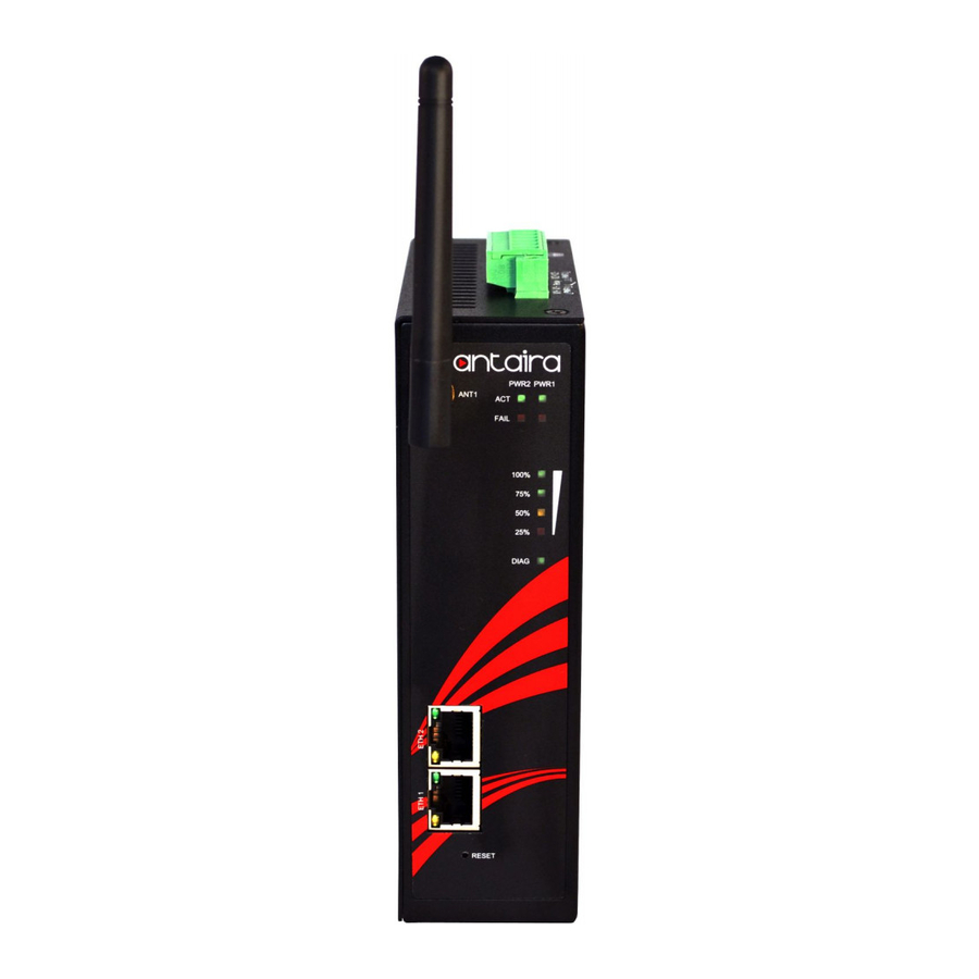
Hardware Overview Front Panel The following table describes the labels on the APN-210N Port Description 10/100 RJ-45 fast 2 10/100Base-T(X) RJ-45 fast Ethernet ports support Ethernet ports auto-negotiation Default Setting : Speed: auto ANT 1 Reversed SMA connector for external antenna... -
Page 12: Front Panel Leds
ETH 2 Green Port link up at 100Mbps Top Panel The top panel components of the APN-210N are showed as below: *Terminal block includes: PWR1, PWR2 (12 ~ 24V DC) and Relay output (1A@24VDC) Relay Output Ground (1A @ 24VDC) -
Page 13: Rear Panel
Rear Panel The rear panel components of the APN-210N are showed as below: Screw holes for wall mount kit. DIN-Rail kit Rare panel of the APN-210N... -
Page 14: Cables And Antennas
Cables and Antennas Ethernet Cables The APN-210N WLAN AP has standard Ethernet ports. According to the link type, the AP use CAT 3, 4, 5,5e UTP cables to connect to any other network device (PCs, servers, switches, routers, or hubs). Please refer to the following table for cable specifications. -
Page 15: Wireless Antenna
Note: “+” and “-” signs represent the polarity of the wires that make up each wire pair. Wireless Antenna 2.4GHz antennas are used for the APN-210N and connected with reversed SMA connectors. External antennas also can be applied with this connectors. -
Page 16: Operation Modes & Connection Examples
Operation Modes & Connection Examples Access Point and Access Point WDS Mode The Access Point Mode is the default mode of the device. It enables the bridging of wireless clients to wired network infrastructure and enables transparent access and communication with each other. The illustration below shows a typical resources sharing application example using this device. -
Page 17: Station Mode
Station Mode In Station mode the device acts as a wireless client. When connected to an access point, it creates a network link between the Ethernet network connected at this client device, and the wireless Ethernet network connected at the access point. In this example the workgroup PCs on the ethernet network connected to the Station device can access the printer across the wireless connection to the access point where the printer is connected. -
Page 18: Station Wds Mode
Station WDS Mode Station WDS mode is similar to Station mode. The difference is Station WDS must connect to access point configured to Access Point WDS (or RootAP) mode. Station WDS is mainly use for point-to–point connection between 2 buildings or locations as far as several kilometer away. -
Page 19: Repeater Wds Mode
Repeater WDS Mode Repeater WDS Mode to mainly to extend the wireless range and coverage of the wireless network allowing access and communications over places generally difficult for wireless clients to connect to the network. In Repeater mode, the access point acts as a relay for network signals on the network by regenerating the signals it receives, and retransmitting them to main network infrastructure. -
Page 20: For Windows 95/98/98Se/Me/Nt
For Windows 95/98/98SE/ME/NT From your desktop, right-click the Network Neighborhood icon and select Properties. Select the network adapter that you are using, then right-click and select Properties. Highlight TCP/IP and click on the Properties button. Select the Specify an IP address radio button. -
Page 21: For Windows Xp/2000
been correctly assigned to your PC, go to the Start menu, select Run, and enter the command: winipcfg. Select the Ethernet adapter from the drop-down list and click OK. PC is now setup with a proper IP address to communicate with the access point. For Windows XP/2000 Go to your desktop, right-click on the My Network Places icon and select Properties. - Page 22 Select the Use the following IP address radio button. Set the IP address to 192.168.168.X and subnet mask to 255.255.255.0, where X can be any number from 2 to 254. Click on the OK button to close all windows. To verify that the IP address has been correctly assigned to your PC, go to the Start menu, Accessories, select Command Prompt, and type the command: ipconfig/all PC is now setup with a proper IP address to communicate with the access point.
-
Page 23: Access The Web Interface
Access the Web Interface Access with uConfig The UConfig utility provides direct access to the web interface. Click icon to launch the utility then click button. - Page 24 Select the access point from the products list and click on the button. To retrieve and display the latest device(s) in the list, click on the button. Do not exit the uConfig program while accessing the web-based interface as this will disconnect you from the device.
- Page 25 At the login prompt, enter the User Name and Password. The default are : User Name : admin Password : password It then opens the device home page. The Status page.
-
Page 26: Access With Web Browser
Access with Web Browser Launch your Web browser, e.g. Internet Explorer, FireFox, Netscape, etc. If using MS IE, under the tab, select Open the tab and in the section disable all the option boxes. Click on the button to update the changes. At the bar type in http://192.168.168.1 and press on your keyboard. - Page 27 At the login prompt, enter the User Name and Password. The default are : User Name : admin Password : password It then opens the device home page. The Status page.
-
Page 29: Navigation
Navigation Main Menu Bar Status: Page displays current status of the device and the statistical information. Basic Wireless: Page contains the controls for a wireless network configuration, while covering basic wireless settings which define operating mode, associating details and data security options. Basic Network: Page covers the configuration of network operating mode, IP settings and network services (i.e. -
Page 30: Basic Network Tab
Basic Network Tab Click BASIC NETWORK from the menu bar to open the page as show below. Network Mode: Bridging Network Mode: Bridge mode (default) LAN Setup LAN Mode: Static: (default) lets you enter a specific IP address for the device. Default IP address is 192.168.168.1 DHCP Client: when set let device learn the IP address automatically from the network. - Page 31 Gateway: (optional) Enter the gateway IP address of the network the device is connected. Primary DNS IP : (optional) Enter the primary DNS IP address nearest to the gateway router. Secondary DNS IP: (optional) Enter the secondary DNS IP address nearest to the gateway router. DHCP Mode: None: function disabled DHCP Server: Check to enable.
- Page 32 DHCP Reservations Click Add to enter for each device the IP address and MAC address. All DHCP active lease devices are displayed in the Status tab page from the More Status selection. Domain Name Server Entry The Primary and Secondary DNS IP addresses entry is for device operation to resolve domain name to reach certain servers like internet time server and other services that use domain name.
-
Page 33: Basic Wireless Tab
Basic Wireless Tab Under the tab, there is the selection of 4 radios. Fig 2.1 Basic Wireless Tab Currently device support only one 802.11n radio card. Select RADIO 1 to configure. Basic Wireless Tab contains all the wireless setup, which is necessary for the operator to setup the wireless part of the link. -
Page 34: Access Point Parameters Settings
allows a client or station device to bridge wireless traffic transparently. Station: This is a client mode that can be connected to the Access Point mode. It is used to bridge the wireless connection to an Access Point. It forwards all the traffic to/from the network devices to the Ethernet interface. - Page 35 be specified while operating in Access Point or Access Point WDS mode. All the client devices within its range will receive broadcast messages from the access point advertising this SSID. Hide SSID: Once checked, this will disable advertising the SSID of the access point in broadcast messages to wireless stations.
-
Page 36: Station Parameters Settings
condition the amount of errors at the data rate and fine tune to the best data rate it can use. Transmit Power The maximum transmit power displayed is determined by the country code and the maximum transmit power of the miniPCI that is being used. *Note on changing channels: When the operator changes the channels and if this new frequency have higher power output permitted by regulation, the power previously selected low power level will... - Page 37 Remote AP-ESSID This is the Service Set Identifier used by station to seek and connect to the access point of same the SSID identifier. Site Survey Site Survey will search for the available wireless networks in range on all the supported channels and will allow you to select one for association.
-
Page 38: Wireless Security
20MHz will to help reduce interference on the link and improve performance. * Note: 40MHz bandwidth is non-standard for 802.11n/g mode operation. If you experience unstable performance change Channel Spectrum Width to 20M. ** Station setting must match AP Channel Spectrum Width setting. Maximum : checking this box will result in maximum Tx output power overriding regulation. - Page 39 WPA PSK PSK (Default) – WPA or WPA2 with Pre-shared Key method. Cipher Type TKIP - Temporal Key Integrity Protocol which uses RC4 encryption algorithm. AES - Advanced Encryption Standard (AES) algorithm. AUTO (Default) – Automatically select between both algorithms. Preshared Key This option is available when WPA or WPA2, with PSK selected.
- Page 40 Secondary Radius Server IP Enter the Secondary Radius Server IP address. Authentication Port Enter the Authentication Port number of the Radius Server. Default is 1812. Accounting Port Enter the Accounting Port number of the Radius Server. Default is 1813. Radius Secret Key Enter the Secret Key of the Radius Server.
- Page 41 IEEE802.1x Settings The operation of the Keys is the same for ALL the modes. ** Note: Operating with IEEE802.1x security will limit AP to maximum wireless link speed of 54Mbps only. Fig. 2.8 IEEE802.1X (Access Point/Access Point WDS/ Repeater WDS) This option apply to the following modes only, when WPA EAP or IEEE802.1x .
- Page 42 IEEE802.1x Key Length This is the key length of the initial seed key. Select 64 or 128bit. Fig 2.6 WEP The operation of the Keys is the same for ALL the modes. ** Note: Operating with WEP security will limit AP to maximum wireless link speed of 54Mbps only.
-
Page 43: Virtual Access Point (Vap)
Virtual Access Point (VAP) Virtual AP (VAP) implements mSSID (Multi-SSID) whereby a single wireless card can be setup with up to 3 virtual SSID of BSSID connections. Each VAP can be set with different security authentication mode. Fig 2.11 Virtual AP (Only Available in Access Point/ Access Point WDS Mode) All VAPs are created from the same radio they all share the same wireless channel, country code, channel spectrum width and transmit power. -
Page 44: Advance Wireless Tab
Advance Wireless Tab Click Advanced Wireless tab from menu and select RADIO 1 to open the page below. Long Range Parameters Setup Advanced wireless page let you setup outdoor long distant connection parameters. Long Range Parameters: Check to enable parameters. Beacon Interval: (default is 100 ms) Define the time interval (in millisecond) the beacon to broadcast. - Page 45 Noise Immunity: Check to enable. When enabled, it automatically adjusts the signal/noise level for best performance. In low noise environment it is recommended to turn off this function. Signal Strength Indicator (RSSI): The default values are LED1-Red (10), LED2-Yellow (20), LED3-Green (40) Each LEDs when turn on indicates the RSSI signal strength has hit over the value.
-
Page 46: Services Tab
Services Tab Click Services tab from menu to open the page below. Services section provides varieties of useful and enhanced functions to help assist device operations. -
Page 47: Ping Watchdog
Ping Watchdog Enable Ping Watchdog: Default is disabled. Check on box to enable. IP Address To Ping: Target IP address do ping test monitor. Ping Interval: Default is 5 seconds (minimum). This is Ping test duration. Startup Delay: Default is 60 seconds(minimum). One time delay after device startup. -
Page 48: Snmp Setup
SNMP Setup Enable SNMP: Default is disabled. Check on box to enable. Read Only Password: Password to query device. Engine ID: Default is 800007e5BD00002704D000007c Enable SNMP Trap: Default is disabled. Check on box to enable. Trap Destination IP: Enter the IP to send the info when trap is triggered. Community: Enter the SNMP community string. -
Page 49: Telnet Access Setup
Telnet Access Setup Enable Telnet Server: Default is enabled. Remove check on box to disable. Server Port: Default is 23. Enter new preferred port number. SSH Access Setup Enable SSH Server: Default is disabled. Check on box to enable. Server Port: Default is 22. -
Page 50: System Tab
System Tab The System Page contains Administrative options. This page enables administrator to customize, reboot the device, set it to factory defaults, upload a new firmware, backup or update the configuration and configure administrator’s credentials. Firmware Upgrade Use this section to find out current software version and update the device with the new firmware. -
Page 51: Host Name
Host Name Host Name is the system wide device identifier. It is reported by SNMP Agent to authorized management stations. Host Name will be represented in popular Router Operating Systems registration screens and discovery tools. Host Name: specifies the system identity. Change button saves the Host Name if activated. -
Page 52: Configuration Management
Enable Read-Only Account Read-Only Username Password: new password used for read-only administrator authentication should be specified. Configuration Management Backup Configuration: click Download button to export the current configuration to a file. Upload Configuration: click Browse button to navigate to and select the new configuration file or specify the full path to the configuration file location. - Page 53 to factory defaults routine. Reset routine initiates system Reboot process (similar to the power off - power on cycle). The running system configuration will be deleted and the default system configuration (all the system settings with no exception) will be set. After the Reset to Defaults routine is completed, the device system will return to the default IP configuration (192.168.168.1/255.255.255.0) and will start operating in Station-Bridge mode.
-
Page 54: Status Page
Status Page The Status Page displays a summary of link status information, current values of basic configuration settings (depending on operating mode), network settings and traffic statistics of all the interfaces. Status Reporting Main Uptime: displays device up time since boot up. The time is expressed in days, hours, minutes and seconds. -
Page 55: Lan Setting
LAN Pri. DNS IP: displays the Primary DNS IP address of the LAN setting. LAN Sec. DNS IP: displays the Secondary DNS IP address of the LAN setting. WAN Setting Not available in APN-210N units Radio Wireless Mode: displays the current operating mode of the device. -
Page 56: Station Connection Info
Clients Connection Status in AP Status Info All clients connected to AP can be view from AP Status page. Below is an example of a client’s connection status info. Click to refresh client connection statistics and status page Signals strength at the left and right port of radio card can be view with more accurately while adjusting the antenna to get a more balanced reception. - Page 57 WLAN Connected Status: MAC Address: displays the MAC address of the current active WLAN card. Signal Strength: displays the received wireless signal level of opposite connected device. TX Rate and RX Rate: displays the current 802.11 data transmission (TX) and data reception (RX) rate while operating in Station mode.
-
Page 58: More Status
More Status In More Status option contains some useful tools and additional status pages. Ping Utility – a ping tool to test the connectivity between devices. ARP Table display a list of MAC addresses of the connected devices Bridge Table display a list the devices connect to the bridge interface DHCP Active Lease Table display a list of IPs addresses leased to all computers. -
Page 59: Vlan Tab
VLAN Tab This setup lets you create virtual local network connection through the device Ethernet only and over wireless connections. By default VLAN mode is disabled and checked on No VLAN VLAN Switch To setup VLAN network check on VLAN Switch To add a Tag VLAN ID for Ethernet port, type in the ID number select Tag and click Add To add a Tag VLAN ID for MAIN wireless SSID, type in the ID number select Tag and click Add To add a Tag VLAN ID for VAP1 wireless SSID, type in the ID number select Tag and click Add... -
Page 60: Vlan Management
VLAN Management VLAN management lets you control and limit only clients connection of same tag VLAN ID group be open AP device web page. * Note:- VLAN Management works only in tag VLAN pass-through mode. i.e. VLAN Switch is disabled. When VLAN Switch is enabled or configured, VLAN Management function stops operation. -
Page 61: Appendix I - Network
Appendix I - Network This section provides more detailed explanation on the network operation modes in general. The Network Page allows the administrator to setup bridge or routing functionality. Device can operate in bridge or router mode. The IP configuration as described below is required for device management purposes. - Page 62 segment where device resides. If the device IP settings and administrator PC (which is connected to the device in wired or wireless way) IP settings will use different address space, the device will become unreachable. Netmask: This is a value which when expanded into binary provides a mapping to define which portions of IP address groups can be classified as host devices and network devices.
- Page 63 it is the IP of the host system which sends the packets; Source Port is the source port of the TCP/UDP packet (specified within the packet header), usually it is the port of the host system application which sends the packets; Destination IP/mask is the destination IP of the packet (specified within the packet header), usually it is the IP of the system which the packet is addressed to;...
-
Page 64: Appendix Ii- Advanced Settings
Appendix II- Advanced Settings This section provides more detail explanation on advanced setting for routing and wireless settings. The Advanced options page allows you to manage advanced settings that influence on the device performance and behavior. The advanced wireless settings are dedicated for more technically advanced users who have a sufficient knowledge about wireless LAN technology. - Page 65 during which all the other stations hold off the transmission and wait until the requesting station will finish transmission. Fragmentation Threshold: specifies the maximum size for a packet before data is fragmented into multiple packets. The range is 256-2346 bytes, or word “off”. Setting the Fragmentation Threshold too low may result in poor network performance.
- Page 66 Signal Strength LED Settings LED Thresholds Configuration The LED's for signal strength on the device can be made to light on when received signal levels reach the values defined in the following fields. This allows a technician to easily deploy a CPE without logging into the unit (i.e. for antenna alignment operation). Signal LED Thresholds specify the marginal value of Signal Strength (dBm) which will switch on LEDs indicating signal strength: LED 1 (Red) will switch on if the Signal Strength reaches the value set in...
-
Page 67: Appendix Iii- Services
Appendix III- Services This section provides more details on the system management services. Ping WatchDog The ping watchdog sets the device to continuously ping a user defined IP address (it can be the internet gateway for example). If it is unable to ping under the user defined constraints, the device will automatically reboot. - Page 68 Contact: specify the identity or contact in case an emergency situation arise. Location: specify the physical location of the device. NTP Client, Web, Telnet, SSH Server NTP Client: The Network Time Protocol (NTP) is a protocol for synchronizing the clocks of computer systems over packet-switched, variable-latency data networks.
-
Page 69: Appendix Iv- Vlan Setup Examples
Appendix IV- VLAN Setup examples A) Tagged Wireless VLAN to Tagged Ethernet VLAN Setup... -
Page 70: B) Untagged Wireless Vlan To Tagged Ethernet Vlan Setup
B) Untagged Wireless VLAN to Tagged Ethernet VLAN setup C) Tagged VLAN Pass-Through AP and Station link No VLAN Setup Required...
Need help?
Do you have a question about the APN-210N and is the answer not in the manual?
Questions and answers