Table of Contents
Advertisement
Quick Links
Advertisement
Table of Contents

Related Manuals for ANTAIRA APX-3200


Summary of Contents for ANTAIRA APX-3200
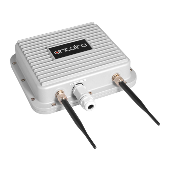
- Page 1 APX-3200 Industrial Wireless-N Access Point User Manual Version 1.1...
- Page 2 Trademark Information Antaira is a registered trademark of Antaira Technologies, LLC, Microsoft Windows and the Windows logo are the trademarks of Microsoft Corp. NetWare is the registered trademark of Novell Inc. WMM and WPA are the registered trademarks of Wi-Fi Alliance.
- Page 3 Industrial Wireless N-Access Point User Manual Version 1.1 July 2014 This manual supports the following model: APX-3200 This document is the current official release manual. Please check our website (www.antaira.com) for any updated manual or contact us by e-mail (support@antaira.com).
-
Page 4: Table Of Contents
Table of Contents Overview ......................6 Introduction ....................6 Features and Benefits ......................... 7 Hardware Installation ..................8 Pole Mounting Installation ................8 Wall Mount Installation ........................ 8 Hardware Overview..................9 Front Panel ............................ 9 Cables and Antennas .................. 10 Ethernet Cables .......................... - Page 5 Services Tab ....................41 Ping Watchdog ........................... 42 Auto-Reboot ..........................42 SNMP Setup ..........................43 NTP Setup ........................... 43 Web HTTP Security ........................43 Telnet Access Setup ........................44 SSH Access Setup ........................44 System Log Setup ........................44 DDNS ............................44 System Tab ....................
-
Page 6: Overview
Overview Introduction The high-performance wireless network Access Point (AP) is designed for industrial and enterprise access applications. Embedded with the Atheros chipset, it boasts network robustness, stability and wider network coverage. Based on 802.11n (Draft 2.0), the access point supports high-speed data transmission of up to 300Mbps. -
Page 7: Features And Benefits
Features and Benefits Point-to-Point & Point-to-Multipoint Support Point-to-point and point-to-multipoint communication between different buildings enable users to bridge wireless clients that are kilometers apart while unifying the networks. Virtual AP (Multiple SSID) Virtual AP implements mSSID (Multi-SSID) allows a single wireless system to be set up with multiple virtual AP connections with different SSIDs or BSSID (Basic Service Set Identifier) and different security settings. -
Page 8: Hardware Installation
Hardware Installation Pole Mounting Installation Each AP has a pole mounting kit on the rear panel. The pole mounting kit helps to fix the AP in the appropriate location. Wall Mount Installation Each AP has another installation method to fix the AP. A wall mount panel can be found in the package. The following step shows how to mount the AP on the wall. -
Page 9: Hardware Overview
Hardware Overview Front Panel The following table describes the connectors on the APX-3200. Port Description 1*10/100 Base-T(X) RJ-45 fast Ethernet port supports IEEE 10/100 RJ-45 Fast Ethernet Ports 802.3af PoE (powered device) Default Speed: Auto ANT (1/2) N-type connector for external antenna... -
Page 10: Cables And Antennas
Cables and Antennas Ethernet Cables The APX-3200 WLAN AP has a PoE Ethernet port. According to the link type, the AP use CAT 3, 4, 5,5e UTP cables to connect to any other network device (PCs, servers, switches, routers, or hubs). -
Page 11: Wireless Antenna
The APX-3200 supports auto MDI/MDI-X operation. You can use a straight-through cable to connect PC and AP. The following table below shows the 10BASE-T/ 100BASE-TX MDI and MDI-X port pin outs. MDI/MDI-X Pin Assignments Pin Number MDI port MDI-X port... -
Page 12: Operation Modes & Connection Examples
Operation Modes & Connection Examples Access Point and Access Point WDS Mode The access point mode is the default mode for the device. It enables the bridging of wireless clients to wired network infrastructures and enables transparent access and communication with each other. -
Page 13: Station Mode
Station Mode In station mode the device acts as a wireless client. When connected to an access point, it creates a network link between the Ethernet network connected at the client device and the wireless Ethernet network connected at the access point. In the example below, the workgroup of PCs on the Ethernet network are connected to the station device, which can access the printer across the wireless connection to the access point where the printer is connected. -
Page 14: Station Wds Mode
Station WDS Mode Station WDS mode is similar to station mode. The difference is that station WDS mode must connect to an AP that is configured in access point WDS (or RootAP) mode. station WDS is mainly used for a point-to–point connection between two buildings or locations that are further away. -
Page 15: Repeater Wds Mode
Repeater WDS Mode Repeater WDS Mode is mainly used to extend the wireless range and coverage of the wireless network allowing access and communication to go over places which are generally difficult for wireless clients to connect to a network. In repeater mode, the AP acts as a relay for network signals on the network by regenerating the signals it receives, and retransmitting them to the main network infrastructure. -
Page 16: Configure The Ip Address
Configure the IP Address After setting up the hardware, the user needs to assign an IP address to the PC so that it is in the same subnet as the access point. For Windows 95/98/98SE/ME/NT From your desktop, right-click the Network Neighborhood icon and select Properties. Select the network adapter that you are using, then right-click and select Properties. -
Page 17: For Windows Xp/2000
To verify that the IP address has been correctly assigned to your PC, go to the Start menu, select Run, and enter the command: winipcfg. Select the Ethernet adapter from the drop-down list and click OK. PC is now setup with a proper IP address to communicate with the access point. For Windows XP/2000 Go to your desktop, right-click on the My Network Places icon and select Properties. - Page 18 Right-click the network adapter icon and select Properties. Highlight Internet Protocol (TCP/IP) and click on the Properties button. Select the Use the following IP address radio button. Set the IP address to 192.168.168.X and subnet mask to 255.255.255.0, where X can be any number from 2 to 254.
- Page 19 To verify that the IP address has been correctly assigned to your PC, go to the Start menu, Accessories, select Command Prompt, and type the command: ipconfig/all PC is now setup with a proper IP address to communicate with the access point.
-
Page 20: Access The Web Interface
Access the Web Interface Access with uConfig The uConfig utility provides direct access to the web interface. Click icon to launch the utility then click button. Select the access point from the products list and click on the button. To retrieve and display the latest device(s) in the list, click on the button. - Page 21 Do not exit the uConfig program while accessing the web-based interface as this will disconnect you from the device. Click on the button.
- Page 22 At the login prompt, enter the User Name and Password. The default are : User Name : admin Password : password It then opens the device’s home page-the ‘Status’ page.
-
Page 23: Access With Web Browser
Access with Web Browser Launch your web browser, e.g. Internet Explorer, FireFox, Netscape, etc. If using MS IE, under the tab, select Open the tab and in the section disable all the option boxes. Click on the button to update the changes. At the bar type in http://192.168.168.1 and press on your keyboard. - Page 24 At the login prompt, enter the User Name and Password. The default are : User Name : admin Password : password It then opens the device’s home page-the ‘Status’ page.
-
Page 25: Navigation
Navigation Main Menu Bar Status: Page displays current status of the device and the statistical information. Basic Wireless: Page contains the controls for a wireless network configuration, while covering basic wireless settings which define operating mode, associating details and data security options. -
Page 26: Basic Network Tab
Basic Network Tab Click BASIC NETWORK from the menu bar to open the page shown below. Network Mode: Bridging Network Mode: Bridge (default) mode. LAN Setup LAN Mode: Static: (Default) This allows the user to enter a specific IP address for the device. Default IP address is 192.168.168.1 ... - Page 27 Gateway: (Optional) Enter the gateway IP address of the network for the connected device. Primary DNS IP : (Optional) Enter the primary DNS IP address nearest the gateway router. Secondary DNS IP: (Optional) Enter the secondary DNS IP address nearest the gateway router.
-
Page 28: Basic Wireless Tab
Domain Name Server Entry The primary and secondary DNS IP address entry is for the device operation to resolve the domain name in order to reach certain servers like the internet time server among other services that use the domain name. * Note: Ensure the device gateway IP is also set to allow devices to access the internet. -
Page 29: Enable The Radio
Enable the Radio Fig 2.2 Enable Radio Checkbox Click or un-click the checkbox to enable or disable the radio. Basic Wireless Settings All the basic wireless settings can be configured using the information on this page. Operators can change the ESSID, regulatory country code, wireless profile, channel spectrum width, frequency of interest, data rates, transmit power and rate aggressiveness. -
Page 30: Access Point Parameter Settings
mode, it is fully transparent at the layer 2 level. **Note: For Station WDS, Access Point WDS, Repeater WDS: WDS protocol used is not defined as the standard, thus compatibility issues between equipment from different vendors might arise. Repeater WDS: This mode consists of a station WDS and an access point WDS mode. - Page 31 channel-spectrum width modes will be tuned accordingly to the regulations of the selected country. No Country Set: Option when checked; only the frequency range is available. 11n 2.4GHz is 2412-2462MHz. Wireless Profile: The NG is 11n 2.4GHz band and represents a mix of 802.11n, 802.11g and 802.11b mod e.
-
Page 32: Station Parameters Settings
Rate Aggressiveness This allows users to reduce or increase the transmit rate while still remaining in full auto algorithm. There are two scenarios when rate aggressiveness is useful. First, the environment might be noisy at times, so one would lower the throughput to ensure better stability, and the rate aggressiveness allows the device to reduce the transmit rate, so the range or power can be higher. - Page 33 ote AP – Lock to MAC Enter the MAC address of the remote access point the device is connected to. This option will only make the device connect to this access point. It is important when the connection is point-to-point operation. ...
-
Page 34: Wireless Security
Wireless Security All the wireless security settings are featured in this section. The operation of the keys is the same for ALL the wireless modes. WPA or WPA2 Authentication Fig 2.7 WPA (Access Point/Access Point WDS/Repeater WDS) PSK (Default) – WPA or WPA2 with a pre-shared key method. WPA PSK: Cipher Type ... - Page 35 WPA + EAP Fig 2.8 WPA + EAP EAP – WPA or WPA2 with EAP (Extensible Authentication Protocol) Firmware supported options for clients are: EAP-TTLS and EAP-PEAP. Cipher Type TKIP - Temporal Key Integrity Protocol which uses an RC4 encryption algorithm. ...
- Page 36 Station, Station WDS, Repeater WDS Mode Identity: Identification credential used by the WPA-supplicant for EAP authentication. User Name: Identification credential used by the WPA-supplicant for EAP tunneled authentication in an unencrypted form. User Password: The password credential used by the WPA-supplicant for the EAP authentication.
- Page 37 Access Point, Access Point WDS, Repeater WDS Modes Primary Radius Server IP: Enter the primary radius server IP that the access point will use to query the server. Secondary Radius Server IP: Enter the secondary radius server IP that the access point will use to query the server.
-
Page 38: Virtual Access Point (Vap)
Authentication Type: Open Authentication – (Default) No authentication. It is recommend to use this standard option over the shared authentication. Shared Authentication – May not be compatible with all the access points, and it is not recommended. Key Type: HEX or ASCII option specifies the character format for the WEP key if WEP security method is used. -
Page 39: Advance Wireless Tab
Advance Wireless Tab Click the Advanced Wireless tab from the menu and select RADIO 1 to open the page below Long Range Parameters Setup The advanced wireless page will allow the user to setup outdoor long distant connection parameters. Long Range Parameters: Check to enable parameters. - Page 40 calculated. Fine tuning can be further adjusted, especially in consideration of the environmental conditions which can help to achieve the best performance and better link reliability. Noise Immunity: Check the box to enable this setting. When enabled, it automatically adjusts the signal/noise level for the best performance.
-
Page 41: Services Tab
Services Tab Click the Services tab from menu to open the page below. The services section provides a variety of useful and enhanced functions to help assist device operations. -
Page 42: Ping Watchdog
Ping Watchdog Enable Ping Watchdog: Default is disabled. Check on box to enable. IP Address to Ping: Target IP address to ping test monitor. Ping Interval: Default is 5 seconds (minimum). This is the ping test duration. Startup Delay: Default is 60 seconds (minimum). -
Page 43: Snmp Setup
SNMP Setup Enable SNMP: Default is disabled. Check on box to enable. Read Only Password: Password to query device. Engine ID: Default is 800007e5BD00002704D000007c. Enable SNMP Trap: Default is disabled. Check on box to enable. Trap Destination IP: Enter the IP to send the info when trap is triggered. Community: Enter the SNMP community string. -
Page 44: Telnet Access Setup
Telnet Access Setup Enable Telnet Server: Default is enabled. Remove check on box to disable. Server Port: Default is 23. Enter new preferred port number. SSH Access Setup Enable SSH Server: Default is disabled. Check on box to enable. Server Port: Default is 22. -
Page 45: System Tab
System Tab The system page contains administrative options. This page enables the administrator to customize, reboot the device, set it to factory defaults, upload a new firmware, backup or update the configuration and configure administrator’s credentials. Firmware Upgrade Use this section to find the current software version and update for the device with the latest firmware. -
Page 46: Host Name
Host Name Host Name is the system wide device identifier. It is reported by the SNMP agent to authorized management stations. The host name will be represented in the popular router operating systems registration screen and discovery tools. Host Name: specifies the system identity. Change button saves the host name if activated. -
Page 47: Configuration Management
Enable Read-Only Account Username: Read-Only Password: A new password will be used for the read-only administrator authentication and should be specified. Configuration Management Backup Configuration: Click the ‘Download’ button to export the current configuration to a file. Upload Configuration: Click the ‘Browse’ button to navigate to and select the new configuration file or specify the full path to the configuration file location. - Page 48 device to the factory default routine. The reset routine initiates the system reboot process (similar to the power off - power on cycle). The running system configuration will be deleted and the default system configuration (all the system settings with no exception) will be set. After the Reset to Defaults routine is completed, the device will return to the default IP configuration (192.168.168.1/255.255.255.0) and will start operating in station-bridge mode.
-
Page 49: Status Page
Status Page The status page displays a summary of the link status information, current values of basic configuration settings (depending on operating mode), network settings and traffic statistics of all the interfaces. Status Reporting Main Uptime: Displays the device’s up time since boot up. The time is expressed in days, hours, minutes and seconds. -
Page 50: Client Connection Status In Ap Status Info
LAN Gateway IP Address: Displays the IP address of the gateway used in LAN. LAN Pri. DNS IP: Displays the primary DNS IP address of the LAN setting. LAN Sec. DNS IP: Displays the secondary DNS IP address of the LAN setting. WAN Setting ... - Page 51 Signal strength at the left and right port of the radio card can be viewed more accurately while adjusting the antenna to get a more balanced reception.
-
Page 52: Station Connection Info
Station Connection Info Status Info Click to refresh client connection statistics and status page. WLAN Connected Status: MAC Address: Displays the MAC address of the current active WLAN card. Signal Strength: Displays the received wireless signal level of the opposite connected device. - Page 53 were encrypted with the wrong encryption key and failed the decryption routines. It can be used to detect invalid wireless security settings and encryption break attempts. Rx Invalid Frag value represents the number of packets missed during transmission and reception.
-
Page 54: More Status
More Status The ‘More Status’ option contains useful tools specifically for the status pages. Ping Utility – Use the ping tool to test the connectivity between devices. ARP Table displays a list of MAC addresses of the connected devices. Bridge Table displays a list of devices connected to a bridge interface. DHCP Active Lease Table displays a list of IP addresses leased to all computers. -
Page 55: Vlan Tab
VLAN Tab This setup allows the user to create a virtual local network connection through the device’s Ethernet and wireless connection. By default, the VLAN mode is disabled and checked on No VLAN. VLAN Switch To setup a VLAN network, click the circle next to VLAN Switch. ... -
Page 56: Vlan Management
VLAN Management VLAN management allows the user to control and limit clients’ connections to the same tag VLAN ID group. * Note: VLAN Management works only in the tag VLAN pass-through mode. i.e. VLAN Switch is disabled. When VLAN Switch is enabled or configured, the VLAN Management function stops operating. -
Page 57: Appendix I - Network
Appendix I - Network This section provides a more general and detailed explanation on the network operation modes. The ‘Network Page’ allows the administrator to setup up the bridge or routing functionality. The device can operate in bridge mode. The IP configuration as described below is required for device management purposes. - Page 58 Netmask: A value when expanded into binary that provides a mapping to define which portions of the IP address groups can be classified as host devices and network devices. Netmask defines the address space of the network segment where the device resides. 255.255.255.0 (or /24) Netmask is commonly used among many C Class IP networks.
- Page 59 to the internal network. The specified port will be accessible from the external network. Type is the Layer 3 protocol (IP) type which needs to be forwarded from the internal network. Public Port is the TCP/UDP port of the based device which will accept and forward the connections from the external network to the host connected to the internal network.
- Page 60 DMZ IP: This is connected to the internal network host, specified with the DMZ IP address which will be accessible from the external network. With a multicast design, applications can send one copy of each packet and address it to a group of computers that want to receive it. This technique addresses packets to a group of receivers rather than to a single receiver.
-
Page 61: Appendix Ii- Advanced Settings
Appendix II- Advanced Settings This section provides a more detail explanation on advanced settings for routing and wireless settings. The advanced options page allows the user to manage advanced settings that influence the device’s performance and behavior. The advanced wireless settings are dedicated toward a more technically advanced user who has a sufficient knowledge about wireless LAN technology. - Page 62 station has finished the transmission. Fragmentation Threshold: This specifies the maximum size for a packet before data is fragmented into multiple packets. The range is 256-2346 bytes, or word “off”. Setting the fragmentation threshold too low may result in poor network performance. The use of fragmentation can increase the reliability of frame transmissions.
-
Page 63: Appendix Iii- Services
Appendix III- Services This section provides more details on the system management services. Ping WatchDog The ping watchdog sets the device to continuously ping a user’s defined IP address (it can be the internet gateway for example). If it is unable to ping under the user defined constraints, the device will automatically reboot. - Page 64 NTP Client, Web, Telnet, SSH Server NTP Client: The Network Time Protocol (NTP) is a protocol for synchronizing the clocks of the computer systems over packet-switched and variable-latency data networks. If the option log is enabled, it can be used to set the device’s system time which is reported next to every system log entry while registering system events.
-
Page 65: Appendix Iv- Vlan Setup Examples
Appendix IV- VLAN Setup examples A) Tagged Wireless VLAN to Tagged Ethernet VLAN Setup... -
Page 66: B) Untagged Wireless Vlan To Tagged Ethernet Vlan Setup
Antaira Customer Service and Support (Antaira US Headquarter) + 844-268-2472 (Antaira Europe Office) + 48-22-862-88-81 (Antaira Asia Office) + 886-2-2218-9733 Please report any problems to Antaira: www.antaira.com support@antaira.com www.antaira.eu info@antaira.eu www.antaira.com.tw info@antaira.com.tw Any changes to this material will be announced on the Antaira website.
Need help?
Do you have a question about the APX-3200 and is the answer not in the manual?
Questions and answers