Invacare Mirage Service Manual
Hide thumbs
Also See for Mirage:
- Operating manual (121 pages) ,
- User manual (116 pages) ,
- Service manual (32 pages)
Table of Contents
Advertisement
Quick Links
Advertisement
Table of Contents

Related Manuals for Invacare Mirage


Summary of Contents for Invacare Mirage
- Page 1 Invacare® Mirage Service manual...
- Page 2 Introduction This manual provides basic details to enable the Invacare® MIRAGE Wheelchair • to be maintained. It is not intended to be a comprehensive maintenance guide/policy, but is intended for use by competent personnel to enable the chair to be adequately maintained.
-
Page 3: Notes On Transport
Information about operation or about general maintenance and care work should • be taken from the wheelchair Operating Manual. Failure to comply with the above absolves INVACARE Ltd of liability. Note: Certain components will require removal to carry out maintenance. With the exception of fasteners, those components should be refitted. -
Page 4: Table Of Contents
Contents Layout of Modules components and controls Safety and assembly instructions Before any inspection or repair work..................6 During dismantling/reassembly ....................6 Before operation / after completion of work:................6 Tools Required Armrests Tools Required: .........................9 Inspection:..........................9 Disassembly / Assembly......................9 Legrests Tools Required: ........................11 Inspection:..........................11 Disassembly / Assembly......................11 Upholstery Seat and Back... - Page 5 12.5 Power Module Connector Orientation...................24 12.6 Schematic Diagram .........................25 13 Batteries and Charger 13.1 Tools Required ........................26 13.2 Inspection..........................26 13.3 Disassembly..........................27 13.4 Assembly..........................27 13.5 Inspection – Battery Charger ....................27 13.6 Battery Wiring Diagram......................28 14 Mechanical Brakes 14.1 Tools Required ........................28 14.2 Inspection..........................28 14.3...
-
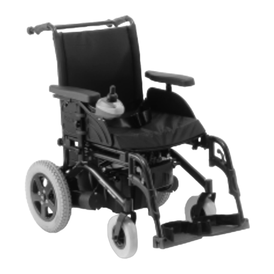
Page 6: Layout Of Modules Components And Controls
1 Layout of Modules components and controls Main Frame Motor Gearbox Front Castor Wheel Rear Drive Wheel Legrest Seat Backrest Armrest Footplate Shark Remote Shark Power Module Battery Boxes Back Brace Anti Tipper Wheels Mechanical Brakes Batteries (Removed) Legrests (Removed) Armrests (Removed) Backrest (removed) Folded Chassis... -
Page 7: Safety And Assembly Instructions
2 Safety and assembly instructions These safety instructions are intended to prevent accidents at work and it is imperative that they are observed. 2.1 Before any inspection or repair work Read and observe this repair manual and the associated operating manual. Caution: Please note the heavy weight of some components. -
Page 8: Tools Required
3 Tools Required The following list gives the basic tools required to perform the maintenance procedures as illustrated in this manual. 1 –Open Ended Spanner (7mm) • 2 - Open End Spanner (8mm) • 2 - Open End Spanner (10mm) •... -
Page 9: Armrests
4 Armrests Armrest Top – Parts Armpad Armrest top assembly Armpad screws Hand wheel Armrest Lower – Parts Skirt Guard Armrest Lower Tube Screws Skirt Guard Clamps Hand wheel Fixing Hand wheel Armrest Socket... -
Page 10: Tools Required
4.1 Tools Required: 1. No 2 Cross Point Screwdriver 2. Flat Headed Screwdriver 4.2 Inspection: 1. Check that the skirt guard (5) is fixed and not physically damaged. If the panel is loose retighten the fixing screws (7), install a new panel if necessary. 2. -
Page 11: Legrests
5 Legrests Legrest Hanger – Parts Hanger tube Hanger support Assy Hanger pivot Screw Screw Screw Hanger Lock Hanger Lock screw and Standard Footplate – Parts Lower footplate tube Footplate Screw Spacers Adjustable Footplate – Parts Adjustment Fixings... -
Page 12: Tools Required
5.1 Tools Required: No 2 Cross Point Screwdriver • 5mm Hex Wrench • 10mm open ended spanner • Mallet • 5.2 Inspection: 1. Check that the footplate fits securely and operates correctly. 2. Check the operation of the footplate extension, clamping and adjustment screw (5). -
Page 13: Upholstery Seat And Back
6 Upholstery Seat and Back Parts Backpost Push Bar Hand wheel Screw Back Upholstery Seat Upholstery Screw 6.1 Tools Required: No 2 Cross Point Screwdriver • 6.2 Inspection: 1. Check that the upholstery (5) (6) does not excessively sag, is unevenly stretched, worn or torn. -
Page 14: Castor Wheels And Forks
To re-assemble reverse the above steps, ensuring that the fixing holes in the upholstery and tubes are aligned. Take care not to over tighten the fixing screws. 7 Castor Wheels and Forks Parts Castor Fork Fork stem Bearings Axle bolt Axle nut Bearing Castor wheel... -
Page 15: Disassembly
7.3 Disassembly 1. Remove castor socket cap with flat bladed screw driver, hold the lower fork stem nut (2) secure with 19mm spanner and remove the upper fork stem nut (2). 2. Gently tap the threaded end to the fork stem (3) with a mallet taking care not to damage the threads. -
Page 16: Rear Wheel
8 Rear Wheel Parts Tyre Inner Tube Inner Rim Outer rim Screws Washer Wheel Bolts Motor shaft bolt Wheel Hub Washer 8.1 Tools Required: 1. 5mm Hex Wrench 2. Mallet 3. Pressure Gauge 4. Pump 5. Vice 6. Valve Remover 7. -
Page 17: Assembly
Caution: Ensure the tyre is fully deflated before attempting to separate to the two halves • of the Wheel Rims. 4. Remove the tyre (1) and tube (2). 5. To remove the Wheel Hub from the Axle Shaft locate loosen and remove the Motor shaft Bolt (7) and washer (5) that secures the Wheel Hub to the Axle Shaft using a 5mm Hex Wrench. -
Page 18: Chassis
9 Chassis Parts : Anti Tipper Battery Rail Anti Tipper Socket Rear Tie Down Clamp Side Frame LH Seat Stay Hanger Bracket Plastic Side Frame Fittings Control Module Bracket Side Frame RH Seat Saddle U Bracket Seat Clamp Handwheel X-Brace (Seat Frame) Backrest Insert 9.1 Tools Required: 4mm Hex Wrench... -
Page 19: Disassembly
4. Check the crossbar assembly is not damaged (pivot bolt should not be over- tightened). 5. Check that the chair folds easily and that the crossbar pivots and folding mechanisms operate correctly. 9.3 Disassembly Note: Remove batteries, backrest, legrest and armrest before proceeding with the •... -
Page 20: Assembly
13. The battery rails (9) can be removed by using 2 x 13mm open ended spanner (at the rear) and a 13mm open spanner at the front positions. Completely withdraw the rear bolt to remove the rear tie down clamp (10) and spacers. 14. -
Page 21: Disassembly
8. Visually inspect the commutator (5) for carbon deposits and remove with a soft brush. Note: Ensure all the segments of the commutator are not bridged with conductive • materials (i.e. Carbon or Copper) 10.3 Disassembly Caution Disconnect the battery and the motor from the power module before •... -
Page 22: Gearbox
11 Gearbox Parts : Gearbox Top Gearbox Housing Screws Clutch Lever Upper Clutch Lever Lower Gearbox Top Gasket Motor / Gearbox Gasket 11.1 Tools Required 5mm Hex Wrench • 8mm Open Ended Spanner • Pin Hammer • Punch • Pliers •... -
Page 23: Assembly
2. Remove the motor gearbox and then locate and remove the remaining two screws (3) from gearbox lid (1). The lower housing of the gearbox (2) will now detach from gearbox top. 3. To dismantle the declutching lever upper (4) and lower (5) parts, knock out the fixing pin using a pin hammer and punch, separate the two halves. -
Page 24: Tools Required
12.1 Tools Required 3mm Hex Wrench • 5mm Hex Wrench • 7mm Open Ended Spanner • 8mm Open Ended Spanner • 10mm Open Ended Spanner • 12.2 Inspection 1. Check for any physical damage to the outer case of Joystick Remote (1) and Power Module (5). -
Page 25: Assembly
12.4 Assembly 1. To re-assemble reverse the above steps, ensuring that all fixing holes are aligned. Take care not to over tighten the fixing screws. Note: When fitting the joystick remote screws (2) be sure not to use a torque in excess •... -
Page 26: Schematic Diagram
12.6 Schematic Diagram... -
Page 27: Batteries And Charger
13 Batteries and Charger Parts: Front Battery Box Battery Box Connector Rear Battery Box Charger Battery Box Straps Fuse / Breaker (not Shown) 13.1 Tools Required No 1 Cross Point • Pliers • Screwdriver Flat Bladed Screwdriver • Multimeter • 10mm Open Ended Spanner •... -
Page 28: Disassembly
13.3 Disassembly 1. Unplug the battery leads (4), and remove the battery wire harness (see section 12) if still present. 2. Undo the battery straps (3) 3. Unclip the battery box lids, remove the battery caps, and with a 10mm / 11mm spanner, undo the battery terminals. -
Page 29: Battery Wiring Diagram
13.6 Battery Wiring Diagram Circuit Rear Battery Box Breaker Black Connector Connector Grey Blue Batter Circuit Breaker Connector Black Front Battery Box B tt 14 Mechanical Brakes Parts : Clamp Screws Anti Rotation Screw Handgrip Brake Shoe Brake fixing Rail 14.1 Tools Required 5mm Hex Wrench •... -
Page 30: Disassembly
Note: The distance between the brake shoe and tyre should be 30-35mm • approximately 14.3 Disassembly 1. Loosen and remove the Anti Rotation screw (3) with a 4mm Hex Wrench. 2. Remove the Brake and Clamp (1) by loosening the clamp screws (2) with a 5mm Hex Wrench. -
Page 31: Fault Diagnostics
16 Fault Diagnostics 16.1 General Drive Faults Wheelchair will not start Drive motors Engage Motors Section 11.2 disengaged No display on Batteries Replace Section 13 joystick remote defective Flat Batteries Charge Section 13 Power supply Check battery Section 13.2 interrupted Fuse / breaker Check cable Section 12... -
Page 32: General Troubleshooting
Wheelchair runs too slowly Remote Replace Section 12.3 Power module Power module Section 12.3 defective defective Check / Batteries Section 13.2 replace 16.2 General Troubleshooting Symptom Check / Action ON/OFF button pressed to ON, Are the battery cables connected • Joystick lights do not light up wheelchair does not move. -
Page 33: Shark Remote Information Gauge
16.3 Shark Remote Information Gauge Horn Button Information Gauge The following table gives the Speed Dial basic status of the Shark remote. Refer to the Information Gauge for the relevant flash ON/OFF Button Display Description This Means That ….. Notes All LED’s off Power is off All LED’s on steady... -
Page 34: Shark Diagnostics Display
16.4 Shark Diagnostics Display The Flash code from the Shark information gauge is shown below. The number of flashes are indicated with all LED’s on for the relevant number of flashes followed by a pause, then Flash again. Flash Code Description Notes User Fault... -
Page 35: Hand Held Programmer (Hpp) Diagnostics
16.5 Hand Held Programmer (HPP) Diagnostics Fault Description Notes Code Code User Fault Possible stall timeout or user error Release the joystick and try again Battery fault Batteries are too low to drive with or voltage is too high or low Left Motor Fault Left motor short circuit (M2) - Page 36 range. Hardware current limit fault Left Park Brake Left park brake-drive time test failed Fault Left park brake output enabled when chair idle Left park brake output did not enable when entering drive Left park brake fault during power up test Left park brake feedback low during drive (park brake short circuit)
-
Page 37: Servicing Requirements
Control Unit For further details and in depth information refer to the Shark Installation Guide GBK80047. 17 Servicing Requirements INVACARE recommends that routine servicing be carried out at six monthly intervals. The routine service consists of the following: 17.1 Motors Inspect plugs for physical damage. -
Page 38: Batteries
17.4 Batteries Check batteries for any signs of physical damage. • Check terminals for cracks or blackness. • Note: Should batteries become suspect, use battery discharge tester by Astra-Tech • (Model DC39) to test capacity and runtime. 17.5 Battery Charger Check for physical damage of casing. - Page 39 +34 - (0)972 - 49 32 20 Poligon Industrial de Celrà contactsp@invacare.com 17460 Celrà (Girona) WWW: www.invacare.es ESPAÑA Invacare® Poirier SAS +33 - (0)247 - 62 64 66 Route de St Roch Fax : +33 - (0)247 - 42 12 24 F-37230 Fondettes contactfr@invacare.com...
- Page 40 Invacare Mecc San s.r.l. +39 - 0445 - 38 00 59 Via Dei Pini, 62 Fax: +39 - 0445 - 38 00 34 I - 36016 Thiene (VI) italia@invacare.com ITALIA WWW: www.invacare.it Invacare Ireland Ltd. +353 - 18 10 70 84...
Need help?
Do you have a question about the Mirage and is the answer not in the manual?
Questions and answers
Reset button
To reset the button on an Invacare Mirage, if one or both of the circuit breakers have popped out due to overheating, wait for them to cool down and then press them back in to reactivate the electrical system.
This answer is automatically generated