Advertisement
Advertisement
Table of Contents

Related Manuals for Clevo P370EM


Summary of Contents for Clevo P370EM
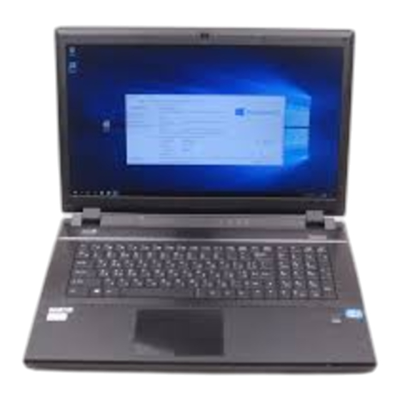
- Page 1 P370EM / P370EM3...
-
Page 2: Chapter 2: Disassembly
Chapter 2: Disassembly Overview This chapter provides step-by-step instructions for disassembling the P370EM / P370EM3 series notebook’s parts and subsystems. When it comes to reassembly, reverse the procedures (unless otherwise indicated). We suggest you completely review any procedure before you take the computer apart. -
Page 3: Maintenance Tools
Disassembly NOTE: All disassembly procedures assume that the system is turned OFF, and disconnected from any power supply (the battery is removed too). Maintenance Tools The following tools are recommended when working on the notebook PC: • M3 Philips-head screwdriver •... -
Page 4: Maintenance Precautions
Disassembly Maintenance Precautions The following precautions are a reminder. To avoid personal injury or damage to the computer while performing a re- moval and/or replacement job, take the following precautions: Power Safety Warning 1. Don't drop it. Perform your repairs and/or upgrades on a stable surface. If the computer falls, the case and other Before you undertake components could be damaged. -
Page 5: Removing The Battery
Disassembly Removing the Battery Figure 1 Battery Removal If you are confident in undertaking upgrade procedures yourself, for safety reasons it is best to remove the battery. Slide the latch and 1. Turn the computer off, remove the AC/DC adapter and turn it over. hold it in place. -
Page 6: Removing The System Memory (Ram)
Disassembly Removing the System Memory (RAM) Figure 7 The computer has three memory sockets for 204 pin Small Outline Dual In-line Memory Modules (SO-DIMM) DDR III RAM-1 Module (DDR3) supporting 1333/1600 MHz. The main memory can be expanded up to 16GB. The total memory size is auto- Removal matically detected by the POST routine once you turn on your computer. -
Page 7: Removing And Installing The Processor
Disassembly Removing and Installing the Processor Figure 10 Processor Removal Processor Removal Procedure 1. Turn off the computer, and turn it over to remove the battery (page 2 - 5), and component bay cover (page 2 - 11). a. Locate the heat sink. 2. -
Page 8: Removing The Vga-1 Card
Disassembly Removing the VGA-1 Card Figure 13 VGA-1 Card 1. Turn off the computer, and turn it over to remove the battery (page 2 - 5) and component bay cover (page 2 - Removal 2. The VGA-1 card will be visible at point on the mainboard (Figure 13a). - Page 9 Disassembly 7. Remove screws & from the VGA-1 assembly. Figure 14 8. If your system includes two video cards you will need to disconnect the cable between the master and slave VGA-1 Card cards (do not forget to reconnect the cable if you are replacing two cards). Removal (cont’d) 9.
-
Page 10: Removing The Vga-2 Card
Disassembly Removing the VGA-2 Card Figure 15 VGA-2 Card 1. Turn off the computer, and turn it over to remove the battery (page 2 - 5), component bay cover (page 2 - 11) and Removal (page 2 - 14). 2. The VGA-2 card will be visible at point on the mainboard (Figure 15a). - Page 11 Disassembly 7. Remove screws & from the VGA-1 assembly. Figure 16 8. Disconnect the VGA cable between the master and slave cards (do not forget to reconnect the cable if you are VGA-2 Card replacing two cards). Removal (cont’d) 9. Carefully lift the VGA-2 card off the mainboard.
Need help?
Do you have a question about the P370EM and is the answer not in the manual?
Questions and answers