Table of Contents
Advertisement
Advertisement
Table of Contents

Related Manuals for Zte ZXV10 W811N


Summary of Contents for Zte ZXV10 W811N
-
Page 1: User Manual
ZXV10 W811N Indoor Wireless Access Point User Manual Version: 1.0 ZTE CORPORATION NO. 55, Hi-tech Road South, ShenZhen, P.R.China Postcode: 518057 Tel: (86) 755 26771900 Fax: (86) 755 26770801 URL: http://ensupport.zte.com.cn E-mail: support@zte.com.cn... -
Page 2: Revision History
ZTE CORPORATION or its licensors may have current or pending intellectual property rights or appli- cations covering the subject matter of this document. Except as expressly provided in any written license between ZTE CORPORATION and its licensee, the user of this document shall not acquire any license to the subject matter herein. -
Page 3: Table Of Contents
Contents Contents Contents 1 Safety Precautions ..........5 2 Product Introduction ..........6 2.1 Product Overview................. 6 2.2 Typical Applications ................6 2.3 Indicator Status Description ..............6 2.4 Interface Description ................7 3 Product Installation ..........7 3.1 Installation Requirements ............... 7 3.2 Product Installation ................ - Page 4 8.6 Setting MLD Snooping Parameters ............44 9 Management Configuration ......... 45 9.1 Managing SNMP Parameters ..............45 9.2 Managing Users .................. 46 9.3 Device Management ................46 9.4 Setting Log Management Parameters ............48 9.5 AP Management .................. 49 9.6 Setting Ping Diagnosis Parameters ............
-
Page 5: Safety Precautions
1 1 1 Safety Safety Precautions Safety Precautions Precautions Installation Use the default power adapter accompanying the equipment. Otherwise, the equipment may be damaged or not be functioning properly. Pay close attention to the load of the power socket or power cable. The overloaded power socket or damaged power cable/connector may trigger electric shock or fire. -
Page 6: Product Introduction
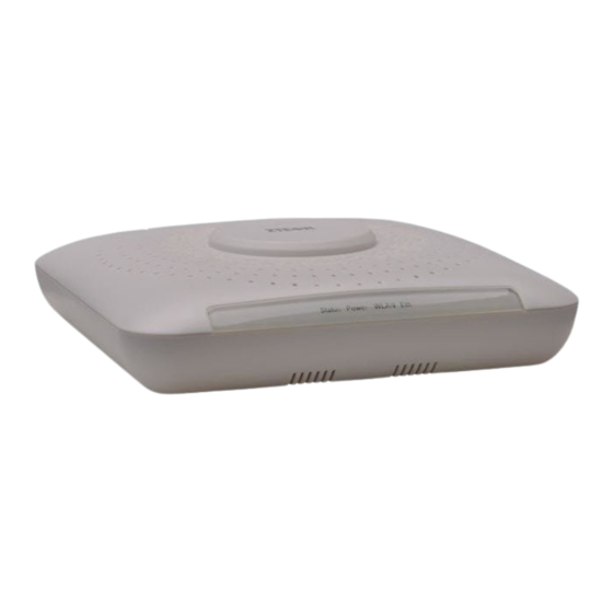
Product Overview ZTE broadband wireless access product works at 2.4 GHz band, and accords with the IEEE 802.11b, 802.11g, and 802.11n standards. It adopts the Orthogonal Frequency Division Mul- tiplexing (OFDM) technology and provides the data transmission rate of 300 Mbps maximally. -
Page 7: Interface Description
Name Status Description The device is starting up, upgrading software, or Blinking detecting an error during self-check. Status The device works normally. The device is powered on. Power The device is powered off or is faulty. The device enables the WLAN function normally. Blinking The device is transmitting data. -
Page 8: Product Installation
A computer equipped with a 10M/100M/1000M Base-TX adaptive fast Ethernet NIC is avail- able. The IP address of the Ethernet NIC is in the same network segment as the IP address of the device, for example, 192.168.0.1. The default IP address of the device is 192.168.0.228. It is recommended that you use the browser of the Microsoft IE 6.0 or a later version and disable the proxy service of the browser. -
Page 9: Computer Configuration
The product supports direct power supply through the standard PoE switch, as shown in the figure below. ZXV10 W811NFollow the steps below to mount the product on the wall. 1. Press the positioning paperboard against the wall to be mounted with the device, as shown in the figure below. -
Page 10: Device Preparation
5. Select the Use the following IP address option and set the IP address of the local com- puter to be in the same network segment as the IP address of the ZXV10 W811N. That is, set the IP address to 192.168.0.x. Wherein, x is a hexadecimal integer ranging from 1 to 227 or 229 to 254. -
Page 11: Logging In To The System
2. (Optional) Click 中 中 中 文 文 文 or English at the upper right corner of the login dialog box to switch the display language. 3. Enter the user name and password, and click Login. The Web page of the ZXV10 W811N is displayed. -
Page 12: Device Status
5 5 5 Device Status Status Device Device Status Viewing Device Device Information Information 5.1 Viewing Viewing Device Information 1. Choose [Status→Device Information] from the main menu. The Device Information page is displayed. 2. View the device information, including device model, device SN, batch number, hardware version, software version, BOOT version, and AP name. -
Page 13: Network Configuration
By default, the ZXV10 W811N works in fit AP mode. To change the AP mode of the ZXV10 W811N, log in to the Web page of the ZXV10 W811N as the administrator and then choose [Administration→AP Management→AP Mode] from the main menu. - Page 14 6.1.2 Setting Setting Broadband Setting Broadband Connection Broadband Connection (Fit Connection (Fit AP) (Fit AP Mode of the device is set to Fit. 1. Choose [Network→WAN→WAN Connection] from the main menu. A page is displayed, as shown in the following figure. 2.
- Page 15 Parameter Description Enables or disables the function of WLAN configuration. Enable VLAN The WLAN ID and 802.1p are used to specify the VLAN and priority of the device. Indicates the VLAN tag of data packets transmitted VLAN ID through the WAN interface. It ranges from 0 to 4094. Indicates the processing priority.
-
Page 16: Wlan Configuration
Parameter Description Indicates the mode of obtaining the global address when Global Address Obtaining IP Version is set to IPv6 or IPv4/v6. The available Mode options are Stateless auto-configuration, Manual, and DHCPv6. Indicates the mode of obtaining the gateway when IP Gateway Obtaining Mode Version is set to IPv6 or IPv4/v6. - Page 17 Channel communication between a wireless AP and a wireless site is determined by the local management environment. All the sites that communicate with the ZXV10 W811N must have the same channel. Indicates the maximum number of access users allowed. Total Maximum Clients...
- Page 18 Parameter Description Beacon Interval By default, it is 100 ms. The available options are Auto, 100%, 90%, 80%, 70%, 60%, 50%, 40%, 30%, 20%, and 10%. By default, it is Transmitting Power 100%. The power level refers to the percentage of the output power to the maximum power.
- Page 19 Parameter Description Choose SSID Indicates the SSID. It ranges from SSID1 to SSID16. Hide SSID Hides the SSID. Enable SSID Enables or disables the SSID. Enables or disables the internal isolation function of Enable SSID Isolation SSID. Indicates the isolation mode. The available options are Isolation Mode Unicast, Broadcast, Multicast, and All.
- Page 20 2. Refer to the following table to set the parameters. Parameter Description Choose SSID Indicates the SSID. It ranges from SSID1 to SSID16. Indicates the authentication type. The available options are Open System (not encrypted), Shared Key, Open System & Shared Key, WPA-PSK, Authentication Type WPA2-PSK, WPA/WPA2-PSK, WPA-EAP, WPA2-EAP, WPA/WPA2-EAP, WAPI-PSK, and...
- Page 21 WPA-PSK WPA refers to Wi-Fi protected access, including WPA-PSK, WPA2-PSK, and WPA/WPA2-PSK. a. On the page as shown in the above figure, select WPA-PSK, WPA2-PSK, or WPA/WPA2-PSK from the Authentication Type drop-down list to enable WPA-PSK encryption. b. Refer to the above table to set the parameters. WPA-EAP a.
- Page 22 WEP refers to wired equivalent privacy. It is one of WLAN security protocols that are used widely. a. Select Shared Key or Open System & Shared Key from the Authentication Type drop-down list, as shown in the following figure. b. Refer to the following table to set the parameters. Parameter Description Enables or disables WEP encryption.
- Page 23 WAPI-PSK a. Select WAPI-PSK from the Authentication Type drop-down list, as shown in the following figure. b. Refer to the following table to set the parameters. Parameter Description Indicates the WAPI key mode. The available WAPI Key Mode options are ASCII and HEX. By default, it is ASCII.
- Page 24 b. Set Certificate Server IP and Certificate Server Port. c. Click Certificate Uploading. On the page that is displayed, select the required certificate file and click Upload. Note: The types of certificate file include AS, AP, and CA. If the AP and CA certificates are required, upload the AP certificate first.
-
Page 25: Setting Parameters
2. Refer to the following table to set the parameters. Parameter Description The available options are SSID/STA and MAC. By default, it is SSID/STA. The switching of control Control Type mode will take effect immediately and the original control mode is cleared. Indicates the SSID. - Page 26 2. Refer to the following table to set the parameters. Parameter Description Indicates the SSID. It ranges from SSID1 to Choose SSID SSID16. The available options are Disabled, Forbid, and Allow, which indicate that SSID channel control is not implemented, and device connections with Mode the required MAC addresses are forbidden and allowed respectively.
- Page 27 2. Select the required SSID from the Choose SSID drop-down list. Then, view the details of the associated devices corresponding to the selected SSID. By default, the system displays the details of the associated devices corresponding to SSID1. Note: Refresh refresh the current settings of the device. Click Refresh Refresh 6.2.7 Scanning...
- Page 28 6.2.8 Setting Setting WMM Setting WMM Parameters Parameters Parameters 1. Choose [Network→WLAN→WMM] from the main menu. The WMM page is displayed, as shown in the following figure. 2. Refer to the following table to set the parameters. Parameter Description Choose AC The available options are VO, VI, BE, and BK.
-
Page 29: Address Management
2. Refer to the following table to set the parameters. Parameter Description Enables or disables the function of flood attack Enable Flood Attack Detection detection. Enables or disables the function of snooping attack Enable Snoof Attack Detection detection. Aging Time Indicates the aging time. - Page 30 DHCP Start IP Address make sure that the address is in the same network segment as the IP address of the ZXV10 W811N. Indicates the end IP address allocated for the DHCP server. To change the start IP address or end IP address,...
-
Page 31: Setting Static Routing Parameters
Parameter Description Indicates the lease time, that is, the time of the DHCP server in leasing the IP address. The unit is second. By default, it is 86400s. The lease time refers to the time of the client in leasing an Lease Time IP address from the IP address pool that supports dyna mic allocation. -
Page 32: Enabling Ipv6
2. Refer to the following table to set the parameters. Parameter Description WAN Connection Selects the required interface. Indicates the destination network address to be Network Address accessed. Indicates the subnet mask of the destination network Subnet Mask address to be accessed. Gateway Indicates the gateway (next hop) IP address. -
Page 33: Safety Configuration
7 7 7 Safety Configuration Configuration Safety Safety Configuration Setting Firewall Firewall Parameters Parameters 7.1 Setting Setting Firewall Parameters 1. Choose [Security→Firewall] from the main menu. The Firewall page is displayed, as shown in the following figure. 2. Refer to the following table to set the parameters. Parameter Description Enables or disables the function of anti-attack... - Page 34 1. Choose [Security→IP Filter] from the main menu. The IP Filter page is displayed, as shown in the following figure. 2. Refer to the following table to set the parameters. Parameter Description Enable Enables or disables the function of IP address filter. Indicates the protocol name.
-
Page 35: Setting Mac Filter
Parameter Description Indicates the port of the IP address of the end source End Source port (LAN side). Start Destination port Indicates the port of the start destination IP address. End Destination port Indicates the port of the end destination IP address. Indicates the ingress interface. -
Page 36: Setting Alg Switch
Parameter Description Enables or disables the function of MAC filter. By Enable default, this function is disabled. Selects a mode. The available options are Access Mode and Discard. Selects a type. The available options are Bridge, Type Route, and Bridge + Route. Indicates the protocol name. -
Page 37: Application Configuration
8 8 8 Application Application Configuration Application Configuration Configuration Setting UPnP UPnP 8.1 Setting Setting UPnP AP Mode of the device is set to Fat. The universal plug and play (UPnP) supports network connection with zero configuration and automatic discovery of various network devices. When the UPnP function is enabled, the devices that support this function are allowed to dy- namically access the network, obtain IP addresses, and transmit their performance data. -
Page 38: Qos Settings
Choose [Application→DNS Service→Domain Name] from the main menu. The Do- main Name page is displayed, as shown in the following figure. b. In the Domain Name text box, enter a domain name, for example, ZTE. c. Click Submit to submit the current settings. - Page 39 In the QoS framework, the concept of class of service is introduced to QoS mapping. After QoS is enabled, the ZXV10 W811N can completely control the data packets in both ingress and egress directions. For the data packets in the ingress direction, the domain mapping (ToS and priority) needs to be converted to queue.
- Page 40 8.3.2 Setting Setting Setting Classification Classification Rules Classification Rules Rules 1. Choose [Application→QoS→Classification] from the main menu. The Classification page is displayed, as shown in the following figure. 2. Refer to the following table to set the parameters. Parameter Description Enables or disables the function of setting QoS Enable classification rules.
- Page 41 Parameter Description Source MAC Address Indicates the source MAC address of packets. Indicates the tag value (user priority) of VLAN packets. It 802.1p ranges from 0 to 7. The value 0 indicates that the priority is not set. The greater the value, the higher the priority. Indicates the upper and lower thresholds for the Destination Port MIN/MAX destination port of packets.
-
Page 42: Setting Time Management Parameters
3. Click Add to submit the current settings. Setting Queue Queue Management Management Parameters Parameters 8.3.3 Setting Setting Queue Management Parameters Note: The default queue management algorithm of the system is SP. Queue 8 is the default queue and is enabled by default. 1. -
Page 43: Igmp Settings
2. Refer to the following table to set the parameters. Parameter Description Current Date and Time Displays the current date and time of the device. Selects the time zone to which the device belongs Time Zone according to the actual condition. Sets the address or domain name of the primary Primary NTP Server Address NTP server. - Page 44 2. Refer to the following table to set the parameters. Parameter Description Enable IGMP Proxy Enables or disables the function of IGMP proxy. WAN Connection Selects the required WAN connection. 3. Click Submit to submit the current settings. 8.5.2 Setting Setting Setting IGMP IGMP...
-
Page 45: Management Configuration
2. Enable or disable the function of MLD snooping. 3. Click Submit to submit the current settings. 9 9 9 Management Configuration Configuration Management Management Configuration 9.1 Managing Managing SNMP Managing SNMP Parameters SNMP Parameters Parameters 1. Choose [Administration→SNMP] from the main menu. The SNMP page is displayed, as shown in the following figure. -
Page 46: Managing Users
3. Click Submit to submit the current settings. Managing Users Users 9.2 Managing Managing Users 1. Choose [Administration→User Management] from the main menu. The User Manage- ment page is displayed, as shown in the following figure. 2. Refer to the following table to set the parameters. Parameter Description User Right... - Page 47 2. Soft rest the device or restore the default settings of the device. Click Reboot to restart the device. Click Restore Default to restore the default settings of the device and then restart the device. 9.3.2 Setting Setting Setting Version Version Version Upgrade Upgrade...
- Page 48 2. Select the required backup configuration file or import a configuration file. Exporting a configuration file Click Backup Configuration to back up the configuration file of the device. Importing a configuration file a. Click Browse to select the required configuration file of the device. b.
-
Page 49: Ap Management
2. Refer to the following table to set the parameters. Parameter Description Enables or disables the function of log server Log Enable management. By default, this function is disabled. Indicates the log level. The levels from low to high are Debug, Informational, Notice, Warning, Error, Log Level Critical, Alert, and Emergency. - Page 50 2. Select the required AP mode (Fat or Fit). By default, the AP mode is Fit. Note: After the AP mode is switched, the device will automatically restart. 3. Click Submit to submit the current settings. Setting AP AP AP Name Name 9.5.2 Setting Setting...
- Page 51 4. Click Submit. Then, the ping result is displayed in the lower text box. A A A During the installation or use of the ZXV10 W811N, some problems may occur. In this case, refer to the following solutions to solve the problems. If some problems still persist, contact the corresponding carrier for help.
- Page 52 Question Solution Check whether interference of same devices exists. To be specific, check whether wireless devices exist around. If yes, power off the devices and check whether the interference is reduced. Alternatively, you can mask the devices that gener ate interference or adjust their locations. Check whether interference of other devices exists.
-
Page 53: B Technical Specifications
Question Solution You can do as follows to solve this problem: Check whether Working Mode of the two devices is Bridge. Check whether the MAC address of the remote end is correct. Why does the connection between Check whether Country/Region of the two devices is the two devices fail to be same. - Page 54 Working humidity: 5% to 95% IP degree IP degree: IP30 Certification passed CCCi, CE, Wi-Fi, radio transmission equipment model authorization ZTE reserves the right of modifying the technical parameters of this manual without previous notice. C C C Setting Computer Computer Wireless...
- Page 55 3. In the Wireless Network Connection Properties dialog box, click the General tab. Then, set the IP address of the wireless NIC and the address of the DNS server. Alternatively, you can obtain these addresses in DHCP mode. 4. In the Wireless Network Connection Properties dialog box, click the Wireless Networks tab.
- Page 56 5. On the Association tab, set SSID in the Network name text box. Note that this SSID must be the same as that configured for the terminal and is case sensitive. Suppose that the terminal uses WPA-PSK encryption and the encryption key is 12345678. Then, set Network Authentication to WPA-PSK and Data encryption to TKIP.
- Page 57 6. In the dialog box as shown in the above figure, click View Wireless Networks to display the wireless network list. Then, check whether the new wireless network is available. If not, click Refresh network list on the left. After selecting the required wireless network, click Connect at the lower part of the dialog box, as shown in the following figure.
Need help?
Do you have a question about the ZXV10 W811N and is the answer not in the manual?
Questions and answers