Table of Contents
Advertisement
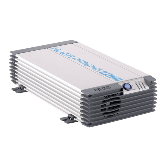
SinePower MSP 702, MSP 704,
MSP 1012, MSP 1024, MSP 1512,
MSP 1524, MSP 2012, MSP 2024,
MSP 2512, MSP 2524
DE 10 Sinus Wechselrichter
Bedienungsanleitung
EN 34 Sine wave inverter
Instruction Manual
FR 56 Onduleur sinusoïdal
Notice d'emploi
ES 82 Convertidor de ondas seno
Instrucciones de uso
IT 107 Inverter sinusoidale
Istruzioni per l'uso
NL 132 Sinus ondulator
Gebruiksaanwijzing
DA 155 Sinus ensretter
Betjeningsanvisning
SV 177 Sinus växelriktare
Bruksanvisning
NO 199 Sinus vekselretter
Bruksanvisning
FI 221 Sinus -vaihtosuuntaaja
Käyttöohje
Advertisement
Table of Contents


Need help?
Do you have a question about the SinePower MSP 702 and is the answer not in the manual?
Questions and answers