Aprilaire 800 Installation & Maintenance Instructions Manual
Residential steam humidifier
Hide thumbs
Also See for 800:
- User manual ,
- Installation & maintenance instructions manual (64 pages) ,
- Owner's manual (32 pages)
Table of Contents
Advertisement
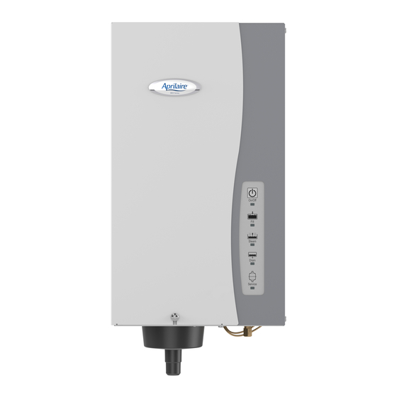
Model 800 Residential Steam Humidifier
Installation & Maintenance Instructions
Table of ConTenTS
Safety Cautions . . . . . . . . . . . . . . . . . . . . . . . . . . . . . . . . . . . . . . . . . . 2
Materials list . . . . . . . . . . . . . . . . . . . . . . . . . . . . . . . . . . . . . . . . . . . 2
Principles of operation . . . . . . . . . . . . . . . . . . . . . . . . . . . . . . . . . . . 3
Specifications & Dimensions . . . . . . . . . . . . . . . . . . . . . . . . . . . . . 3
Installation Instructions . . . . . . . . . . . . . . . . . . . . . . . . . . . . . . . . . . 5
Choosing a Location . . . . . . . . . . . . . . . . . . . . . . . . . . . . . . . . . . . . . 5
- Dispersion Tube . . . . . . . . . . . . . . . . . . . . . . . . . . . . . . . . . . . . . . 5
- Humidifier . . . . . . . . . . . . . . . . . . . . . . . . . . . . . . . . . . . . . . . . . . 7
Prepare Humidifier for Mounting . . . . . . . . . . . . . . . . . . . . . . . . . . . 8
Install Steam Dispersion Tube . . . . . . . . . . . . . . . . . . . . . . . . . . . . . 8
Mount Humidifier . . . . . . . . . . . . . . . . . . . . . . . . . . . . . . . . . . . . . . . 8
Install Steam Hose . . . . . . . . . . . . . . . . . . . . . . . . . . . . . . . . . . . . . . 8
Model 800 Residential Steam Humidifier
ReaD anD SaVe THeSe InSTRUCTIonS
Supply Water . . . . . . . . . . . . . . . . . . . . . . . . . . . . . . . . . . . . . . . . . . . 8
Drain Line . . . . . . . . . . . . . . . . . . . . . . . . . . . . . . . . . . . . . . . . . . . . . . 9
Automatic Digital Control and Control Wiring . . . . . . . . . . . . . . . . . 9
Electrical Power Wiring & Shut-off Switch . . . . . . . . . . . . . . . . . . 10
Start-up Procedure . . . . . . . . . . . . . . . . . . . . . . . . . . . . . . . . . . . . . 14
Sequence of operation . . . . . . . . . . . . . . . . . . . . . . . . . . . . . . . . . . 14
operating Modes . . . . . . . . . . . . . . . . . . . . . . . . . . . . . . . . . . . . . . . 15
Shut Down Procedure . . . . . . . . . . . . . . . . . . . . . . . . . . . . . . . . . . . 15
Display Panel . . . . . . . . . . . . . . . . . . . . . . . . . . . . . . . . . . . . . . . . . . 16
Maintenance . . . . . . . . . . . . . . . . . . . . . . . . . . . . . . . . . . . . . . . . . . . 17
Checking System operation & Troubleshooting . . . . . . . . . . . . 18
Replacement Parts . . . . . . . . . . . . . . . . . . . . . . . . . . . . . . . . . . . . . . 21
Advertisement
Table of Contents

Related Manuals for Aprilaire 800


Summary of Contents for Aprilaire 800
-
Page 1: Table Of Contents
Model 800 Residential Steam Humidifier Model 800 Residential Steam Humidifier Installation & Maintenance Instructions Table of ConTenTS Safety Cautions . . . . . . . . . . . . . . . . . . . . . . . . . . . . . . . . . . . . . . . . . . 2 Supply Water . -
Page 2: Safety Cautions
SafeTy CaUTIonS CaUTIon aTTenTIon InSTalleR Read this manual before installing. This product must be installed by qualified HVAC and electrical contractors and in compliance with local, state, federal, and governing codes. Improper installation can cause property damage, severe personal injury, or death as a result of electric shock, burns, or fire. Read all cautions and instructions. -
Page 3: Principles Of Operation
Model 800 humidifier one week or more of operation to reach rated capacity, especially if it is wired to operate on 120 volts. when operating on 240 volts, the Model 800 usually will reach nominal capacity within a few hours, even with lower conductivity water. - Page 4 SPeCIfICaTIonS & DIMenSIonS (ConTInUeD) fIGURe 2 – Humidifier & Dispersion Tube Dimensions 3" Mounting Plate 8 7/8" to first opening 1 3/4" Fill Cup 7 7/8" 3" sq 3 3/8" 1 5/8" 1" dia 3 3/8" 4 1/4" 8 1/4" 5 3/4"...
-
Page 5: Installation Instructions
HVAC system heat call . When installing the humidifier in a system with variable speed blower, determine absorption distance based on airflow at the lowest speed . Call Aprilaire Tech Support at 1-800-334-6011 for additional information on absorption . - Page 6 InSTallaTIon InSTRUCTIonS (ConTInUeD) elevation The preferred location for the dispersion tube is higher than the humidifier so that the steam hose has a constant downward slope of at least 2” per foot from the dispersion tube to the humidifier . If hard pipe is used, the slope can be 1/4” per foot . With the constant downward slope, any condensation that forms in the steam hose will drain back into the steam canister .
-
Page 7: Humidifier
InSTallaTIon InSTRUCTIonS (ConTInUeD) fIGURe 5 3/4" x 1" Reducing Coupling Dispersion Tube Steam Hose 1-1/2" Hose Clamp 1" Copper Pipe 1-1/2" Hose Clamp Steam Hose Humidifier 90-1527 HUMIDIfIeR fIGURe 6 – Clearances Do not mount humidifier in a location where ambient temperature exceeds 120°f or where freezing temperatures may occur. -
Page 8: Prepare Humidifier For Mounting
InSTallaTIon InSTRUCTIonS (ConTInUeD) PRePaRe HUMIDIfIeR foR MoUnTInG Unpack carton . Open front panel by removing screw and lifting panel up and away from humidifier . Disconnect three wires from top of canister by pulling straight up . The two large wires are the electrode conductors . The smaller wire is connected to the high water level sensor . Remove canister by pulling it up and out of drain assembly . -
Page 9: Drain Line
. If airflow verification is desired, install optional airflow proving switch Part #4592 in duct . The high humidity limit switch and the airflow proving switch are wired in series with the ADHC (humidistat) circuit . See figure 7 . fIGURe 7 – Model 800 accessory wiring MODEL 62 DIGITAL HUMIDIFIER CONTROL... -
Page 10: Electrical Power Wiring & Shut-Off Switch
Humidifier draws 11 .5 amps ±10% . Use 12 .7 amps when sizing circuit . The Model 800 Steam Humidifier is shipped from the factory wired for 240 VAC operation, but it can operate on 120, 208 or 240 VAC . - Page 11 InSTallaTIon InSTRUCTIonS (ConTInUeD) fIGURe 8 – 240 VaC wiring Diagram NOTE: MODEL 800 IS SHIPPED FROM THE FACTORY WIRED IN MAIN POWER SWITCH THE 240 VOLT CONFIGURATION. (NOT PROVIDED) TERMINAL N, L2 BLOCK POWER RELAY CONTACTS JUMPER WIRE BLK / WHT...
- Page 12 InSTallaTIon InSTRUCTIonS (ConTInUeD) fIGURe 9 – 208 VaC wiring Diagram NOTE: MODEL 800 IS SHIPPED FROM THE FACTORY WIRED FOR 240 VOLTS. THE BLACK / WHITE WIRE FROM L1 MAIN POWER SWITCH (NOT PROVIDED) MUST BE MOVED TO THE 208 VOLT TERMINAL FOR 208 VOLT OPERATION.
- Page 13 InSTallaTIon InSTRUCTIonS (ConTInUeD) fIGURe 10 – 120 VaC wiring Diagram NOTE: MODEL 800 IS SHIPPED FROM THE FACTORY WIRED FOR 240 VOLTS. MAIN POWER SWITCH THE BLACK / WHITE WIRE FROM L1 (NOT PROVIDED) MUST BE MOVED TO THE 120 VOLT TERMINAL FOR 120 VOLT OPERATION.
-
Page 14: Start-Up Procedure
STaRT-UP PRoCeDURe 1 . Once the supply water, drain, steam hose, electrical power and control wiring connections are complete, make sure canister is fully seated into drain valve and three wire connectors on top of canister are secure . (High water probe wire and two interchangeable electrode wires .) 2 . -
Page 15: Operating Modes
oPeRaTInG MoDeS When the humidifier is powered and turned on, the “On/Off” light is illuminated green . During fill cycles, the “Fill” light illuminates green . When the humidifier is turned on, any time the ADHC sends a call for humidity, the Steam light illuminates green . Any time the drain valve is activated, the “Drain”... -
Page 16: Display Panel
DISPlay Panel Green lights indicate normal operation . Yellow Steam light indicates humidifier is operating at less than rated capacity . Yellow Steam light also indicates humidifier is in Test mode . Flashing red Service light indicates canister has reached the end of its life and needs to be replaced . Solid red lights indicate humidifier has shut down and requires service . -
Page 17: Maintenance
. To RePlaCe THe CanISTeR Replace the canister annually and when prompted by the “Service” light . Use Only Genuine Aprilaire Model 80 Canister . 1 . Press On/Off switch to turn humidifier off . -
Page 18: Checking System Operation & Troubleshooting
The following troubleshooting guide is intended to help diagnose and resolve general operational problems with Model 800 Humidifier . If a problem persists, call Aprilaire Tech Support toll-free at 1-800-334-6011 . Please be prepared to describe the exact nature of the problem . - Page 19 CHeCkInG SySTeM oPeRaTIon & TRoUbleSHooTInG (ConTInUeD) Table 5 – Troubleshooting Guide Problem Possible Cause action General operating Field-wired terminal Check L1, N/L2 and Ground connections . problems . Humidifier connections . Check HUMIDISTAT and FAN PACK Terminal connections . will not turn on or turn off .
- Page 20 CHeCkInG SySTeM oPeRaTIon & TRoUbleSHooTInG (ConTInUeD) Table 5 – Troubleshooting Guide (continued) Problem Possible Cause action Humidifier is filling and Internal wiring connections . Make sure blue/white wire jumpers (2) connecting Control PCB and Current Sensing draining at the same time . PCB are secure and properly oriented .
-
Page 21: Replacement Parts
Parts shown are for Model 800 Humidifiers manufactured after September 2011 (inlet valve extends out bottom of housing .) For parts for Model 800 humidifiers manufactured prior to October 2011 (inlet valve entirely inside housing) refer to Aprilaire Humidifier Replacement Parts & Price List . - Page 22 4990 Fill Cup Cap 4975 Membrane Switch 4991 Steam Dispersion Tube & Screws 5306 Universal Transformer, Model 800 Automatic Digital Control for Model 800 4977 Power Relay Steam Canister and O-Ring 4978 Electrode Wire (1) 5308 Transformer Terminal Block 4979...
Need help?
Do you have a question about the 800 and is the answer not in the manual?
Questions and answers