Aprilaire 800 Series - Steam Humidifier Manual
- User manual ,
- Installation & maintenance instructions manual (64 pages) ,
- Owner's manual (32 pages)
Advertisement
- 1 INTRODUCTION
- 2 PRINCIPLES OF OPERATION
- 3 SEQUENCE OF OPERATION
- 4 INSTALLATION OPTIONS AND EFFECT OF WATER CHARACTERISTICS
- 5 OPERATING MODES
- 6 END OF SEASON/PERIOD OF INACTIVITY SHUT-DOWN
- 7 DISPLAY PANEL
- 8 OPERATING INSTRUCTIONS – MODEL 62 AUTOMATIC DIGITAL HUMIDIFIER CONTROL
- 9 OPERATING INSTRUCTIONS – MODEL 65 MANUAL DIGITAL HUMIDISTAT
- 10 OPERATING INSTRUCTIONS – MODEL 63 AUTOMATIC DIGITAL MODULATING CONTROL
- 11 ADDITIONAL INFORMATION
- 12 MAINTENANCE
- 13 SAFETY CAUTIONS
- 14 Documents / Resources
INTRODUCTION
We appreciate your business and are pleased to add your name to our growing list of customers
You have invested in the highest quality equipment available Aprilaire manufactures whole-house indoor air quality products and is a recognized leader in the heating and air conditioning industry
Your humidifier will require periodic maintenance to assure continued consistent performance
Please take a few minutes and read this booklet This will familiarize you with the benefits you will receive from the humidifier and help you understand the routine maintenance that will be required
Be sure to register your humidifier warranty online at: www.aprilaire.com/warranty
Genuine Aprilaire Replacement Steam Canisters are available from your installing contractor or from most other heating and air conditioning contractors in your area. Use the dealer locator on our web site (www.aprilaire.com).
PRINCIPLES OF OPERATION
The Aprilaire® Steam Humidifier delivers humidity in the form of steam to the conditioned space via the HVAC system duct or Aprilaire Fan Pack The humidifier generates steam by energizing 2 electrodes that extend into a canister of water Current flowing between the electrodes causes the water to boil, creating steam Water is introduced to the humidifier through a fill valve to a fill cup located in the top of the cabinet The fill cup serves as an overflow reservoir and provides an air gap between the humidifier and water source The steam canister is filled from the bottom The canister is seated in a drain cup assembly which includes a drain valve The drain and fill valves work together to maintain water level in the canister to deliver the rated steam capacity based on the electrical conductivity of the water and to temper drain water See FIGURE 1 for representation of fill and drain system and canister
Steam is delivered into the airstream through a dispersion tube mounted in the HVAC system ductwork Openings in the dispersion tube are fitted with "tubelets™" which extend into the center of the tube The design of the dispersion tube and tubelets distribute steam over a wide area in the duct and direct any condensed moisture back into the steam hose

SEQUENCE OF OPERATION
When the humidifier control detects the need for humidity, and provided the humidifier is turned on and the HVAC system blower is operating, the internal controller in the humidifier energizes the electrodes and measures the current flowing through the water between them The controller adjusts water level in the canister via a fill valve and a drain valve to maintain a constant current The operating water level in the canister depends on the mineral content of the water which determines conductivity
INSTALLATION OPTIONS AND EFFECT OF WATER CHARACTERISTICS
Your steam humidifier can be powered with a 120, 208 or 240 volt circuit and operated at either 115 or 160 amps The higher the voltage and amperage the higher the potential output The operating voltage and amperage are set by your installing contractor to meet the humidification needs of your home
| Amperage | Voltage | Maximum steam capacity (gal/day) |
| 115 | 120V | 115 |
| 208V | 205 | |
| 240V | 233 | |
| 160 | 120V | 160 |
| 208V | 300 | |
| 240V | 346 |
It may take several days for the humidifier to reach rated capacity depending on the input voltage and the electrical conductivity of the water. 120 volt systems take longer to reach rated capacity than 240 volt systems The humidifier should always be plumbed to cold water but the water can be softened or unsoftened "Hard" water, which has a high mineral content, and softened water generally have higher conductivity than naturally soft water Systems plumbed to higher conductivity water will reach capacity sooner than systems plumbed to low conductivity water As the humidifier operates, minerals build up in the canister, which increases the conductivity of the water With a new canister, allowing the humidifier to operate continuously (along with the HVAC system blower) will allow it to reach rated capacity in the shortest amount of time
Canister life is highly dependent on water quality Canisters in systems plumbed to water with high concentrations of suspended and dissolved solids will not last as long as canisters operating on water with less minerals
Two canisters are available, the Model 80 and Model 80LC, optimized for different water types Contact your HVAC dealer for canister selection
NOTE: Amperage, voltage and plumbing changes should be made by a heating and air conditioning contractor
OPERATING MODES
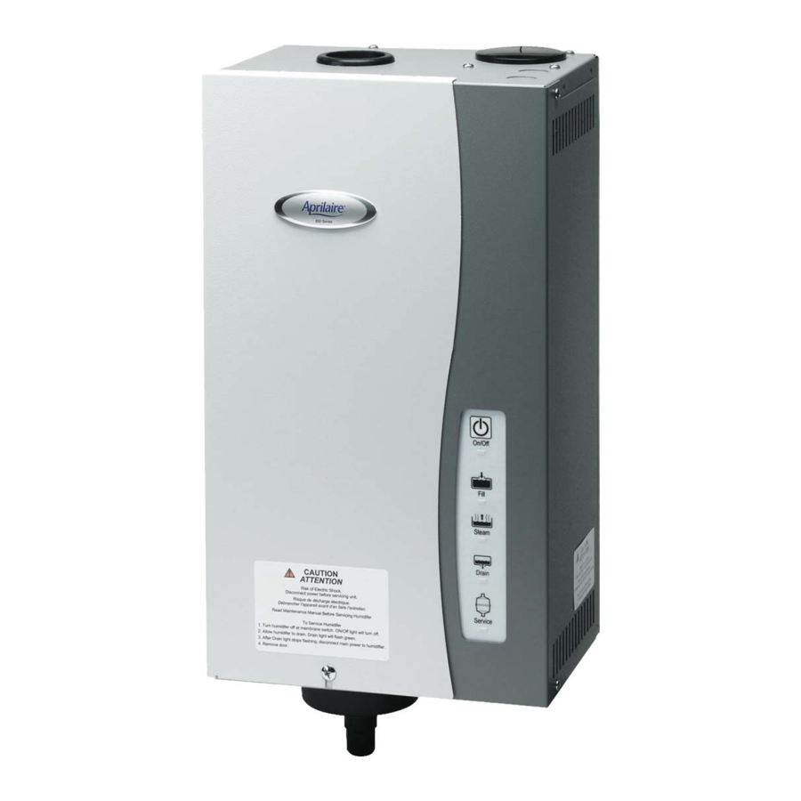
When the humidifier is powered and turned on, the "On/Off" light is illuminated green
When the canister is being filled or replenished with water, the "Fill" light illuminates green
When the canister is being drained, the "Drain" light illuminates green
During initial start up with a new canister, the humidifier may run through a series of fill/drain cycles until the conductivity of the water is in a range that allows normal operation During this time, the "Steam" light illuminates green If the humidifier cannot produce steam at the rated level after 168 hours of operation, the "Steam" light illuminates yellow The humidifier continues to operate in this state until the rated output is reached
The conductivity of naturally soft water, hard water, and softened water changes as the water heats up, and the internal controller adjusts the water level to maintain a nominal current between the electrodes Over the life of the canister, minerals that build up on the electrodes will reduce their effective surface area and affect the resistance between them The operating water level will increase with use until it reaches the high water level probe At that point, the "Service" light will flash red indicating that the canister should be replaced The humidifier will continue to operate but with reduced output
When the humidifier begins a drain cycle, the fill valve opens to introduce cold water into the canister This is done to prevent hot water from entering the drain The drain valve remains open for 4 minutes to allow all water to drain from the canister
Any time power is disconnected or the humidifier is turned off, the internal timer for start-up and drain cycles is reset
If the humidifier has operated 168 hours without a drain cycle, the drain valve will open and drain the canister Normal operation will continue
If the humidifier is operating and a power failure occurs, once power is restored, the "On/Off" light will flash green for one minute, then the humidifier will turn on
If the humidifier has excessive drain cycles or cannot reach desired humidity, contact your heating and air conditioning dealer for service
END OF SEASON/PERIOD OF INACTIVITY SHUT-DOWN
If the humidifier does not receive a call to operate in 72 hours, the humidifier controller drains the canister, and the drain valve will remain open for 30 minutes The drain light will remain on until there is a humidity call or 24 hours have elapsed The humidifier will resume normal operation when a call for humidity is made
DISPLAY PANEL
| TABLE 1 – DISPLAY PANEL | ||
| Indicator | Light | Function |
 | Off | Humidifier is turned OFF or not receiving power |
| Solid Green | Humidifier is turned ON | |
| Flashing Green | Humidifier is preparing to turn ON Occurs if power is disconnected, then restored with switch ON Flashes for 1 minute | |
 | Solid Green | Normal operation Fill valve is energized allowing water to flow into canister via fill cup (Does not illuminate when tempering water during drain cycle) |
| Flashing Green | Fill and drain valves are pulsing to dislodge mineral build-up in canister Flashes 10 times in 4 seconds | |
| Solid Red | Fault mode Indicates canister needs water but cannot fill Humidifier shuts down Occurs if high water probe does not detect water after fill valve is energized for 40 minutes Call your heating and air conditioning dealer for service | |
 | Solid Green | Normal operation Humidistat is calling for steam and humidifier is operating |
| Solid Yellow | Normal operation Humidifier is operating but is not delivering steam at rated capacity Occurs if humidifier has operated for 168 hours at less than rated capacity due to low water conductivity Light will turn green once water conductivity increases and humidifier is delivering rated capacity If yellow light persists, consult your heating and air conditioning dealer for canister options | |
 | Flashing Green | Humidifier is preparing to drain (Fill valve is open tempering water in canister) Occurs when humidifier is turned OFF, at end of season drain (72 hours with no operation) and during forced drain down (168 hours of operation with no drain activity) |
| Fill and drain valves are pulsing to dislodge mineral build-up in canister Flashes 10 times in 4 seconds | ||
| Solid Green | Drain valve is energized and open, draining canister Valve remains energized for 4 minutes | |
| Indicates end of season shut-down Occurs if humidifier does not receive call for humidity in 72 hours Light remains on for 24 hours Humidifier will turn on with the next call for humidity | ||
 | Flashing Red | Canister has reached the end of its life and needs to be replaced Occurs after humidifier has operated for at least 168 hours and for an additional 24 hours at a current level below 75% of the maximum operating current Humidifier continues to operate, but at reduced capacity |
| Solid Red | Operational problem with humidifier Humidifier shuts down Occurs when unit detects over-current which can be caused by failure to drain or other system failures Call your heating and air conditioning dealer for service | |
OPERATING INSTRUCTIONS – MODEL 62 AUTOMATIC DIGITAL HUMIDIFIER CONTROL
The Model 62 Automatic Digital Humidifier Control (ADHC) offers 2 modes of operation, Automatic or Manual An explanation of both modes follows (See FIGURE 2 for Automatic Mode See FIGURE 3 or Manual Mode)
When in the Automatic Mode, this system offers the following benefits:
- You will receive the optimum amount of humidity so that your home and its furnishings are protected from the damaging effects of excess condensation or low humidity during the heating season. The ADHC automatically adjusts your home's humidity based on the outdoor temperature, increasing the time maximum comfort is maintained
- Simple operation with few adjustments. In the Automatic Mode, the ADHC eliminates the need to manually adjust the control when outdoor temperature changes It also eliminates the need to turn the dial setting to "OFF" during the summer season
MODEL 62 AUTOMATIC DIGITAL HUMIDIFIER CONTROL INDICATOR LIGHTS
Call Dealer for Service: The red light indicates that the control is not operating normally and that service is required
Humidifier ON: The green light indicates that the control is operating normally and sending a call for humidity to the humidifier
BLOWER ACTIVATION
The Blower Activation switch is set to the "ON" position to allow the humidifier control to activate the HVAC fan for maximum humidification
If the HVAC system has been idle for 1 hour, the humidifier control will activate the HVAC system fan to sample the air for 3 minutes If the RH is lower than the set point, the humidifier control will activate the humidifier and keep the fan running The humidifier will continue to operate for 2 hours or until the humidification set point is reached
If the RH set point has not been reached by the end of a call for heat, the control will continue to operate the humidifier and the HVAC fan until the humidification set point is reached or 2 hours have elapsed
When the Blower Activation switch is in the "OFF" position, the humidifier control will only operate the humidifier if humidity is required and the HVAC system fan is operating or the HVAC system is producing heat NOTE: If used in conjunction with an Aprilaire 8570 Communicating
Thermostat, and the Blower Activation feature is desired, DO NOT wire the A B communication terminals
AUTOMATIC MODE

Your Aprilaire ADHC must be installed in the cold air return duct During the first heating season, your humidifier control needs to be set initially to match your home's condition Please follow these steps when adjusting your control (refer to FIGURE 2)
- Turn the dial setting knob to "5," which is within the normal range During the next 24 to 48 hours it may be necessary to adjust the dial for more or less humidity, depending on your personal comfort and home's requirements Refer to TABLE 2 – ADHC OPERATION GUIDE
- During the coldest portion of the first heating season, minor adjustments may be necessary This is dependent upon your home's construction Refer to TABLE 2 – ADHC OPERATION GUIDE
The humidity in your home will now be accurately controlled to meet your needs and should not need further adjustment during future heating seasons
Make note of the dial setting in the event you temporarily move the knob to "OFF" when performing annual maintenance of your Aprilaire humidifier
Your humidifier is a precision system that will accurately maintain the humidity in your home For every 2°F change in outdoor temperature, the Model 62 Automatic Digital Humidifier Control will automatically adjust the indoor humidity by 1%
The Model 62 Automatic Digital Humidifier Control will accurately control the humidity in your home to a maximum of 45%
The humidity values in TABLE 3 are targets based on outdoor temperature and the Digital Humidifier Control setting The actual humidity may vary due to conditions in the home (cooking, showering, etc)
TABLE 2 – ADHC OPERATION GUIDE
| Condition | Solution |
| Condensation on windows | Reduce the setting on the control dial by 1 increment |
| Lack of humidity | Increase the setting on the control dial by 1 increment |
| Humidifier does not turn on | Make certain HVAC blower is operating Turn dial to "Test/Reset" If unit still does not operate, consult a heating contractor Display will flash software revision level eg "r1," if the control knob is left in test/reset for longer than 1 minute |
| Humidifier will not shut off | Turn control dial to "Off" If unit continues to produce steam (steam light ON), disconnect main power to turn off the humidifier and consult a heating contractor |
| Test mode | Make certain HVAC blower is operating System operation is checked by setting the knob to "Test/ Reset" Humidifier will operate for 1 minute |
| Red "Call Dealer for Service" light flashes (FIGURE 2) | Note the error code on the display (E1, E2, E3 or E4) and call your heating and air conditioning dealer for service |
TABLE 3 – % RELATIVE HUMIDITY GUIDE
| Outdoor Temperature (°F) | ||||||||
| -10°F | 0°F | 10°F | 20°F | 30°F | 40°F | |||
| Dial Setting | 1 | 10% | 10% | 10% | 15% | 20% | 25% | Relative Humidity (%) |
| 2 | 10% | 10% | 15% | 20% | 25% | 30% | ||
| 3 | 10% | 15% | 20% | 25% | 30% | 35% | ||
| 4 | 15% | 20% | 25% | 30% | 35% | 40% | ||
| 5 | 20% | 25% | 30% | 35% | 40% | 45% | ||
| 6 | 25% | 30% | 35% | 40% | 45% | 45% | ||
| 7 | 30% | 35% | 40% | 45% | 45% | 45% | ||
MANUAL MODE

When the humidistat is in Manual Mode (see FIGURE 3 – internal switch in the "MAN" position and "M" in the display), it is important to anticipate a drop in outdoor temperature and reduce the setting accordingly to avoid excess condensation For example, with an outdoor temperature of 20°F, the recommended setting will be 35% If the temperature is expected to fall to 0°F that evening, reduce the setting to 25% several hours prior to the temperature change
See TABLE 4 for the recommended settings These settings represent a compromise between humidity levels within the range of comfort and protection from window condensation For example, a 50% indoor humidity in wintertime may be ideal for comfort, but would result in damaging condensation Thus, observing recommended humidity levels on the humidifier control is important Condensation on the inside surface of windows in the form of fogging or frost is indicative of over-humidification This same condensation can occur in other areas of the home, resulting in damage
| TABLE 4 – OUTDOOR TEMPERATURE AND RECOMMENDED INDOOR RH SETTING | |
| Outdoor Temperature | Recommended Indoor RH Setting |
| +40°F | 45% |
| +30°F | 40% |
| +20°F | 35% |
| +10°F | 30% |
| 0°F | 25% |
| -10°F | 20% |
| -20°F | 15% |
TEST/RESET
The "Test/Reset" setting allows the humidifier operation to be checked even if there is no call for humidity See "Check the Humidifier Operation"
CHECK THE HUMIDIFIER OPERATION
DIGITAL HUMIDIFIER CONTROL
Set the knob to "Test/Reset," make sure that the water saddle valve is open and that the humidifier is on The HVAC fan must be running for the humidifier to function The humidifier will only operate for 1 minute in test mode Reduce the humidifier control setting to the recommended inside humidity, depending on the outside temperature DO NOT LEAVE IN TEST MODE AS HUMIDIFIER WILL NOT OPERATE.
OPERATING INSTRUCTIONS – MODEL 65 MANUAL DIGITAL HUMIDISTAT
Apply the RH setting label to the front cover if you want a guideline for setting the control according to outdoor temperature Since all houses are different, you will need to determine exactly where to set the control so that you have enough humidity to meet your needs, but not so much as to cause excess condensation on windows or other cold surfaces

Do not adjust humidity set-point above recommended level or to recommended level if condensation occurs on inside surface of windows or on other surfaces. Excess condensation can cause damage to structure or furnishings. Excess moisture can allow the possibility for mold growth to occur.
When the control is first powered up, it will display "30%," which is the default setting


TURNING CONTROL ON & OFF
Begin by pressing the "ON" button "ON" will appear on the display This means the control is on, but it does not necessarily mean the humidifier is running In order for the control to turn on your humidifier, several conditions must be met:
- The control and humidifier must be powered,
- The RH level in the conditioned space must be below the set point, and
- Your furnace or furnace blower must be running
When these conditions are met and the humidifier is operating, "ON" will blink in the control display
NOTE: If you have an Aprilaire Model 800 Steam Humidifier and a Model 850 Fan Pack, they will operate independently of any HVAC (Heating, Ventilating and Air Conditioning) equipment
To disable the humidifier, press the "OFF" button The control will remain on and display "OFF" plus the actual RH but will not allow the humidifier to operate
The control must be ON in order to adjust the RH setting
SETTING THE DESIRED RH LEVEL
Use the  and
and  buttons to display and raise or lower the RH setting When pressing the and buttons, "SET" and the RH setting will be displayed Each press of the buttons will change the setting by 1% RH If a button is pressed and held, the setting will change 1% RH every 1/2 second "SET" will disappear and the display will once again show the actual RH 5 seconds after the buttons are pressed
| TABLE 5 – OUTDOOR TEMPERATURE AND RECOMMENDED INDOOR RH SETTING | |
| Outdoor Temperature | Recommended Indoor RH Setting |
| +40°F | 45% |
| +30°F | 40% |
| +20°F | 35% |
| +10°F | 30% |
| 0°F | 25% |
| -10°F | 20% |
| -20°F | 15% |
OPERATING LIMITS
If the temperature in the space to be conditioned drops below 40°F or rises above 99°F, the control will not allow the humidifier to operate Under these conditions, the display will blink "ON" and "*" Once the temperature is in the normal operating range, the control will once again allow the humidifier to operate and the blinking "ON" and "*" will no longer be displayed
ADJUSTING THE RH DISPLAY OFFSET
If you have another device that displays RH in your home, it may not match the Model 65 control display due to placement or a difference in calibration If you want the devices to match, the RH displayed by the Model 65 control can be adjusted higher or lower by up to five percentage points Allow the control to acclimate to the space for 48 hours before adjusting the offset
The control must be on in order to adjust the offset Press and hold the "OFF" button for 5 seconds or until the display shows a value between -5% and +5% Use the ![]() and
and ![]() buttons to adjust the offset The control will revert back to the normal display mode after 5 seconds
buttons to adjust the offset The control will revert back to the normal display mode after 5 seconds
OPERATING INSTRUCTIONS – MODEL 63 AUTOMATIC DIGITAL MODULATING CONTROL
The Aprilaire® Model 63 Automatic Digital Modulating Control (ADMC) offers precise control of the humidity in your home by providing a variable output based on the difference between the set point and the sensed humidity
The Automatic Digital Modulating Control offers 2 modes of operation, Automatic or Manual An explanation of both modes follows When in Automatic Mode, this system offers the following benefits:

- You will receive the optimum amount of humidity so that your home and its furnishings are protected from the damaging effects of excess condensation or low humidity during the heating season. The ADMC automatically adjusts your home's humidity based on the outdoor temperature, increasing the time maximum comfort is maintained
- Simple operation with few adjustments. In the Automatic Mode, the ADMC eliminates the need to manually adjust the control when outdoor temperature changes
AUTOMATIC DIGITAL MODULATING CONTROL INTERFACE

| Symbols on Display | |
 | Humidification ON Low, Medium, High demand |
 | Percentage of humidity |
 | °C: Celsius scale °F: Fahrenheit scale |
 | Menu setup Lock |
 | Programming mode (Technician setting) |
 | Alarm status |
BLOWER ACTIVATION
The Blower Activation feature provided with the Model 63 ADMC turns the HVAC system fan on when there is a call for humidity
AUTOMATIC MODE
During the first heating season, your ADMC needs to be set to match your home's condition The ADMC default set point is 40% RH Follow these steps when adjusting your control
- For the first 24 to 48 hours of operation, it may be necessary to adjust the set point for more or less humidity, depending on your personal comfort and home's requirements Refer to TABLE 6 – ADMC OPERATION GUIDE
- During the coldest portion of the first heating season, minor adjustments may be necessary This is dependent on your home's construction Refer to TABLE 6 – ADMC OPERATION GUIDE
| TABLE 6 – ADMC OPERATION GUIDE | |
| Condensation on windows. | Reduce the setting on the control by 5% |
| Lack of humidity. | Increase the setting on the control by 5% |
| Humidifier does not turn on. | Check that set point is higher than sensed humidity Make certain HVAC blower is operating and humidifier is ON If humidifier still does not operate consult a heating contractor |
| Humidifier won't shut off. | Turn ADMC OFF If humidifier continues to produce steam (humidifier steam light ON), disconnect main power to turn off the humidifier and consult a heating contractor |
| "OFF," "– – –" and alarm symbol are displayed. | The humidity sensor is not connected or is short circuited Consult a heating contractor |
| "– – –" is displayed. | The temperature sensor is not connected or is short circuited Consult a heating contractor |
The humidity in your home will now be accurately controlled to meet your needs and should not need further adjustment during future heating seasons The Aprilaire ADMC measures outdoor temperature and automatically adjusts the set point to prevent condensation and damage TABLE 7 shows the maximum humidistat set point the ADMC will allow for various outdoor temperatures
| TABLE 7 – ADMC MAXIMUM SET POINT FOR OUTDOOR TEMPERATURE | |
| Outdoor Temperature °F (°C) | Maximum Setpoint (%RH) |
| 20 (-7) | 35% |
| 10 (-12) | 30% |
| 0 (-18) | 25% |
| -10 (-23) | 20% |
| -20 (-29) | 15% |
MANUAL MODE
If an outdoor temperature sensor cannot be installed or the application requires a specific RH set point, the ADMC can be configured to Manual Mode In Manual Mode, the humidifier and control will maintain a constant RH, regardless of outdoor temperature
It is important to anticipate a drop in outdoor temperature and reduce the setting accordingly to avoid excess condensation See TABLE 8 for the recommended settings
These settings represent a compromise between humidity levels within the range of comfort and protection from window condensation For example, a 50% indoor humidity in wintertime may be ideal for comfort, but would result in damaging condensation Thus, observing recommended humidity levels on the humidifier control is important Condensation on the inside surface of windows in the form of fogging or frost is indicative of over-humidification This same condensation can occur in other areas of the home, resulting in damage
| TABLE 8 – OUTDOOR TEMPERATURE AND RECOMMENDED INDOOR RH SETTING | |
| Outdoor Temperature | Recommended Indoor RH Setting |
| +40°F | 45% |
| +30°F | 40% |
| +20°F | 35% |
| +10°F | 30% |
| 0°F | 25% |
| -10°F | 20% |
| -20°F | 15% |
ADDITIONAL INFORMATION
Be sure to keep fireplace dampers closed when not in use They provide an excellent escape route for heat and humidity
On occasion, indoor moisture producing activities such as clothes drying, cooking, showers, etc, may raise the humidity level higher than it should be, even though the Aprilaire humidifier is not operating Telltale indications are condensation or frost on cold surfaces such as windows, doors, walls, etc If such condensation persists for several hours, your home should be ventilated to dissipate the potentially damaging excess moisture
MAINTENANCE

ELECTRIC SHOCK HAZARD. Disconnect main electrical power to the humidifier at the circuit breaker and drain the water from unit before servicing. Hot surface inside.
NOTICE
- Service should be performed by an HVAC technician.
- Use only genuine Aprilaire replacement parts.
INSPECT HUMIDIFIER WHEN SERVICING
- Replace canister and O-ring annually
- Clean drain valve and fill valve screen annually
- Replace electrode wires every 3 years or as needed (see step 3 of CANISTER REPLACEMENT AND DRAIN VALVE SERVICE)
SERVICE SHUTDOWN PROCEDURE

- On/Off button and light
- Drain light
- Front panel
- Side panel
- Service light
- Press On/Off button to turn humidifier off (see FIGURE 6)
- Allow humidifier to drain
- When the green Drain light (see FIGURE 6) stops flashing, disconnect main electrical power to humidifier at the circuit breaker
- Allow the unit to cool
- Shut off water supply to unit
CANISTER REPLACEMENT AND DRAIN VALVE SERVICE
- Remove front panel (see FIGURE 6)
- Pull three wires off posts on top of canister (two electrode wires and one water level probe wire, shown in FIGURE 7A and FIGURE 7B)

- Inspect the two electrode wires (see ELECTRODE WIRE REPLACEMENT section for detailed instructions) Replace them if they are:
- Not tightly fitting
- Damaged
- Over 3 years old or age is unknown
- Have D shaped connectors (see FIGURE 8A)

- Loosen hose clamp at top of canister Slide steam hose off top of canister (see FIGURE 9)

- Slide canister up and out of drain assembly (see FIGURE 9) Discard old canister
- Remove O-ring from drain assembly using small screwdriver Discard old O-ring
- With your finger, swirl the fluid/precipitate mixture in the bottom of the drain valve reservoir (see FIGURE 9)
- Using a sponge or paper towels, soak up the water in the reservoir If necessary, use a wet/dry vacuum to remove residue
- Clean the inside of the drain port (where coil projects out) by gently swabbing with a bent cotton swab or other soft implement
- Rinse the drain valve reservoir with clean water and vacuum as necessary
- Insert new O-ring (Part #5258) into slot in drain assembly Dampen O-ring with water before inserting canister Do not use oil, grease, or any lubricant besides water
- Make sure strainer is inserted into bottom of new canister
- Insert new canister into drain assembly (see FIGURE 9)
- Slip steam hose over top of canister and tighten hose clamp (see FIGURE 9)
- Reconnect the electrode wires and water level probe wire to the posts on top of the canister (see FIGURE 7A and FIGURE 7B) Electrode wires are interchangeable and can be placed on either of the two electrode posts on top of the canister Ensure connectors are fully seated.


ELECTRODE WIRE REPLACEMENT
- Remove front panel (see FIGURE 6)
- Remove side panel (see FIGURE 6)
- Remove the electrode wires (see FIGURE 7A and FIGURE 7B)
- For units with one circuit board: Use needle nose pliers to pull the spade connectors off spade terminals J8 and J10 on the circuit board
- For units with two circuit boards: Use needle nose pliers to pull the spade connectors off the spade terminals on the power relay
- Ensure the two replacement electrode wires (Part #4978) have "O" shape connectors (see FIGURE 8B) Do not use replacement wires with "D" shape connectors (see FIGURE 8A)
![]()
- Attach the new electrode wires (see FIGURE 7A and FIGURE 7B)
- For units with one circuit board: Use a pair of needle nose pliers to attach the spade connectors to the spade terminals J8 and J10 on the circuit board Electrode wires are interchangeable and can be placed on either of the two terminals
- For units with two circuit boards: Use a pair of needle nose pliers to attach the connectors to the spade terminals on the power relay One wire, either one but not both, must go through current-sensing toroid (see FIGURE 7A) Electrode wires are interchangeable and can be placed on either of the two terminals

FILL VALVE SERVICE
- Disconnect water supply line from fill valve inlet (see FIGURE 9)
- Remove in-line strainer from the fill valve inlet port using a #8 or #10 sheet metal or wood screw with a minimum length of 05"
- Clean or replace in-line strainer (Part #4004)
- Reconnect water supply line to fill valve inlet (see FIGURE 9)
RESTORE UNIT TO SERVICE
- Replace side panel if removed (see FIGURE 6)
- Replace front panel (see FIGURE 6)
- Inspect drain hose to make sure it is not blocked and has constant downward slope Clean or replace if necessary
- Inspect and clean condensate pump (if used)
- Inspect steam hose to make sure it has no low spots and has constant upward slope from humidifier to dispersion tube in duct If dispersion tube is mounted below humidifier, inspect drip tee and drain trap
- Restore main electrical power to humidifier at circuit breaker
- Turn humidifier on and verify green On/Off light is illuminated (see FIGURE 6)
- Check system operation and inspect all plumbing connections and piping for signs of cracks or leaks
SAFETY CAUTIONS
READ ALL CAUTIONS AND INSTRUCTIONS
Read this manual before performing service or maintenance procedures on any part of the system. Failure to follow all cautions and instructions could produce the hazardous situations described, resulting in property damage, personal injury, or death.
Failure to follow the instructions in this manual can cause moisture to accumulate, which can cause damage to structures and furnishings.

HOT SURFACES AND HOT WATER
This steam humidification system has extremely hot surfaces. Water in steam canister, steam pipes, and dispersion tube can be as hot as 212°F (100°C). Discharged steam is not visible. Contact with hot surfaces, discharged hot water, or air into which steam has been discharged can cause severe personal injury. To avoid burns, follow procedures in this manual when performing service or maintenance procedures on any part of the system.
ELECTRICAL SHOCK HAZARD
Follow the shutdown procedure in this manual before performing service or maintenance procedures on any part of the system. If the humidifier starts up responding to a call for humidity during maintenance, severe bodily injury or death from electrical shock could occur. Follow the procedures in this manual before performing service or maintenance procedures on this humidifier.
EXCESS HUMIDITY
Do not set humidity higher than recommended. Condensation may cause damage.
Documents / Resources
References
Download manual
Here you can download full pdf version of manual, it may contain additional safety instructions, warranty information, FCC rules, etc.
Advertisement


Need help?
Do you have a question about the 800 Series and is the answer not in the manual?
Questions and answers