Table of Contents
Advertisement
Available languages
Available languages
Quick Links
Advertisement
Chapters
Table of Contents

Subscribe to Our Youtube Channel
Related Manuals for ProLights ARCLED7361ZOOM


Summary of Contents for ProLights ARCLED7361ZOOM
- Page 1 ARCLED7361ZOOM ARCHITAINMENT LED PROJECTOR Manuale Utente User Manual...
- Page 2 REV.002-11/11...
-
Page 3: Table Of Contents
3. 7 Configurazione canali DMX 3. 8 Modalità DMX Certificato di garanzia 3. 9 Indirizzamento DMX Contenuto dell'imballo: • ARCLED7361ZOOM • Cavo di sicurezza • Estensione IP67 cavo di alimentazione • Estensione IP67 cavo di segnale • Staffa di fissaggio (2pz.) • Manuale utente... -
Page 4: Avvertenze Generali
ARCLED7361ZOOM ATTENZIONE! Prima di effettuare qualsiasi operazione con l’unità, leggere con attenzione questo manuale e conservarlo accuratamente per riferimenti futuri. Contiene informazioni importanti riguardo l’installazione, l’uso e la manutenzione dell’unità. SICUREZZA Avvertenze generali • I prodotti a cui questo manuale si riferisce sono conformi alle Direttive della Comunità Europea e pertanto recano la sigla • Il dispositivo funziona con pericolosa tensione di rete 230V~. -
Page 5: Introduzione
- 1 - INTRODUZIONE 1.1 DESCRIZIONE ARCLED7361ZOOM è un proiettore LED unico nel suo genere, concepito per rivoluzionare il concetto di illuminazione basata su sorgente LED, grazie all’innovativa tecnologia zoom permette infatti di passare da un fascio spot di 8° ad una diffusione flood 40°. - Page 6 ARCLED7361ZOOM • Grado di isolamento: IP67 • Bilanciamento temperatura e pressione attraverso valvole di sfiato GORE micro-forate • Cavi di alimentazione (shuko) e segnale (xlr-3p) inclusi • Doppia staffa per il fissaggio in sospensione e per il posizionamento del proiettore da terra • Alimentazione: 100-240V 50/60Hz...
-
Page 7: Elementi Di Comando E Collegamenti
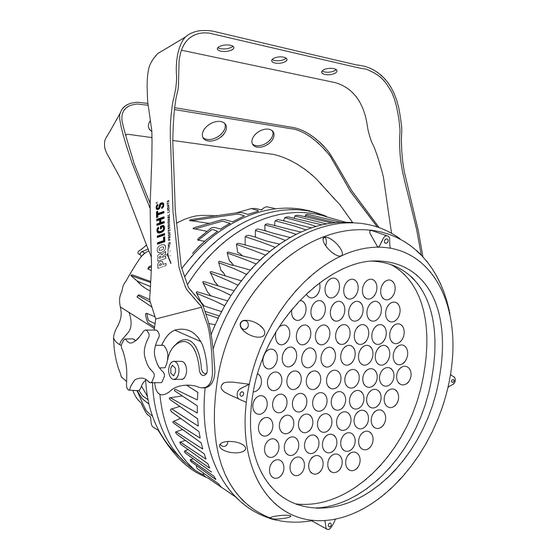
ARCLED7361ZOOM 1.3 ELEMENTI DI COMANDO E DI COLLEGAMENTI Fig.3 Vista Posteriore 1. STAFFA DI MONTAGGIO 2. MANOPOLA DI FISSAGGIO per la staffa di montaggio. 3. DMX OUT (XLR 3 poli): 1 = massa, 2 = DMX -, 3 = DMX + 4. -
Page 8: Installazione
- 2 - INSTALLAZIONE 2.1 MONTAGGIO ARCLED7361ZOOM può essere collocato su un piano solido. Inoltre, grazie alle possibilità di fissaggio sulla doppia staffa (fig.4), l’unità può essere montata anche a testa in giù, su una traversa. Per il fissaggio oc- corrono dei supporti robusti per il montaggio. -
Page 9: Funzioni E Impostazioni
- 3 - FUNZIONI E IMPOSTAZIONI 3.1 FUNZIONAMENTO Per accendere l’ ARCLED7361ZOOM, inserire la spina del cavo di alimentazione in una presa di rete (240V~ 50Hz). L’unità può essere comandata da un unità DMX di comando luce oppure svolgere autonomamente il suo programma. -
Page 10: Struttura Menu
ARCLED7361ZOOM 3.3 STRUTTURA MENU R.(0 - 255) STAT GREN G.(0 - 255) BLUE B.(0 - 255) WHIT W.(0 - 255) ZOOM Z.(0 - 255) STRB S.(0 - 020) AT.01 AUTO AT.02 AT.10 PR.01 PR.02 PR.10 SLAV D. (0-512) MENU TOUR PERS ARC.1... - Page 11 ARCLED7361ZOOM UPLD PASS **** SEND REST PASS **** REST COLOR RGBW DIM4 DIM3 DIM2 DIM1 DERR SAVE BLAK ZOOM POS1 POS2 BASE MENU **** WT.01 R.(0 - 255) WT.02 GREN G.(0 - 255) BLUE B.(0 - 255) WT.11 WHIT W.(0 -225) R.(0 - 255)
-
Page 12: Funzionamento In Modalità Automatica
• Sull’unità master selezionare il programma desiderato come indicato al paragrafo 3.4. • Servirsi dei connettori DMX dell’ ARCLED7361ZOOM e di un cavo XLR per formare una catena di unità. In certe condizioni e lunghezze si consiglia di effettuare una terminazione come mostrato a pagina 14. -
Page 13: Indirizzamento Dmx
DMX per il primo canale DMX. Se, per esempio, sull’unità di comando è previsto l’indirizzo 33 per comandare la funzione del primo canale DMX, si deve impostare sull’ ARCLED7361ZOOM l’indirizzo di start 33. Le altre funzioni del pannello saranno assegnate automaticamente agli indirizzi successivi. -
Page 14: Costruzione Del Terminatore Dmx
ARCLED7361ZOOM • Collegare l’uscita DMX del controller con l’ingresso DMX della prima unità; • Collegare, quindi, l’uscita DMX con l’ingresso DMX della successiva unità; l’uscita di quest’ultima con l’ingresso di quella successiva e via dicendo finchè tutte le unità sono collegate formando una catena. -
Page 15: Tabella Canali Dmx
ARCLED7361ZOOM 3.12 TABELLA CANALI DMX TOUR CH Function in TOUR mode Value CH Function in TOUR mode Value AUTO MASTER DIMMER 0 - 100% 000 - 255 No Function 000 - 020 RED 0 - 100% Auto 1 021 - 030 (or STEP TIME when CUS.01 - CUS.10 in CH.8... - Page 16 ARCLED7361ZOOM ARC.1 CH Function in ARC.1 mode Value RED 0 - 100% 000 - 255 GREEN 0 - 100% 000 - 255 BLUE 0 - 100% 000 - 255 AR1.D CH Function in AR1.D mode Value MASTER DIMMER 0 - 100%...
- Page 17 ARCLED7361ZOOM AR2.D CH Function in AR2.D mode Value MASTER DIMMER 0 - 100% 000 - 255 RED 0 - 100% 000 - 255 GREEN 0 - 100% 000 - 255 BLUE 0 - 100% 000 - 255 WHITE 0 - 100% 000 - 255 AR2.S...
-
Page 18: Istruzioni Di Base Configurazione Tour
ARCLED7361ZOOM 3.13 ISTRUZIONI DI BASE PER IL FUNZIONAMENTO DMX NELLA CONFIGURAZIONE TOUR Master dimmer • Il canale 1 controlla l’intensità di luce del proiettore. • Quando il cursore del controller è posizionato al valore massimo (255) l’intensità d’uscita è massima. -
Page 19: Funzioni Speciali
ARCLED7361ZOOM zione della scena [TIME] ed infine la dissolvenza [FADE]. • I valori (000 - 255) possono essere selezionati attraverso i tasti UP e DOWN. 3.16 FUNZIONI SPECIALI • Premere il tasto MENU e selezionare attraverso i tasti direzionali la voce [SET]; per confermare premere il tasto ENTER. -
Page 20: Funzione Password
ARCLED7361ZOOM 3.17 FUNZIONE PASSWORD Per attivare/disattivare la password di accesso: • Premere il tasto MENU fino a quando sul display non appare [KEY], quindi premere il tasto ENTER. • Selezionare [ON] oppure [OFF] a seconda che si voglia, rispettivamente, attivare o disattivare la password di accesso. -
Page 21: Manutenzione
ARCLED7361ZOOM - 4 - MANUTENZIONE 4.1 MANUTENZIONE E PULIZIA DEL SISTEMA OTTICO • Durante gli interventi, assicurarsi che l’area sotto il luogo di installazione sia libera da personale non qualificato. • Spegnere l’unità, scollegare il cavo di alimentazione ed aspettare finché l’unità non si sia raffreddata. -
Page 22: Appendice
ARCLED7361ZOOM - 5 - APPENDICE 5.1 VISTA ESPLOSA Fig.9 ITEM ITEM Head cover Power supply Rubber seal Connection board Clear glass Drive support Lens holder up Display PCB Zoom lens Button board Lens holder down Display lens Lens base Casing... - Page 25 3. 6 Linking 5. 1 Exploded view 3. 7 DMX configurations 3. 8 DMX Mode Warranty 3. 9 DMX addressing • ARCLED7361ZOOM Packing content • Safety cable • IP67 power extension cable • IP67 signal extension cable • Mount bracket (2 pc.) • User manual...
-
Page 26: General Instructions
ARCLED7361ZOOM WARNING! Before carrying out any operations with the unit, carefully read this instruction manual and keep it with cure for future reference. It contains important information about the installation, usage and maintenance of the unit. SAFETY General instruction • The products referred to in this manual conform to the European Community Directives and are therefore marked with • The unit is supplied with hazardous network voltage (230V~). -
Page 27: Introduction
- 1 - INTRODUCTION 1.1 DESCRIPTION ARCLED7361ZOOM is a unique LED luminaire in LED lighting range for its performance and technological contents. It has been conceived to innovate the concept of LED source applied to lighting sector, featuring the innovative zoom technology for a linear passage from 8° spot to 40° wide beam. - Page 28 ARCLED7361ZOOM • Double hanging bracket suitable for safe hanging and for floor positioning • Power unit: 100-240V 50/60Hz • Working temperatures: -40/45° • Power output to link more units in a chain: up to 12 fixtures at 230V • Max power consumption: 180W • Weight: 9 kg...
-
Page 29: Operating Elements And Connections
ARCLED7361ZOOM 1.3 OPERATING ELEMENTS AND CONNECTIONS Fig.3 Rear view 1. MOUNTING BRACKET 2. LOCKING KNOB for the mounting bracket. 3. DMX OUT ( 3-pole XLR): 1 = ground, 2 = DMX -, 3 = DMX + 4. DMX IN (3-pole XLR): 1 = ground, 2 = DMX -, 3 = DMX + 5. -
Page 30: Installation
- 2 - INSTALLATION 2.1 MOUNTING ARCLED7361ZOOM may be set up on a solid and even surface. The unit can also be mounted upside down to a cross arm. For fixing, stable mounting clips are required. The mounting place must be of sufficient stability and be able to support a weight of 10 times of the unit’s weight. -
Page 31: Functions And Settings
ARCLED7361ZOOM - 3 - FUNCTIONS AND SETTINGS 3.1 OPERATION Connect the supplied main cable to a socket (240 V~/50 Hz). Then the unit is ready for operation and can be operated via a DMX controller or it independently performs its show program in succession. To switch off, disconnect the mains plug from the socket. -
Page 32: Menu Structure
ARCLED7361ZOOM 3.3 MENU STRUCTURE R.(0 - 255) STAT GREN G.(0 - 255) BLUE B.(0 - 255) WHIT W.(0 - 255) ZOOM Z.(0 - 255) STRB S.(0 - 020) AT.01 AUTO AT.02 AT.10 PR.01 PR.02 PR.10 SLAV D. (0-512) MENU TOUR PERS ARC.1... - Page 33 ARCLED7361ZOOM UPLD PASS **** SEND REST PASS **** REST COLOR RGBW DIM4 DIM3 DIM2 DIM1 DERR SAVE BLAK ZOOM POS1 POS2 BASE MENU **** WT.01 R.(0 - 255) WT.02 GREN G.(0 - 255) BLUE B.(0 - 255) WT.11 WHIT W.(0 -225) R.(0 - 255)
-
Page 34: Operation In Automatic Mode
3.9 DMX CONTROL To able to operate the ARCLED7361ZOOM with a light controller, adjust the DMX start address for the first a DMX channel. If e. g. address 33 on the controller is provided for controlling the function of the first DMX channel, adjust the start address 33 on the ARCLED7361ZOOM. -
Page 35: Connection Of The Dmx Line
ARCLED7361ZOOM Number of Start address DMX Address Next possible start Next possible start Next possible start DMX channels (example) occupied address for unit No. 1 address for unit No. 2 address for unit No. 3 33-44 DMX Address: 33 DMX Address: 45... -
Page 36: Construction Of The Dmx Termination
ARCLED7361ZOOM 3.10 CONSTRUCTION OF THE DMX TERMINATION The termination avoids the risk of DMX 512 signals being reflected back along the cable when they reach- es the end of the line: under certain conditions and with certain cable lengths, this could cause them to cancel the original signals. -
Page 37: Dmx Control
ARCLED7361ZOOM 3.11 DMX CONTROL TOUR CH Function in TOUR mode Value CH Function in TOUR mode Value AUTO MASTER DIMMER 0 - 100% 000 - 255 No Function 000 - 020 RED 0 - 100% Auto 1 021 - 030 (or STEP TIME when CUS.01 - CUS.10 in CH.8... - Page 38 ARCLED7361ZOOM ARC.1 CH Function in ARC.1 mode Value RED 0 - 100% 000 - 255 GREEN 0 - 100% 000 - 255 BLUE 0 - 100% 000 - 255 AR1.D CH Function in AR1.D mode Value MASTER DIMMER 0 - 100%...
- Page 39 ARCLED7361ZOOM AR2.D CH Function in AR2.D mode Value MASTER DIMMER 0 - 100% 000 - 255 RED 0 - 100% 000 - 255 GREEN 0 - 100% 000 - 255 BLUE 0 - 100% 000 - 255 WHITE 0 - 100% 000 - 255 AR2.S...
-
Page 40: Basic Instructions For Tour Operation
ARCLED7361ZOOM 3.13 BASIC INSTRUCTIONS FOR DMX OPERATION (TOUR) Master dimmer • CH1 controls the intensity of the currently projected color. • When the slider is at the highest position (255) the intensity of the output is the maximum. Red, green, blue and white color selection •... -
Page 41: Special Functions
ARCLED7361ZOOM 3.16 SPECIAL FUNCTIONS • Press the button menu and select through the directional buttons the [SET] mode; and press the button ENTER to confirm. It is possible to view to following functions: UPLD • Select [UPLD] to upload the custom programs from the current Master unit to the Slave units. -
Page 42: Cal Function
ARCLED7361ZOOM 3.18 CAL FUNCTION When the user enter [CAL] and input the correct password, the hidden menu , will appear on display panel, and the user is able to reset the values of all functions. The default access code is UP + DOWN + UP + DOWN. -
Page 43: Maintenance
ARCLED7361ZOOM - 4 - MAINTENANCE 4.1 MAINTENANCE AND CLEANING THE UNIT • Make sure the area below the installation place is free from unwanted persons during setup. • Switch off the unit, unplug the main cable and wait until the unit has cooled down. -
Page 44: Appendix 5. 1 Exploded View
ARCLED7361ZOOM - 5 - APPENDIX 5.1 EXPLODED VIEW Fig.9 ITEM ITEM Head cover Power supply Rubber seal Connection board Clear glass Drive support Lens holder up Display PCB Zoom lens Button board Lens holder down Display lens Lens base Casing... - Page 45 Place Stamp Here Affrancare Spett.le Music&Lights S.r.l. Via Appia Km 136.200 04020 Itri (LT) Italy "...
- Page 48 Music & Lights S.r.l. entertainment technologies Via Appia km 136,200 - 04020 Itri (LT) ITALY ISO 9001:2008 tel. +39 0771 72190 fax +39 0771 721955 Certified Company www.musiclights.it info@musiclights.it...
Need help?
Do you have a question about the ARCLED7361ZOOM and is the answer not in the manual?
Questions and answers