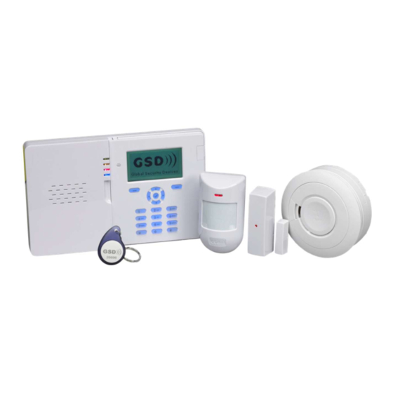
GSD i70 Installation Manual
Grade 2 wireless intruder alarm system
Hide thumbs
Also See for i70:
- User manual (8 pages) ,
- Installation manual (2 pages) ,
- User manual (2 pages)
Table of Contents
Advertisement
Quick Links
See also:
User Manual
Global Security Devices Ltd: No.3 Broomhill Business Complex, Tallaght,
Dublin 24, Ireland, Phone: +353 (1) 524 2691, Email: info@globalsecurity.ie
www.globalsecurity.ie
Contents
Installation Instructions
Operation Instructions
Trouble shooting
25
Technical Specification
31
Grade 2 Wireless Intruder Alarm System
Installation Manual
YOUR SECURITY IS OUR PRIORITY
2
8
i 70
V1.04
Advertisement
Table of Contents

Subscribe to Our Youtube Channel
Related Manuals for GSD i70


Summary of Contents for GSD i70
- Page 1 YOUR SECURITY IS OUR PRIORITY Contents Installation Instructions Operation Instructions Trouble shooting Technical Specification i 70 Grade 2 Wireless Intruder Alarm System Installation Manual Global Security Devices Ltd: No.3 Broomhill Business Complex, Tallaght, V1.04 Dublin 24, Ireland, Phone: +353 (1) 524 2691, Email: info@globalsecurity.ie www.globalsecurity.ie...
-
Page 2: Table Of Contents
Configure keypads (optional) Configure sirens (optional) Configure users Configure areas Configure timers Walk testing Output testing Soak testing (optional) Heat Carbon Monoxide Trouble shooting Detector Detector GSD i70 Panel Set up reporting (optional) Technical Specifications Menus / Wizards Panic Alarm Smoke Detector... - Page 3 Installation Diagrams Installation Diagrams Control Panel Opening Control Panel opening PA mounting 3: lift Cover 1 4: lift cover 2 upwards to upwards to remove before remove removing Cover 2 to remove cover pull to remove cover pull out on right and slide left out on right and slide left Cover 1 Cover 2...
- Page 4 Installation Diagrams Installation Diagrams Control Panel Mounting Control Panel Wiring Remove covers 1 & 2 and battery before mounting See instructions for Control Panel Opening and Remove cover 1 to access the wiring terminals. See instructions for Control Panel Opening for Battery Removal.
-
Page 5: Operation Instructions
Operation Instructions Operation Instructions Wiring External-Siren keypad features soft keys relating to on screen menu navigation and ok keys Supports third party Wired External Sirens alpha numeric keypad PQRS LED Status: Green LED: Solid = Battery fully charged, Flashing = Battery charging Amber LED: Fault Indication Red LED: Alarm Indication Blue LED: Solid = Full Set, Flashing = Part Set or some Areas Set... - Page 6 Operation Instructions Operation Instructions Restoring All Factory Default Settings Restoring All Factory Default Settings See control panel opening for removal battery terminal of covers to access the control panel PCB. IMPORTANT NOTICE mains PSU This should only be carried out when you want to completely default the terminal control panel back to its original default state as ALL programming of the system will be lost!
-
Page 7: Start The Installer Menu
Operation Instructions Operation Instructions Start the installer menu Menu Operation Start the installer menu: enter the installer code. Navigation - The keypad will display any faults that have occurred on the system, including Up / Down move in the current menu faults that occurred but are not currently present. - Page 8 Operation Instructions Operation Instructions Right move the cursor one character right or press and hold to move enter a space the cursor several characters Delete delete one character to the right of the cursor or press and Cancel cancel the change and revert to the unchanged account code hold to delete several characters store the new account code Left...
-
Page 9: Install Devices
Operation Instructions Operation Instructions Install Devices Enrol GSDi sensors onto the system, one per zone. GSD recommends that you Press Next. enrol each device at the location where it will operate as this facilitates - All devices end with a test showing the zone and tamper state of the device. -
Page 10: Configure Zones
Operation Instructions Operation Instructions Configure Zones LF alarm Indicates an external dialler Line Fault. Always causes an alarm (See also Menu Operation) whether its area is set or unset. Configure zones with sensors connected so that they function as required. Indicates an external dialler Failure To Communicate. -
Page 11: Configure Users
Operation Instructions Operation Instructions Configure Sirens ( optional ) Configure Areas Change individual siren options. Set the properties of each area. (See also Menu Operation) Select a siren menu: in the installer menu navigate to Sirens - <desired Select an area menu: in the installer menu navigate to Areas - <desired siren>... -
Page 12: Configure Timers
Operation Instructions Operation Instructions Configure Timers Walk Testing Program the System timers, Output timers and Area timers. Test all the sensors in each area are functioning correctly and communicating alarms to the system. Select the Walktest Outputs: in the installer menu navigate to Devices/Zones Select the system timers menu: in the installer menu navigate to Timers - System and then press OK. -
Page 13: Output Testing
Operation Instructions Operation Instructions Output Testing Troubleshooting Test correct functioning of all keypads, sirens, strobes and other outputs. Device fails to enrol Select the test outputs menu: in the installer menu navigate to System - - Device is a keypad and it fails to leave its current system: see Device fails Tools - Test outputs and then press OK. - Page 14 Operation Instructions Operation Instructions Device fails to enrol - cannot find system to enrol on Battey Voltages Either the system is not in enrol mode - see Install end devices for instructions All battery voltages can be viewed as follows. - or the device is out-of-range.
- Page 15 Operation Instructions Operation Instructions Set up reporting ( optional ) Set up Alarm Receiving Centre (ARC) details to report alarms, set/unset and Test call phone number 2: if you set phone number 2 then navigate out of faults as required. Connection 1 and into Connection 2 - Do test call and press OK.
-
Page 16: Technical Specifications
Operation Instructions Technical Specification Technical specification Change events reported* GSD i70 Change the events reported to a main ARC. Open the ARC settings: in the Name of manufacturer Global Security Devices Ltd installer menu navigate to Communications - Alarm Rx Centres - <desired... -
Page 17: Technical Specification
Technical Specification Technical Specification GSD i70 GSD i70 No. of devices 1 controller/keypad/siren ACE Type 0 - 4 sirens / external siren 1 - 71 sensors Non-volatile memory Static RAM with memory support battery: CR2032. Battery life 5 years. Settings required to comply All grades with EN50131. - Page 18 Operation Instructions Operation Instructions Installer menu Overview Installation Wizards & Tools...
- Page 19 Operation Instructions Operation Instructions Devices / Zones Timers & Areas...
- Page 20 Operation Instructions Operation Instructions Users, Sirens & Keypads Communications & Outputs...
Need help?
Do you have a question about the i70 and is the answer not in the manual?
Questions and answers