Advertisement
Table of Contents
- 1 Specification
- 2 Section 1 Precaution
- 3 Section 2 Specific Service Instructions
- 4 Switch Pwb
- 5 Section 3 Disassembly
- 6 Front Panel Assy
- 7 Roller Assy
- 8 Top Cover
- 9 Section 4 Adjustment
- 10 Running Mode
- 11 Initialize All
- 12 Region Change
- 13 Touch Panel Calibration
- 14 Section 5 Troubleshooting
- Download this manual
SERVICE MANUAL
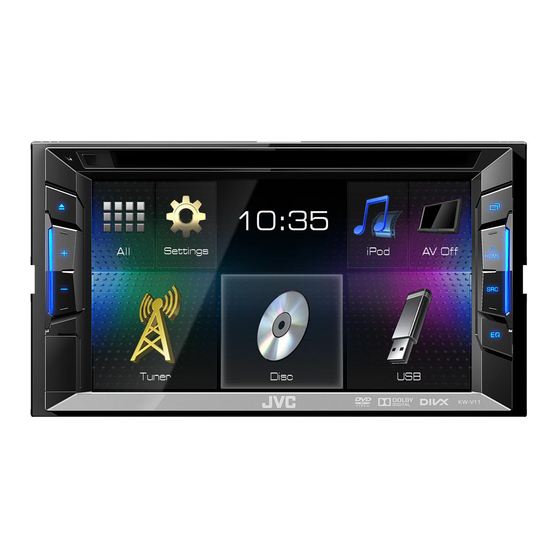
MONITOR WITH DVD RECEIVER
SERVICE MANUAL
10
2014
MA601<Rev.001>
KW-V11E, KW-V11EE, KW-V11EU, KW-V11J, KW-V11JW,
KW-V11U, KW-V11UI, KW-V215DBTE, KW-V21BTA,
KW-V21BTE, KW-V21BTEE, KW-V21BTEU, KW-V21BTJ,
KW-V21BTJW, KW-V21BTU, KW-V21BTUI
DC cord
DC cord
(QAM1561-001)
(QAM1562-001)
Escutcheon
Escutcheon
(B9H-0001-00)
(B9H-0002-00)
COPYRIGHT © 2014 JVC KENWOOD Corporation
Microphone
(QAN0137-001)
(3m)
Screw (M5x8)
(QYSTSP5008ZA) x6
Lead free solder used in the board (material: Sn-Ag-Cu, melting point: 219 Centigrade)
Lead free solder used in the board (material: Sn-Cu, melting point: 230 Centigrade)
COPYRIGHT © 2014 JVC KENWOOD Corporation
Mounting assy
Remote control
(J2C-0006-00)
(A7A-0006-00)
Screw (M5x8)
Lever
(QYSSSP5008ZA) x6
(D1A-0007-00) x2
Car cable
(QAM1419-001)
No.MA601<Rev.001>
2014/10
Advertisement
Table of Contents

Related Manuals for JVC KW-V11E


Summary of Contents for JVC KW-V11E
- Page 1 SERVICE MANUAL MONITOR WITH DVD RECEIVER MA601<Rev.001> 2014 SERVICE MANUAL KW-V11E, KW-V11EE, KW-V11EU, KW-V11J, KW-V11JW, KW-V11U, KW-V11UI, KW-V215DBTE, KW-V21BTA, KW-V21BTE, KW-V21BTEE, KW-V21BTEU, KW-V21BTJ, KW-V21BTJW, KW-V21BTU, KW-V21BTUI Microphone Mounting assy Car cable DC cord DC cord Remote control (QAN0137-001) (J2C-0006-00) (QAM1419-001)
-
Page 2: Specification
SPECIFICATION For US Monitor section Picture Size (W × H) 6.2 inches (diagonal) wide 137.5 mm × 77.2 mm (5-7/16" × 3-1/16") Display System Transparent TN LCD panel Drive System TFT active matrix system 1 152 000 (800H × 480V × RGB) Number of Pixels Effective Pixels 99.99%... - Page 3 FM tuner section Frequency Range With channel interval set to 200 kHz: 87.9 MHz to 107.9 MHz With channel interval set to 50 kHz 87.5 MHz to 108.0 MHz 7.2 dBf (0.63 µV/75 Ω) Usable Sensitivity (S/N: 30 dB Dev 22.5 kHz) 15.2 dBf (1.58 µV/75 Ω) Quieting Sensitivity (S/N: 46 dB Dev 22.5 kHz) Frequency Response (±...
- Page 4 SPECIFICATION For Europe Monitor section Picture Size (W × H) 6.2 inches (diagonal) wide 137.5 mm × 77.2 mm Display System Transparent TN LCD panel Drive System TFT active matrix system 1 152 000 (800H × 480V × RGB) Number of Pixels Effective Pixels 99.99% Pixel Arrangement...
- Page 5 Digital tuner (DAB) section (For KW-V215DBT) Frequency Range L-BAND: 1 452.960 MHz - 1 490.624 MHz BAND III: 174.928 MHz - 239.200 MHz Sensitivity -100 dBm Signal to Noise Ratio 90 Db DAB Aerial Connector Connector type: SMB Output Voltage: 14.4 V (11 V - 16 V allowable) Maximum Current: <100 mA FM tuner section Frequency Range (50 kHz)
- Page 6 SPECIFICATION For ASIA Monitor section Picture Size (W × H) 6.2 inches (diagonal) wide 137.5 mm × 77.2 mm Display System Transparent TN LCD panel Drive System TFT active matrix system 1 152 000 (800H × 480V × RGB) Number of Pixels Effective Pixels 99.99% Pixel Arrangement...
- Page 7 FM tuner section Frequency Range (50 kHz) 87.5 MHz to 108.0 MHz 6.2 dBf (0.56 µV/75 Ω) Usable Sensitivity (S/N: 30 dB Dev 22.5 kHz) 15.2 dBf (1.58 µV/75 Ω) Quieting Sensitivity (S/N: 46 dB Dev 22.5 kHz) Frequency Response (± 3.0 dB) 30 Hz - 15 kHz Signal to Noise Ratio 68 dB (MONO)
-
Page 8: Section 1 Precaution
SECTION 1 PRECAUTION Safety Precautions (1) This design of this product contains special hardware and Critical parts for safety many circuits and components specially for safety purpos- In regard with component parts appearing on the silk-screen es. For continued protection, no changes should be made printed side (parts side) of the PWB diagrams, the parts that are to the original design unless authorized in writing by the printed over with black such as the resistor (... - Page 9 Handling the traverse unit (optical pickup) (1) Do not subject the traverse unit (optical pickup) to strong shocks, as it is a sensitive, complex unit. (2) Cut off the shorted part of the flexible cable using nippers, etc. after replacing the optical pickup. For specific details, refer to the replacement procedure in the text.
- Page 10 Important for laser products 1.CLASS 1 LASER PRODUCT 5.CAUTION : If safety switches malfunction, the laser is able to function. 2.CAUTION : (For U.S.A.) Visible and/or invisible class II laser radiation 6.CAUTION : Use of controls, adjustments or performance of when open.
-
Page 11: Section 2 Specific Service Instructions
SECTION 2 SPECIFIC SERVICE INSTRUCTIONS How to repair a fuse pattern 2.1.1 Purpose of fuse pattern In order to prevent serious damage on the circuit, fuse pattern is prepared on the GND line of RCA Terminal. This damage may take due to improper part replacement with a external equipment via RCA line. 2.1.2 Repair Procedure (1) Check the shorted circuit at the meltdown point. -
Page 12: Switch Pwb
Ref. No. Application / Function Operation / Condition / Compatibility Ref. No. Application / Function Operation / Condition / Compatibility Transistor Parking control Q206 KEY_LED power control Transistor Parking control Q261 SW (KW-V only) KEY LED Constant current circuit Transistor Reverse control Q302 Voltage Drop... -
Page 13: Section 3 Disassembly
SECTION 3 DISASSEMBLY Main body 3.1.1 Removing the VIDEO PWB (See Fig.1 to 5) and CN801. (1) Remove the 1 screw A. (See Fig.1) (4) Disconnect the wires from CN201 (See Fig.4) CN201 CN801 Fig.4 (5) Disconnect the wires from CN202, CN203, CN301, CN401 and CN402. - Page 14 3.1.2 Removing the SWITCH PWB. (See Fig.6 and 7) (3) Remove the 2 screws M, and remove the TOP PLATE. (1) Remove the 2 screws F and 1 screw G, and remove the (See Fig.9) BRACKET. (See Fig.6) BRACKET Fig.6 (2) Remove the 4 screws H, and remove the GUIDE(L/R).
- Page 15 3.1.4 Removing the MAIN PWB (See Fig.12 to 14) 3.1.5 Removing the DAUGHTER PWB (See Fig.15) (1) Remove the 2 screws P and 1 screw Q. (See Fig.12) (1) Disconnect the FFC wire from CN501. (2) Remove the 2 screws T, and remove the DAUGHTER PWB.
-
Page 16: Roller Assy
DVD mechanism assembly (3) Remove the 1 screw C, and remove the ROLLER ASSY. (See Fig.4) 3.2.1 Removing the DVD MECHA PWB (See Fig.1) (1) Solder the short land on the PICK UP. (2) Disconnect the FPC or Connector wires from CN101, CN201, CN202 and CN301. -
Page 17: Section 4 Adjustment
SECTION 4 ADJUSTMENT Test Mode 4.1.1 List of special modes Mode name Description Key used TUNER span switching Switches TUNER frequency step/span. Press and hold the [DISP] key and [EJECT] key, and press the [RESET] key. Memory clear Clears the backup memory and installer memory. INITIALIZE inside the Setup menu (INITIALIZE in the service mode) SS mode... - Page 18 Service Mode Page2 Text Description DATA4 **** Display of DEMO image version (Commercially=”1000”) DAB ****/******** Display of DAB module version HDR ******** Display of HD-Radio module version 4.2.2.1 INITIALIZE ALL Process (1) to (4) in sequence. (1) Initialization of system controller EEPROM Backup memory, user profiles 1 to 3 Tuner Area setting Error history...
-
Page 19: Running Mode
<When INITIALIZE terminated abnormally> 4.2.2.3 RUNNING MODE DVD MODE5: Displays the currently selected mode COUNT: Counter display DVD ERROR: Displays the error code for error in the DISC mecha (display as 000000 when there is no error) DOOR ERROR: Displays the error code for error in the door mecha (display as 000000 when there is no error) *Immediately after moving to the RUNNING MODE, hide the dis- play of all the above. - Page 20 4.2.2.4 DVD CHECK MODE (6) DVDx1 JITTER MODE When this mode is selected, reset DISC module and restart in Process test item [6] of the check mode specification Check Mode. (Specify "Check Mode On" in the startup mode for 2nd line display: DVDx1 JITTER MODE 0x94 command.) 3rd line display: Display Arg 2,3,4,5 (HEX) of the command After restarting in Check Mode, transit to DVD CHECK MODE...
- Page 21 4.2.2.5 ERROR/DIAG DATA 4.2.2.9 BT MICROPHONE TEST The mode for confirming the normal operation of BT audio circuit by inputting audio from MIC and outputting from the speaker. • Switch the audio selector to Bluetooth. • Send Bluetooth Loop back START command to TCC. •...
- Page 22 4.2.2.10 FIRM UPDATE MODE 4.2.2.11 STEERING REMOTE DEVELOPMENT [BACK] key: Goes back to the Service Mode [BACK] key: Goes back to the Service Mode (1) [Bluetooth]/[APPCOM]/[SYSCOM]/[DAB] key 4.2.2.12 SXM CODE CLR Perform Update when a USB device containing the Update Mode for clearing the Sirius XM parental code data is inserted.
- Page 23 SS mode SS Mode Page3 4.3.1 Switching to SS mode Press and hold the [EQ] key and [DISP] key (1), and press the [RESET] key (2). [NEXT] key: Switch from Page 1 → Page 2. [PREV] key: Switch from Page 2 → Page 1. [EXIT] key: Exit the SS Mode and return to the normal screen.
-
Page 24: Initialize All
4.3.3.1 INITIALIZE ALL Text Description Same as service mode. TOU: Y or N Display of status of touch panel adjustment 4.3.3.2 S/N WRITE & RGB(SXM) TERMINAL CHK by production line. Mode for entering the serial number. Y: adjustment complete *This will not be displayed for models without the NAVI and Sxi N: not adjusted. -
Page 25: Region Change
4.3.3.5 REGION CHANGE (4) Display the following when the update is failed. The mode for rewriting a Region Code. Download the rewriting data from CUSiS. • Extracts zip file. • Find Vup_info.cds and ZZZ files. • Write the 2 files to root of USB MEMORY. (1) Display the following if the USB device is inserted when this mode is selected. -
Page 26: Touch Panel Calibration
4.3.3.7 TOUCH PANEL CALIBRATION 4.3.3.8 VER/CHECK SUM Define the coordinates used in this sheet. Performs check on the version number of each micro-controller/ data and the SUM value of the APP program area/DATA area. Select this item after inserting a USB device containing the check data for all of the above. - Page 27 Line Data Content Description 10 [DATA4]1000 DATA3 version No. (DEMO image data) 11 [SYS]3.000 SYSCOM version No. 12 [DISC_A]JC DISC mecha destination code. Rewritten according to the shipment destination. 13 [DISC_R]1 DISC mecha region No. Rewritten according to the shipment destination. (4) When USB device is not inserted 14 [DISC_V]0010 DISC mecha version No.
- Page 28 4.3.3.10 Sirius XM CHECK MODE DC Offset error description Mode for check of Sirius XM terminals. 4.4.1 DC Offset detection circuit design By using the audio output from the internal oscillator of SXV100, • Purpose: it is possible to check all of the power lines / communication lines To prevent breakdown, when occur DC offset between speak- / audio line.
-
Page 29: Section 5 Troubleshooting
4.4.5 Manipulate after detect DC Offset • If judge as "Capacitor leak ". • If detected error 10 consecutive times, and 10th error occurred - turn off speaker output. in "Mis-connect detection period", judge as "Mis-connect". - display "WIRING", check wiring connection then reset. •... - Page 30 JVC KENWOOD Corporation CE Segment 2967-3, Ishikawa-machi, Hachioji-shi, Tokyo, 192-8525, Japan (No.MA601<Rev.001>) Printed in Japan...
Need help?
Do you have a question about the KW-V11E and is the answer not in the manual?
Questions and answers