Advertisement
Advertisement

Related Manuals for Bush AG96RW


Summary of Contents for Bush AG96RW
-
Page 2: Table Of Contents
Techical Specifications Before using your appliance carefully read this guide as it includes basic information for correct and safe installation, maintenance and use. Contact your nearest authorised service agent for installation of your appliance. DESCRIPTION OF THE OVEN Product code AG96RW... -
Page 3: Parts
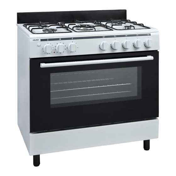
Parts Customer Helpline 0345 257 7271 Please familiarise yourself with the parts and accessories listed below 1- Splashback 10- Oven Burner 2- Cooktop 11- Auxillary Burner 3- Control Panel 12- Rapid Burner 4- Oven Door Handle 13- Semi-Rapid Burner 5- Drawer Cover 14- Pan Support 6- Adjustable Feet 15- Wok Burner... -
Page 4: Safety Information
Safety Information Customer Helpline 0345 257 7271 Important - Please read these instructions fully before installation READ THESE INSTRUCTIONS CAREFULLY AND WARNING- Danger of fire: do not COMPLETELY BEFORE USING YOUR store items on the cooking surfaces. APPLIANCE, AND KEEP IT IN A CONVENIENT PLACE FOR REFERENCE WHEN NECESSARY. - Page 5 Safety Information Customer Helpline 0345 257 7271 Important - Please read these instructions fully before installation damage to the surface. IMPORTANT- If after 15 s the burner has not lit, stop operating the device and open the IMPORTANT- Do not use steam compartment door and/or wait at least 1 min before attempting a further ignition of the burner.
- Page 6 Safety Information Customer Helpline 0345 257 7271 Important - Please read these instructions fully before installation appliance (cabinet) must be able to withstand a ventilation holes open or install a mechanical temperature of min 100°C. ventilation device (mechanical extractor hood). During usage IMPORTANT- Prolonged intensive use of the appliance may call for additional ventilation, for...
-
Page 7: Installation
Installation Customer Helpline 0345 257 7271 Cooker hood This modern, functional and practical cooker, that Electrical ventilator flue was manufactured with parts and materials of the Air inlet section Air inlet section highest quality and will meet your cooking needs in min. - Page 8 Installation Customer Helpline 0345 257 7271 • If the kitchen furniture are higher than the fluids. No bubble should appear. If there are cooktop, it must be at least 10cm away from bubbles, check the connection joint and redo the the cooker's side.
- Page 9 Installation Customer Helpline 0345 257 7271 Gas conversion Caution : The following procedures must be undertaken by authorized service people. Your appliance is adjusted to be operated with LPG/NG gas. The gas burners can be adapted to different types of gas, by replacing the corresponding injectors and adjusting the minimum flame length, suitable to the gas in use.
- Page 10 Installation Customer Helpline 0345 257 7271 Figure 9.1 Figure 9.2 Figure 9.3 Figure 9.4 Figure 9.5 Figure 9.6 Adjusting the reduced flame position Valve with flame failure device The flame length in the minimum position is adjusted with a flat screw located on the valve. For valves with flame failure device, the screw is located on the side of the valve spindle.
- Page 11 Installation Customer Helpline 0345 257 7271 Electric connection and safety (If available) During the electric connection, follow the instructions stated in the user manual • The earthing cable must be connected to the earth terminal • You have to ensure the power cord with suitable insulation to be connected to the power source during the connection If there is no appropriate earthed electric outlet in...
-
Page 12: User Instructions
User Instructions Customer Helpline 0345 257 7271 Control Panel 5- Gas Hob Kontrol Knob-Front Left 1- Oven Lamp Button 6- Gas Hob Kontrol Knob-Rear Left 2- Timer 7- Gas Hob Kontrol Knob-Middle 3- Oven control knob 8- Gas Hob Kontrol Knob-Rear Right 4- Ignition Button 9- Gas Hob Kontrol Knob-Front Right... - Page 13 User Instructions Customer Helpline 0345 257 7271 Use of gas burners Ignition of the burners To determine which knob controls which burner, check the position symbol above the knob. • Manual Ignition of the Gas Burners If your appliance is not equipped with any ignition aid or in case there is a failure in the electric network, follow the procedures listed below For Hob Burners: To ignite one of the burners,...
- Page 14 User Instructions Customer Helpline 0345 257 7271 Flame safety device: Hob Burners Hobs equipped with a flame failure device provide security in case of accidentally extinguished flames. If such a case occurs, the device will block the burners gas lines and will avoid any accumulation of unburned gas.
- Page 15 User Instructions Customer Helpline 0345 257 7271 Your hob has burners of different diameters. The most economic way of using gas is to choose the correct size gas burners for your cooking pan size and to bring the flame to minimum position once the boiling point is reached.
- Page 16 User Instructions Customer Helpline 0345 257 7271 Control of the Oven Burner 90x60 After you ignite the oven burner as explained POSITION TEMPERATURE before, you can adjust the temperature inside the MAX. 280 C oven as you require, using the numbers on the 240 C control panel or knob ring: Bigger numbers mean 230 C...
- Page 17 Align the bushes with the assembly slots so that the shield is stuck between the control panel and the bush. Push the shield towards the appliance until it is firmly in its place.
- Page 18 User Instructions Customer Helpline 0345 257 7271 Use of mechanical minute minder Set the desired cooking time by turning the timer button clockwise. At the end of this time period, it will make a beep sound, but the oven continues working.
- Page 19 User Instructions Customer Helpline 0345 257 7271 Accessories Oven Cavity • The product already supplied with accessories. You can also use accessories you purchase Rack positions from the market, but they must be heat and flame resistant. You can also use glass dishes, cake molds and special oven trays that are 5.
-
Page 20: Cleaning And Maintenance
Cleaning And Maintenance Customer Helpline 0345 257 7271 Cleaning Be sure that all control switches are off and your appliance cooled before cleaning your oven. Plug off the appliance. Check whether they are appropriate and recommended by the manufacturer before using the cleaning materials on your oven. - Page 21 Cleaning And Maintenance Customer Helpline 0345 257 7271 Removal of oven door To remove the oven door; • Open the oven door(1). • Open the saddle bracket (with aid of screwdriver, tongs etc.) up to end position(2). • Close the door till it almost reaches the full closed position as shown in 3 figure and remove the door by Saddle pulling it towards yourself.
- Page 22 Cleaning And Maintenance Customer Helpline 0345 257 7271 Maintenance Changing the Oven Lamp The product should first be switched off from the electricity supply and cool (not been used recently). Remove the glass lens, and then the bulb itself. Place new bulb into the socket (resistant to 300 (degrees) 230V, 25 Watt, Type E14).
-
Page 23: Service And Transport
Service and transport Customer Helpline 0345 257 7271 Basic troubleshooting before contacting service Information related to transport If you need any transport; keep the original case of If the oven does not operate : product and carry it with its original case when •... -
Page 24: Injector Table
Injector Table Customer Helpline 0345 257 7271 G30 28-30mbar 14.9 kW 1083 g/h G30/G31 II2H3+ GB Clase: 1 G20 20 mbar 28-30/37 mbar LARGE BURNER DIA. of INJECTOR (1/100mm) NOMINAL RATING (KW) CONSUMPTION 276,2 l/h 210,9 g/h MEDIUM BURNER DIA. of INJECTOR (1/100mm) NOMINAL RATING (KW) 1,75 1,65... -
Page 25: Technical Specifications
Technical Specifications Customer Helpline 0345 257 7271 AG96RW Model/Item Power supply (230)V Maximum power 25 W Size(H x W x D) 900x600x900/850 mm Net weight 65 kg. Oven Volume 100 lt. We apologise for any inconvenience caused by minor inconsistencies in these instructions that may occur as a result of product improvements and development.
Need help?
Do you have a question about the AG96RW and is the answer not in the manual?
Questions and answers