
Related Manuals for Yardworks 054-5753-0


Summary of Contents for Yardworks 054-5753-0
- Page 1 ELECTRIC CHAINSAW 054-5753-0 Owner's Manual TOLL-FREE HELPLINE: 1-866-523-5218 WARNING WARNING Read all safety rules and instructions carefully before operating this tool.
- Page 2 CONTENTS INTRODUCTION........................... GENERAL SAFETY RULES...................... SYMBOLS..........................DIAGRAM AND LOCATION OF PARTS................10-11 KNOW YOUR CHAINSAW..................... 12-13 ASSEMBLY..........................OPERATION ........................15-26 MAINTENANCE........................27-36 TROUBLESHOOTING........................ WARRANTY..........................EXPLODED VIEW........................39-40 PARTS LIST...........................41-42 PRODUCT SPECIFICATIONS ELECTRIC CHAINSAW Motor ..................120 V AC, 60 Hz, 9.0 Amp Horsepower ......................
- Page 6 GENERAL SAFETY RULES (See Figures 1 - 2.) KICKBACK WARNING: The following precautions should be followed to minimize kickback: ROTATIONAL KICKBACK KICKBACK DANGER ZONE Fig. 1 Fig. 2...
- Page 7 GENERAL SAFETY RULES (See Figure 3.) PULL PUSH Fig. 3...
- Page 8 SYMBOLS Some of the following symbols may be used on this product. Please study them and learn their meaning. Proper interpretation of these symbols will allow you to operate the product better and safer. SYMBOL NAME DESIGNATION/EXPLANATION Volts Voltage Amperes Current Hertz Frequency (cycles per second)
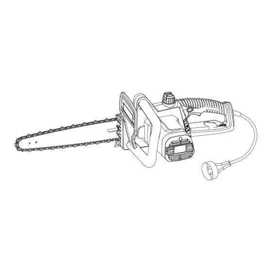
- Page 12 KNOW YOUR CHAINSAW FRONT HANDLE TRIGGER SWITCH SCABBARD LOW-KICKBACK SAW CHAIN OIL RESERVOIR FRONT HAND GUARD GUIDE REAR HANDLE CHAIN COVER CHAIN TENSIONING KNOB CHAIN COVER LOCK KNOB Fig. 5...
- Page 15 OPERATION WARNING: WARNING: Failure to do so could result in objects bein WARNING: APPLICATIONS You can use this product for the purposes listed below: ADDING BAR AND CHAIN LUBRICANT (See Figure 6) ired. NOTE: and refilled as needed. ank. eck and fill the oil tank when iew oil indicator is below the MIN.
- Page 16 OPERATION CONNECTING TO POWER SUPPLY (See Figure 7) This chainsaw is designed with a cord retainer that prevents the extension cord from being pulled loose while using. he opening in the side of the rear handle, and place over cord hitch. slack is removed.
- Page 17 PERAT (See Figure 8) START NG AN ST PP NG THE HA NSA ARN NG Keep body to the left of the chain line. Never straddle the saw or chain, or lean over past the chain line. to the chain cover. contact with the bar and chain.
- Page 18 OPERATION PREPARING FOR CUTTING PROPER GRIP ON HANDLES (See Figure 9) See General Safety Rules for appropriate safety equipment. rotection. cause loss of control. WARNING: PROPER HAND GRIP POSITION Fig. 9 WARNING: CHAIN LINE...
- Page 19 OPERATION PROPER CUTTING STANCE (See Figure 10) BASIC OPERATING/CUTTING PROCEDURES STRAIGHT THUM B ON CHAIN LINE UNDERSIDE OF HANDLE BAR Fig. 10...
- Page 23 OPERATION REMOVING BUTTRESS ROOTS (See Figure A buttress root is a large root extending from the trunk of the tree above the ground. Remove large buttress roots prior to felling. Make the horizontal cut into the buttress first, followed by the vertical cut.
- Page 24 OPERATION BUCKING WITH A WEDGE (See Figure 16) If the wood diameter is large enough for you to insert a soft bucking wedge without touching the chain, you should use the wedge to hold the cut open to prevent pinching. BUCKING LOGS UNDER STRESS (See Figure 17) Make the first bucking cut 1/3 of the way through the log, and finish with a 2/3 cut on the opposite side.
- Page 27 MAINTENANCE WARNING: When servicing, use only identical YARDWORKS replacement parts. Use of any other parts may create a hazard or cause product damage. WARNING: Always wear safety goggles or safety glasses with side shields during power tool operation or when blowing dust. If operation is dusty, also wear a dust mask.
- Page 28 MAINTENANCE Note: When replacing the guide bar and chain always use the specified bar and chain in the Bar and Chain combinations section later in this manual. MOUNTING SURFACE CHAIN CHAIN COVER LOCK KNOB CHAIN CHAIN CHAIN COVER CHAIN LOCK KNOB TENSIONING COVER TENSIONING...
- Page 29 MAINTENANCE NOTE: NOTE: CUTTERS CHAIN ROTATION CHAIN DRIVE LINKS Fig. 28 Fig. 26 GROOVE CHAIN DRIVE LINKS Fig. 27 Fig. 29...
- Page 30 MAINTENANCE NOTE:...
- Page 31 MAINTENANCE WARNING: ADJUSTING THE CHAIN TENSION (See Figure 30-31) NOTE: NOTE: NOTE: CAUTION: FLATS ON DRIVE LINKS Fig. 30 1/16" (1.3 mm) Fig. 31...
- Page 32 MAINTENANCE CAUTION: Make sure the chainsaw is disconnected from the power supply before you work on the saw. CHAIN MAINTENANCE (See Figure 32) Use only a low-kickback chain on this saw. This fast-cutting chain provides kickback reduction when properly maintained. For smooth and fast cutting, maintain the chain properly.The chain requires sharpening when the wood chips are small and powdery, the chain must be forced through the wood during cutting, or the chain cuts to one side.
- Page 33 MAINTENANCE SHARPENING THE CUTTERS (See Figure 33-36) Be careful to file all cutters to the specified angles and to the same length, because fast cutting can only be obtained when all cutters are uniform. CAUTION: saw. WARNING: Use a 5/32" (4 mm) diameter round file and holder. Do all of your filing at the midpoint of the bar. CUTTING CORNER SIDE PLATE...
- Page 35 MAINTENANCE MAINTAINING DEPTH GAUGE CLEARANCE MAINTAINING THE GUIDE BAR (See Figure 37) CAUTION: LUBRICATING HOLE Fig. 37...
- Page 39 EXPLODED VIEW...
- Page 40 PARTS LIST ITEM # PART NO. DESCRIPTION 34102324 Knob board 32210405 Bolts 34103324 Tension knob Side cover 34101324 33901405 Tension wheels 33310405 Tension knob borad 31130405 Chain 3290875 Washers 33302324 33302102 Washers 33902102 Chain wheel 3220504 Bolts 31104405-2 Right housing assembly 31102324 Oil tank 31105403...
- Page 41 PARTS LIST ITEM # PART NO. DESCRIPTION 32209405 Oil tube spring 32209302 Screw Bar pitch 33312405 3221675A Screw ST3*12-C Bolt 32208405 34104324 Scabbard 31111405 Rotor assembly Washer 34111405 31103405 Gear down box under cover...
Need help?
Do you have a question about the 054-5753-0 and is the answer not in the manual?
Questions and answers