Table of Contents
Advertisement
This manual is prepared for the use of Service Technicians
and should not be used by those not properly qualified.
This manual is not intended to be all encompassing. You
should read, in its entirety, the repair procedure you wish
to perform to determine if you have the necessary tools,
Instruments and skills
RETAIN THIS MANUAL FOR FUTURE REFERENCE.
The MONTAGUE Company
1830 Stearman Ave. • P.O.Box 4954 • Hayward, CA 94540-4954
Tel: 510/785-8822
Fax: 510/786-9931
1-888-875-2722
WWW.MONTAGUECOMPANY.COM
NOTICE
required to perform the procedure.
required
1
Advertisement
Table of Contents

Related Manuals for MONTAGUE Legend 12

Summary of Contents for MONTAGUE Legend 12
- Page 1 Instruments and skills required to perform the procedure. required RETAIN THIS MANUAL FOR FUTURE REFERENCE. The MONTAGUE Company 1830 Stearman Ave. • P.O.Box 4954 • Hayward, CA 94540-4954 Tel: 510/785-8822 Fax: 510/786-9931 1-888-875-2722...
-
Page 2: Important For Your Safety
IMPORTANT FOR YOUR SAFETY THIS MANUAL HAS BEEN PREPARED FOR PERSONNEL QUALIFIED TO INSTALL GAS EQUIPMENT, WHO SHOULD PERFORM THE INITIAL FIELD START-UP AND ADJUSTMENTS OF THE EQUIPMENT COVERED BY THIS MANUAL. POST IN A PROMINENT LOCATION THE INSTRUCTIONS TO BE FOLLOWED IN THE EVENT THE SMELL OF GAS IS DETECTED. -
Page 3: Shipping Damage Claim Procedure
IMPORTANT SHIPPING DAMAGE CLAIM PROCEDURE: For your protection, please note that equipment in this shipment was carefully inspected and packed by skilled personnel before leaving the factory. The transportation company assumed full responsibility for safe delivery upon acceptance of this shipment. IF SHIPMENT ARRIVES DAMAGED: 1. -
Page 4: Manifold Pressure
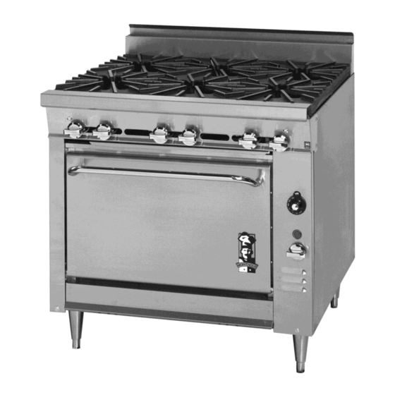
INTRODUCTION GENERAL The Montague heavy duty ranges are produced The gas fired heavy duty ranges covered in this with the best possible material and workmanship. manual are manufactured for use with the type Proper installation is essential for safe, efficient of gas indicated on the nameplate. -
Page 5: Installation
INSTALLATION THE INSTALLATION INSTRUCTIONS CONTAINED HEREIN ARE FOR THE USE OF QUALIFIED INSTALLATION AND SERVICE PERSONNEL ONLY. INSTALLATION OR SERVICE BY OTHER THAN QUALIFIED PERSONNEL MAY RESULT IN DAMAGE TO THE RANGE AND/ OR INJURY TO THE OPERATOR. Qualified installation personnel are individuals, a firm, corporation or company which either in person or through a representative are engaged in, and are responsible for: A. -
Page 6: Ventilating Hood
CAUTION Information on construction and installation of ventilating hoods may be obtained from the Provisions must made assure ―Standard for the Installation of Equipment for adequate air supply to unit for proper burner the Removal of Smoke and Grease Laden operation. - Page 7 Fry Top Ranges Adjust as follows: Fry Top Plate Adjustment: Leveling bolts are at FLOOR Adjust by turning the rear of the range under the fry top plate. Foot on adjustable leg. INSTALLATION ON LEGS Adjust the leveling bolts so that the plate is pitched to the front to provide for grease runoff as CURB Place shim under the low...
-
Page 8: Natural Gas
GAS APPLIANCE REGULATOR ote: At the time of installation, a gas appliance Unless the manifold pressure on all pressure regulator suitable for the battery connected appliances is the same, a separate application and adjusted for the manifold pressure regulator must be supplied for each pressure specified on the range nameplate must appliance with a different manifold pressure. -
Page 9: Gas Connection
GAS CONNECTION Install the gas pressure regulator with gas flowing as indicated by the arrow on the regulator. The arrow must be pointing toward the NOTE: Pipe joint compound or thread sealant unit. Using pipe compound or thread sealant, that is used should be resistant to action of carefully thread regulator to pipe so that there is liquefied petroleum gases. -
Page 10: Electrical Connection
ELECTRICAL CONNECTION lll. 220 VAC - 50 Hz - SINGLE PHASE Unless otherwise specified, the range is (2 WIRE) equipped with a 6 ft. flexible supply cord for 115 VAC, 60 or 50 Hertz, single phase units. The Follow steps outlined in ( ll. ) Refer to wiring wiring diagram is located on the back of the diagram for proper connection. -
Page 11: Burner Adjustment
PILOT ADJUSTMENT - TOP BURNERS FRY TOP & OVEN THERMOSTATS OPEN TOP: The front and rear pilots are The bypass (minimum burner flame) must be controlled by one valve. To adjust pilot, turn checked when performing checkout of range adjusting screw counter-clockwise to increase or prior to placing equipment in service. -
Page 12: Operation
OPERATION GENERAL GAS CONTROLS This appliance been classified WARNING commercial cooking equipment and must be operated qualified and/or professional IN THE EVENT A GAS ODOR IS DETECTED, personnel. SHUT DOWN UNITS AT MAIN SHUT OFF VALVE AND CONTACT THE LOCAL GAS COMPANY SUPPLIER WARNING... -
Page 13: Oven Operation
3. After pilot burner ignites, continue to hold red 5. If the pilot burner is unable to be lit with the button depressed for 30 to 45 seconds or Piezo Igniter, apply a lighted match to the until pilot remains burning when button is pilot burner. -
Page 14: Operating Controls
REF # CONTROL FUNCTION Operation is not difficult to understand or control. Three position rocker The Montague convection oven is a ―Muffled‖ switch: FAN/OFF/ style oven that keeps the by-product of COOL. combustion separated from the air circulated in the oven. The heat surrounding the oven cavity... - Page 15 SUGGESTIONS Lighting It is not necessary to turn on all equipment 1. Turn oven burner valve clockwise to ―OFF‖ first thing in the morning. Turn on only the position. equipment needed to begin the day and 2. Open main shutoff valve in the rear of the leave equipment off until it is needed.
-
Page 16: Maintenance
MAINTENANCE NEVER WIRE BRUSH, STEEL CAUTION SCOURING PADS ( EXCEPT STAINLESS ), SCRAPER, FILE, OR OTHER STEEL TOOLS. DISCONNECT POWER BEFORE CLEANING Surfaces which are marred collect dirt more OR SERVICING. EACH OVEN SECTION HAS rapidly and become more difficult to clean. SEPARATE ELECTRICAL SUPPLY... -
Page 17: Electric Motor
WEEKLY: Open Top Section should be washed The motor is of an open drip-proof type in a solution of washing soda and water (after construction, and as such, care should be taken they are entirely cooled) Remove and wash drip to see that the ventilation openings remain clear. -
Page 18: Maintenance Schedule
MAINTENANCE SCHEDULE COMPONENTS APRIL JUNE JULY AUG SEPT BLOWER WHEEL TOP BURNERS BURNER GRATES BURNER VALVES DOOR SWITCHS MOTOR TOP BURNER PILOTS OVEN PILOT ROCKER SWITCHES SAFETY VALVE THERMOCOUPLE THERMOSTAT GREASE CONTAINER AIR MIXERS 1. CHECK 2. CLEAN 3. ADJUST 4. -
Page 19: Oven Pilot Burner
SERVICE IMPORTANT NOTE: When servicing a unit with a defective pilot safety valve, the whole valve should be WHEN SERVICE IS NEEDED, CONTACT A replaced instead of just the magnetic head. LOCAL SERVICE COMPANY, DEALER, OR FACTORY PERFORM MECHANICAL OVEN PILOT BURNER MAINTENANCE REPAIRS. - Page 20 Pilot flame should surround approximately 1/2‖ of the thermocouple. If flame burns yellow, replace pilot orifice. Correct gas pressure is important to maintain proper size pilot flame. When accessing pilot through oven bottom liner on a V series oven, reseal bottom liner with furnace cement to prevent pilot outages.
-
Page 21: Gas Pressure Regulator
REMOVAL OF OVEN BURNER AND GAS PRESSURE REGULATOR PILOT BURNER WARNING: UNTRAINED PERSON SHOULD ATTEMPT MAINTAIN CAUTION: SERVICE THE GAS PRESSURE REGULA- TOR. TURN OFF GAS AT MANUAL SHUT OFF VALVE NEXT TO THE APPLIANCE BEFORE REMOVAL OF THE FLAME BAFFLE AND ATTEMPTING TO LOOSEN ANY GAS HEAT BAFFLE ASSEMBLY CONNECTIONS. -
Page 22: Thermostat Installation
CAUTION THERMOSTAT INSTALLATION OVERTIGTENING MAY CAUSE DAMAGE TO With front of the griddle raised, slide the THE THERMOCOUPLE OR MAGNET AND IS thermostat bulb assembly into the support UNNECESSARY SINCE THIS brackets attached to the underside of the fry top ELECTRICAL CONNECTION. - Page 23 Special care should be taken to see that the NOTE: If the bypass is not set correctly, it will thermostat bulb is in its proper place and no part affect the set temperature. of the capillary tube is in any flame or heat zone. The fry top plate should never be removed FRY TOP THERMOSTAT CALIBRATION without first removing the thermostat bulb(s)
- Page 24 THERMOSTAT CALIBRATION CHECK CAUTION 136 SERIES THE RECALIBRATION SHOULD NOT BE 1. Place the thermocouple of test instrument or MADE UNTIL BYPASS (MINIMUM thermometer in the middle of the oven. BURNER) FLAME HAS BEEN PROPERLY 2. Light the mail burner. ADJUSTED.
- Page 25 OVEN THERMOSTAT - 124 SERIES The Model BJ Robertshaw is a combination thermostat and gas valve. The gas is turned on and the temperature setting made by a single rotation of the dial. This valve automatically locks itself in the OFF position. To use, push inward, rotate counterclockwise to the desired temperature.
- Page 26 OVEN THERMOSTAT CALIBRATION CHECK OVEN BURNER FAILS TO COME ON 124 SERIES (PILOT ON): NOTE: The oven temperature should be 1. Burner valve off. checked or recalibrated with oven hot. 2. Burner orifice plugged. 3. Thermostat out of calibration. NOTE: See ―Adjustment of Bypass (Minimum 4.
- Page 27 CAUTION Motor Removal from the Mounting Plate: BEFORE REPLACING OVEN INTERIOR Remove four nuts from motor mounting bolts LINER BOTTOM, SEAL THE SIDE AND and remove motor. REAR FLANGES WITH FURNACE CEMENT TO PREVENT AIR LEAKS INTO COMBUS- To reassemble, reverse the above procedure. TION CHAMBER.
-
Page 28: Door Switch
IMPORTANT: WHEN INSTALLING BLOWER WHEEL ON MOTOR SHAFT, POSITION BLOWER WHEEL SO THAT IT WILL NOT RUB AGAINST BOLT HEADS ON MOUNTING PLATE OR CONTACT FAN BAFFLE. MOTORS The following is used on the oven: ELECTRICAL CHARACTERISTICS PART NO. HP SPEED VOLTAGE 06382-7 Baldor 1/4... - Page 29 SERVICE OPERATIONAL DIFFICULTIES & PROBABLE CAUSES OVEN PILOT BURNER GOES OUT: 1. Gas shut off. 2. Poor draft in flue snuffs out flame. 3. Too much draft pulls flame away from thermocouple. 4. Pilot flame too low. 5. Thermocouple defective. 6.
- Page 30 Heavy Duty Fry Top (1) ITEM PART NO. DESCRIPTION ITEM PART NO. DESCRIPTION 04330-3 Valve, Top Burner- Nat 09302-5 Support-- Front, Air Baffle - 24" 01003-0 Valve, Top Burner- LP 09303-3 Support-- Front, Air Baffle - 18" 02002-8 Handle, Valve w/ set screw 09304-1 Support-- Front, Air Baffle - 12"...
- Page 31 Heavy Duty Fry Top (2) ITEM PART NO. DESCRIPTION 01002-2 Valve, Top Burner - L.P. 02002-8 Handle, Valve w/ Set Screw 01055-3 Valve, Pilot 03416-9 Pilot Lighter 03361-8 Burner- Complete 02038-9 Air Mixer 03559-9 Support, Burner - 36" Unit 03541-6 Support, Burner - 24"...
- Page 35 124 & 136XLB EXPLODED VIEW...
- Page 36 Heavy Duty 136 Series 124 & 136XLB Series Only Item Part # Description Item Part # Description 1……… 06135-2 ……… Door Panel, Exterior - S/S 1……… 31081-6 ………. Door Panel, Ext. - S/S; 136XLB 1……… 31679-2 ………. Door Panel, Ext. - S/S; 124 Series (w/o Logo) 2………...
- Page 37 V136 EXPLODED VIEW...
- Page 38 Heavy Duty 136 Series Parts List Heavy Duty 136 Series Parts List Item Part # Description Item Part # Description 1……… 06135-2 ……… Door Panel, Exterior - S/S 40……… 03604-8 ………. Tubing—Alum. w/ sleeve 1/4‖ OD x 30‖ 41……… 01277-7 ………. Nut, Threaded Sleeve—1/4 Tubing 2………...
- Page 40 Orifice Size Chart Drill Size D Open Type of 1/2 Hot Top Burner Front & Front Rear V136 Rear Natural Gas 4.0‖ Propane Gas 10.0‖...
- Page 41 In order to establish full compliance with Proposition 65, we attached a yellow warning label to each gas fired unit manufactured by the Montague Company. Carbon monoxide would not be present in concentrations that would pose a "significant risk" to the consumer when the equipment is installed, operated and maintained as follows: 1.
- Page 42 When ordering parts, to eliminate mistakes and facilitate delivery, always give the following information: Serial No. _____________________________________________ Model No. _____________________________________________ Change No. ____________________________________________ Name & No. of Part Model No. Change No. Serial No. The Montague Company 1830 Stearman Avenue P.O. Box 4954 Hayward, CA 94540-4954 P/N 6171-9...
Need help?
Do you have a question about the Legend 12 and is the answer not in the manual?
Questions and answers