MTD 600 series Operator's Manual
E/f style
Hide thumbs
Also See for 600 series:
- Illustrated parts manual (68 pages) ,
- Operator's manual (48 pages) ,
- Owner's manual (35 pages)
Table of Contents
Advertisement
Safe Operation Practices • Set-Up • Operation • Maintenance • Service • Troubleshooting • Warranty
O
'
M
peratOr
s
anual
600-Series Snow Thrower — E/F Style
WARNING
READ AND FOLLOW ALL SAFETY RULES AND INSTRUCTIONS IN THIS MANUAL
BEFORE ATTEMPTING TO OPERATE THIS MACHINE.
FAILURE TO COMPLY WITH THESE INSTRUCTIONS MAY RESULT IN PERSONAL INJURY.
MTD LLC, P.O. BOX 361131 CLEVELAND, OHIO 44136-0019
Printed In USA
Form No. 769-05069
(June 1, 2009)
Advertisement
Table of Contents

Related Manuals for MTD 600 series


Summary of Contents for MTD 600 series
- Page 1 READ AND FOLLOW ALL SAFETY RULES AND INSTRUCTIONS IN THIS MANUAL BEFORE ATTEMPTING TO OPERATE THIS MACHINE. FAILURE TO COMPLY WITH THESE INSTRUCTIONS MAY RESULT IN PERSONAL INJURY. MTD LLC, P.O. BOX 361131 CLEVELAND, OHIO 44136-0019 Printed In USA Form No. 769-05069...
-
Page 2: Table Of Contents
Choose from the options below: ◊ Visit us on the web at www.mtdproducts.com ◊ Call a Customer Support Representative at (800) 800-7310 or (330) 220-4683 ◊ Write us at MTD LLC • P.O. Box 361131 • Cleveland, OH • 44136-0019... -
Page 3: Important Safe Operation Practices
Important Safe Operation Practices WARNING! This symbol points out important safety instructions which, if not followed, could endanger the personal safety and/or property of yourself and others. Read and follow all instructions in this manual before attempting to operate this machine. Failure to comply with these instructions may result in personal injury. - Page 4 Safe Handling of Gasoline Never run an engine indoors or in a poorly ventilated area. Engine exhaust contains carbon monoxide, an odorless To avoid personal injury or property damage use extreme care and deadly gas. in handling gasoline. Gasoline is extremely flammable and the Do not operate machine while under the influence of vapors are explosive.
- Page 5 Clearing a Clogged Discharge Chute According to the Consumer Products Safety Commission (CPSC) and the U.S. Environmental Protection Agency (EPA), Hand contact with the rotating impeller inside the discharge this product has an Average Useful Life of seven (7) years, chute is the most common cause of injury associated with snow or 60 hours of operation.
-
Page 6: Safety Symbols
Safety Symbols This page depicts and describes safety symbols that may appear on this product. Read, understand, and follow all instructions on the machine before attempting to assemble and operate. Symbol Description READ THE OPERATOR’S MANUAL(S) Read, understand, and follow all instructions in the manual(s) before attempting to assemble and operate WARNING—... -
Page 7: Assembly & Set-Up
Assembly & Set-Up Contents of Carton • One Snow Thrower • Two Replacement Auger Shear Pins • One Chute Assembly • One Snow Thrower Operator’s • One Product Registration Card Manual Assembly Handle Place the shift lever in the forward-6 position. Observe the lower rear area of the snow thrower to be sure both cables are aligned with roller guides before pivoting the handle upward. - Page 8 Chute Directional Control Chute Clean-Out Tool Remove the plastic cap (if present), flat washer and hairpin The chute clean-out tool is fastened to the top of the auger clip from the end of the chute directional control. See Fig. housing with a mounting clip and a cable tie at the factory. Cut 3-4.
- Page 9 Adding Fuel Checking Oil Level WARNING! CAUTION: Use extreme care when handling The engine is shipped with oil in the gasoline. Gasoline is extremely flammable and the engine. You must, however, check the oil level prior vapors are explosive. Never fuel the machine to operating the snow thrower.
- Page 10 Adjustments Chute Assembly The distance snow is thrown can be adjusted by changing the Skid Shoes angle of the chute assembly. To do so: The snow thrower skid shoes are adjusted upward at the factory Stop the engine by removing the key and loosen the plastic for shipping purposes.
- Page 11 Auger Control WARNING! Prior to operating your snow thrower, carefully read and follow all instructions below. Perform all adjustments to verify your snow thrower is operating safely and properly. Check the adjustment of the auger control as follows: When the auger control is released and in the disengaged “up”...
-
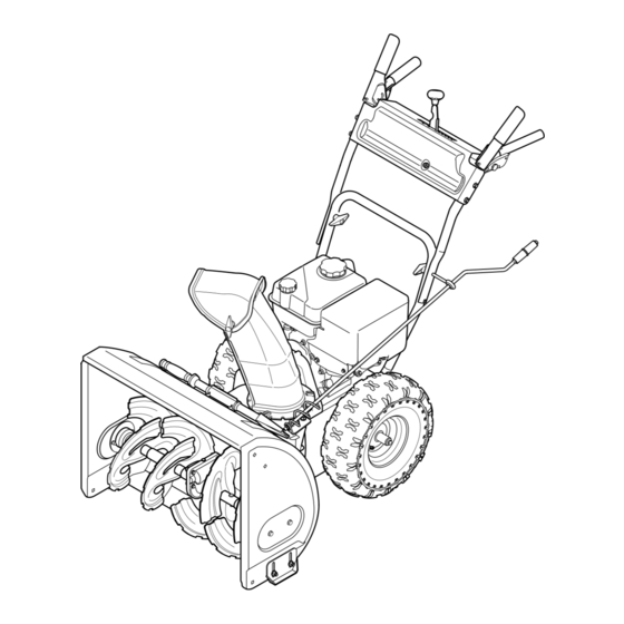
Page 12: Controls & Features
Controls and Features Shift Lever Drive Control Auger Control Chute Directional Control Chute Assembly Clean Out Muffler Tool Oil Fill Gas Cap Primer Throttle Control Choke Electric Start Control Button Oil Drain Recoil Starter Electric Starter Augers Handle Outlet Skid Shoe Figure 4-1 Choke Control Snow thrower controls and features are described below and... - Page 13 Throttle Control Auger Control The throttle control is located on the rear of the engine. It regulates the speed of the engine and will shut off the engine when moved into the STOP position. Primer Pressing the primer forces fuel directly into the engine’s carburetor to aid in cold- weather starting.
- Page 14 Chute Directional Control Chute Clean-Out Tool WARNING! Never use your hands to clear a clogged chute assembly. Shut off engine and remain behind handles until all moving parts have stopped before unclogging the chute assembly. The chute clean-out tool is conveniently fastened to the rear of the auger housing with a mounting clip.
-
Page 15: Operation
Operation Starting the Engine Plug the extension cord into the electric outlet located on the engine. Plug the other end of extension cord into WARNING! Always keep hands and feet clear of a three-prong 120-volt, grounded, AC outlet in a well- moving parts. -
Page 16: Stopping The Engine
To Engage Drive Recoil Starter CAUTION! Do not pull the starter handle while the With the throttle control in the Fast (rabbit) position, move engine is running. shift lever into one of the six forward (F) positions or two reverse (R) positions. Select a speed appropriate for the snow conditions and a pace you’re comfortable with. -
Page 17: Maintenance & Adjustment
Maintenance & Adjustments Maintenance Lubrication Engine Gear Shaft Refer to the Engine Maintenance section. The gear (hex) shaft should be lubricated at least once a season or after every twenty-five (25) hours of operation. Shave Plate and Skid Shoes Carefully pivot the snow thrower up and forward so that it The shave plate and skid shoes on the bottom of the snow rests on the auger housing. - Page 18 Adjustments Auger Shaft At least once a season, remove the shear pins from the auger Shift Cable shaft. Spray lubricant inside the shaft and around the spacers and the flange bearings found at either end of the shaft. Reinstall the If the full range of speeds (forward and reverse) cannot be shear pins.
- Page 19 Drive Control Chute Bracket Adjustment When the drive control is released and in the disengaged “up” If the spiral at the bottom of the chute directional control is not position, the cable should have very little slack. It should NOT be fully engaging with the chute assembly, the chute bracket can be tight.
-
Page 20: Engine Maintenance
Engine Maintenance WARNING! Periodic inspection and adjustment of the engine is essential if To prevent accidental start-up, shut off high level performance is to be maintained. Regular maintenance the engine and remove the key before performing will also ensure a long service life. The required service intervals any type of engine maintenance. -
Page 21: Spark Plug
Spark Plug Check that the spark plug washer is in good condition and thread the spark plug in by hand to prevent cross- WARNING! DO NOT check for spark with spark threading. plug removed. DO NOT crank engine with spark After the spark plug is seated, tighten with a spark plug plug removed. -
Page 22: Service
Service Belt Replacement Carefully pivot the snow thrower up and forward so that it rests on the auger housing. Auger Belt Remove the frame cover from the underside of the snow thrower by removing the self-tapping screws which secure To remove and replace your snow thrower’s auger belt, proceed it. - Page 23 Remove the belt from around the auger pulley, and slip the Drive Belt belt between the support bracket and the auger pulley. To remove and replace your snow thrower’s drive belt, proceed See Fig. 8-5. as follows: To prevent spillage, remove all fuel from tank by running engine until it stops.
-
Page 24: Friction Wheel Removal
Friction Wheel Removal Back out the stop bolt to increase the clearance between the friction wheel disc and friction wheel. See Fig. 8-7. If the snow thrower fails to drive with the drive control engaged, and performing the drive control cable adjustment fails to correct the problem, the friction wheel may need to be replaced. - Page 25 Carefully remove the hex nut which secures the hex shaft Follow the previous steps in reverse order to reassemble to the snow thrower frame and lightly tap the shaft’s end to components. If you’re disassembling the friction wheel and dislodge the ball bearing from the right side of the frame. replacing only the rubber ring, proceed as follows: See Fig.
-
Page 26: Troubleshooting
Troubleshooting Problem Cause Remedy Engine fails to start Choke not in CHOKE position. Move choke to CHOKE position. Spark plug wire disconnected. Connect wire to spark plug. Fuel tank empty or stale fuel. Fill tank with clean, fresh gasoline. Engine not primed. Prime engine as instructed in the Operation Section. -
Page 27: Replacement Parts
Replacement Parts Component Part Number and Description 929-0071 Extension Cord, 110V 954-04050 Auger Drive Belt 754-0367 Wheel Drive Belt 684-04153 Friction Wheel Assembly 935-04054 Friction Wheel Rubber 925-1658 Halogen Lamp, 12V, 27W 738-04124A Shear Pin, 1.50 714-04040 Bow-tie Cotter Pin 784-5580 Slide Shoe, Standard (Steel) 731-06439... -
Page 28: Attachments And Accessories
Attachments & Accessories The following attachments and accessories are available for your snow thrower. Phone (800) 800-7310 for information regarding compatibility, price and availability (have your full model number and serial number ready). Model Number Description OEM-390-679 Drift Cutter Kit OEM-390-674 Heavy Duty Snow Cab 490-241-0009... - Page 29 Notes...
- Page 30 Elsewhere in the United States, new non-road, spark-ignition engines certified for model 2005 and later, must meet similar standards set forth by the U. S. EPA. MTD must warranty the emission control system on your engine for the period of time listed below, provided there has been no abuse, neglect or improper maintenance of your small off-road engine.
- Page 31 (c) MTD will include a copy of the following emission warranty parts list with each new engine, using those portions of the list applicable to the engine.
- Page 32 MANUFACTURER’S LIMITED WARRANTY FOR The limited warranty set forth below is given by MTD LLC with c. Service completed by someone other than an authorized service respect to new merchandise purchased and used in the United States dealer. and/or its territories and possessions, and by MTD Products Limited d.
Need help?
Do you have a question about the 600 series and is the answer not in the manual?
Questions and answers