Table of Contents
Advertisement
Quick Links
Advertisement
Table of Contents

Subscribe to Our Youtube Channel
Related Manuals for Extech Instruments BT100


Summary of Contents for Extech Instruments BT100
- Page 1 User's Guide Battery Capacity Tester Model BT100...
-
Page 2: Warranty
RS232 PC port and Windows compatible software. Warranty EXTECH INSTRUMENTS CORPORATION warrants the basic instrument to be free of defects in parts and workmanship for one year from date of shipment (a six month limited warranty applies on sensors and cables). If it... -
Page 3: Specifications
Specifications Measuring method: Resistance (AC four-terminal method). A/D conversion: Dual slope method. Display: Dual display LCD and LEDs (comparator output). Sampling rate: 1 set (resistance & voltage measurements)/second. Open-Circuit terminal voltage: 3.5Vpp max. Input over range: “OL” display. Low battery detection: display. - Page 4 Electrical Specifications Conditions to guarantee accuracy: Temperature: 23°C ± 5° Humidity: 80%RH or less (non-condensing). Zero adjustment: After zero adjustment for each range. Resistance measurement Temperature coefficient: (±0.1% rdg ± 0.5digits)/°C Measuring current frequency: 1KHz ± 10% Measuring burden voltage: 1.5mVAC Range Resolution...
-
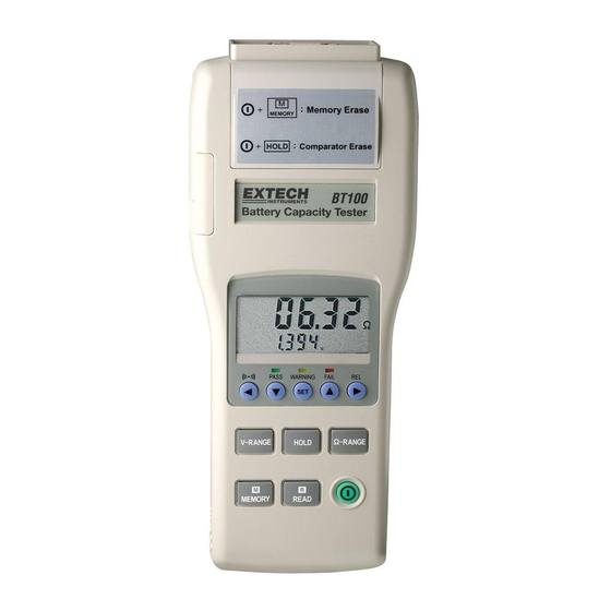
Page 5: Meter Description
Meter Description Power button: Power on /off R READ button: Press R button to show the manual logged readings. Press R READ button again to stop reading. M MEMORY button: Under the manual logging mode, the tester stores each single set of logged reading to the memory by pressing M MEMORY button. - Page 6 Display Description 1. Measured resistance reading (High or Low limit of resistance on the comparator settings) 2. Measured voltage reading (High or Low limit of voltage on the comparator settings). 3. The assigned number of comparator: 99 sets 4. The location for the manual logged data. 5.
-
Page 7: Basic Operation
Basic Operation Preparation The following safety information must be observed to ensure maximum personal safety during the operation of this tester. To avoid electric shock when replacing the batteries first disconnect the leads from the object to be measured. Check the battery polarity carefully when inserting the batteries. Be sure to dispose of used batteries properly. - Page 8 Operation Connect the red test lead to the “+” jack and the black test lead to the “-” jack. 1. Press Power button to turn on the tester. 2. Connect the red test probe to the positive battery terminal, and the black test probe to the negative battery terminal.
- Page 9 Comparator (99 sets) The comparator function compares the measured values with preset High and Low limit values for internal resistance and voltage level, and determines the range that the measurement should fall into. Then, according to the following conditions, lights the corresponding LED, and sounds a beeper under the WARNING and FAIL cases.
-
Page 10: Data Logging
Datalogging Manual Data Logging (999 sets) 1. Log the reading one by one to the memory by pressing the MEMORY button. “DATA M NO XXX” will appear on the LCD for one sec. to indicate the memorized location. 2. Press READ button to review the logged readings. - Page 11 Windows 95, 98, 2000, NT, ME, or XP Operating System Installing the Windows Application Program 1. Connect the BT100 to the serial PC port (COM1 or COM2) using the 9-pin female connector to the 9-pin male serial PC port cable supplied.
- Page 12 Data Acquisition Mode In the data acquisition mode, the meter is connected to the computer while taking readings. At the same time the readings are taken, they are displayed and stored on the computer. The readings can be displayed as a List, a Voltage graph or a Resistance graph. Sampling Rate Setting for Data Acquisition Mode The sampling rate for the data acquisition mode can be set from 1 reading per...
- Page 13 Datalogger Mode The meter’s internal datalogger memory stores readings in files. Each file is created when a datalogging session is started and then stopped using the MEMORY button (described earlier). The Datalogger screen lists each file (1, 2, 3,…) with the ohm range, voltage range, sampling time and the number of records stored in the file.
-
Page 14: Maintenance
For the latest version of this User’s Guide, Software updates, and other up-to-the-minute product information, visit our website: www.extech.com Copyright © 2005 Extech Instruments Corporation (a FLIR company). All rights reserved including the right of reproduction in whole or in part in any form.
Need help?
Do you have a question about the BT100 and is the answer not in the manual?
Questions and answers