Table of Contents
Advertisement
Quick Links
INSTALLATION AND SERVICE MANUAL
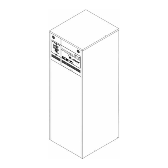
FIG. 1 Front View 1,500,000 - 2,000,000 Btu/hr Models
WARRANTY
Installation and service must be performed by a qualified
service installer, service agency or the gas supplier.
Factory warranty (shipped with unit) does not apply to
units improperly installed or improperly operated.
Experience has shown that improper installation or system
design, rather than faulty equipment, is the cause of most
operating problems.
1. Excessive water hardness causing a lime/scale build-up
in the copper tube is not the fault of the equipment and
is not covered under the manufacturer's warranty (See
Water Treatment and Water Chemistry).
2. Excessive pitting and erosion on the inside of the
copper tube may be caused by too much water velocity
through the tubes and is not covered by the
manufacturer's warranty (See Boiler Flow Rates and
Temperature Rise for flow requirements).
Power-Fin
HOT WATER HEATING BOILERS
DOMESTIC HOT WATER SUPPLY BOILERS
1,500,000, 1,700,000 and 2,000,000 Btu/hr MODELS
®
4:1
FIG. 2 Rear View 1,500,000 - 2,000,000 Btu/hr Models
SPECIAL INSTRUCTIONS
TO OWNER
NOTE:
Retain this manual for future reference.
This manual supplies information for the installation,
operation and servicing of the appliance. It is strongly
recommended that this manual be reviewed completely
before proceeding with an installation.
WARNING:
IMPROPER INSTALLATION, ADJUSTMENT,
ALTERATION, SERVICE OR MAINTENANCE
can cause injury or property damage. Refer to this
manual. For assistance or additional information,
consult a qualified installer, service agency or the gas
supplier.
PBE/PFE-i&s-03
Advertisement
Table of Contents

Related Manuals for Lochinvar 1,500,000 Btu/hr


Summary of Contents for Lochinvar 1,500,000 Btu/hr
-
Page 1: Warranty
PBE/PFE-i&s-03 INSTALLATION AND SERVICE MANUAL Power-Fin ® HOT WATER HEATING BOILERS DOMESTIC HOT WATER SUPPLY BOILERS 1,500,000, 1,700,000 and 2,000,000 Btu/hr MODELS FIG. 1 Front View 1,500,000 - 2,000,000 Btu/hr Models FIG. 2 Rear View 1,500,000 - 2,000,000 Btu/hr Models SPECIAL INSTRUCTIONS WARRANTY TO OWNER... -
Page 2: Safety Warnings
CHECKING EQUIPMENT Upon receiving equipment, check for signs of shipping damage. Pay particular attention to parts accompanying the boiler, which may show signs of being hit or otherwise being mishandled. Verify total number of pieces shown on packing slip with those actually received. In case there is damage or a shortage, immediately notify carrier. -
Page 3: Table Of Contents
CONTENTS Warranty ........1 Changeable Data Points ..35 Safety Warnings . -
Page 4: Codes
of such requirements, the installation shall conform to the OWNER WARNING: latest edition of the National Fuel Gas Code, ANSI Z223.1. Where required by the authority having jurisdiction, the The information contained in this manual is intended installation must conform to American Society of for use by qualified professional installers, service Mechanical Engineers Safety Code for Controls and Safety technicians or gas suppliers. -
Page 5: Clearances
CLEARANCES FROM COMBUSTIBLE CONSTRUCTION 24" TOP MIN. 0" RIGHT SIDE 24" REAR MIN. 0" LEFT SIDE 24" FRONT MIN. FROM PIPING FIG. 3 Clearances from Combustible Construction - FIG. 4 Clearances from Combustible Construction - Front Rear appliance. The clearance labels on each appliance note the TABLE —... - Page 6 The equipment room MUST be provided with properly sized openings to assure adequate combustion air and proper ventilation when the unit is installed with a basic Category IV venting system. FIG. 7 Combustion Air from Interior Space 3. If air is taken from another interior space, each of the two openings specified above should have a net free area of one square inch for each 1000 Btu (22 cm per kW) of...
- Page 7 TABLE — B Minimum Recommended Combustion Air Supply to Equipment Room COMBUSTION AIR SOURCE Boiler Outside Air* Outside Air* Inside Air Input 2 - Openings 1 - Opening 2 - Openings 1,500,000 375 in (2,419 cm 500 in (3,226 cm 1500 in (9,677 cm 1,700,000...
-
Page 8: Construction Air Filter
CONSTRUCTION AIR FILTER FIG. 9 Construction Air Filter A construction air filter is provided with the appliance as TABLE — C shipped. An air filter is provided for installation on the Construction Air Filter Kits combustion air inlet located at the rear of the appliance. This filter is For Temporary Use Only on an appliance that Construction must be operated for temporary heat or hot water when a... -
Page 9: Category Iv Venting
sidewall. All appliances are shipped from the factory Category IV Venting equipped for Category IV venting. The optional Direct Vent and DirectAire venting systems will require the A CATEGORY IV POSITIVE installation of specific vent kits and venting materials. The PRESSURE VENTING SYSTEM following is a detailed explanation of the installation requirements for each venting system, components used... -
Page 10: Flue Pipe Materials
result in a hazardous condition where flue gases spill into There shall be no reductions in vent diameter. an occupied living space. Consult the induced draft fan manufacturer to size the induced draft fan and to determine Horizontal portions of the venting system shall be the diameter of the common vent pipe required for a supported to prevent sagging. -
Page 11: Masonry Chimneys
The venting system shall terminate at least 4 feet (1.2 m) the vent manufacturer's instructions, shall be provided as a below, 4 feet (1.2 m) horizontally from, or 1 foot (30 cm) drain line from the tee. The drain tubing must have a trap above any door, window or gravity air inlet into any provided by a 4 inches (10.2 cm) diameter circular trap building. -
Page 12: Vertical Terminations
VERTICAL VENTING 10' OR LESS TERMINATIONS Follow all General Category IV Vent Termination Clearances. 2' MIN 2' MIN 3' MIN 10' OR LESS 2' MIN 3' MIN RIDGE WALL OR CHIMNEY CHIMNEY PARAPET FIG. 15 Vent Termination from Flat Roof 10' or Less from Parapet Wall CHIMNEY 10' OR MORE... - Page 13 The opening through the wall for installation of the sidewall vent cap must provide an air space clearance of 2 inches (5.1 cm) around the flue pipe. The diameter of the opening for installation of the sidewall cap will be 4 inches (10.2 cm) larger (minimum) than the nominal diameter of the installed vent pipe to the sidewall cap.
-
Page 14: Direct Vent Systems
The sidewall vent termination must be at least 8 feet The Direct Vent and Intelli-Vent Systems require the (2.4 m) horizontally from any combustion air intake installation of an additional pipe to supply combustion air located above the sidewall termination cap. from outdoors directly to the appliance. -
Page 15: Vertical Direct Vent
Select air inlet pipe material from the following specified material used. The PVC, CPVC, ABS, Dryer Vent or Flex materials: Duct air inlet pipe should use a silicone sealant to ensure a proper seal at the appliance connection and the air inlet cap PVC, CPVC or ABS (6", 7"or 8"... -
Page 16: Air Inlet Pipe Length Requirements
The air inlet cap for the vertical roof top air inlet is assembled from components purchased locally. The air inlet cap consist of two 90° elbows installed at the point of termination for the air inlet pipe. The first 90° elbow is installed on the rooftop at the highest vertical point of the 12"... -
Page 17: Multiple Vertical Direct Vent Installations
Multiple Vertical Direct Vent Installations The maximum installed length of the air inlet pipe from the appliance to the air inlet cap is 50 equivalent feet (15.2 m) in length. The maximum installed length of the flue pipe from the appliance to the termination cap is 50 equivalent feet (15.2 m) in length. -
Page 18: Location Requirements
The part numbers for the required sidewall air inlet cap kit horizontally and 12 inches (0.30 m) below the point of flue are listed by unit size. The manufacturer, in accordance gas termination (vent cap) if it is located within a 10 foot with CSA/CGA requirements, must furnish the sidewall air (3.05 m) radius of the flue outlet. -
Page 19: Directaire Vent Systems
DIRECTAIRE VENT SYSTEMS VERTICAL DIRECTAIRE WITH SIDEWALL COMBUSTION AIR A DirectAire vent system is a Category IV flue installed with a separate combustion air pipe to the outdoors. The DirectAire vent system terminates the flue and the combustion air inlet pipe in different pressure zones. The DirectAire vent system may terminate the flue and combustion air in any one of three configurations. -
Page 20: Sidewall Flue - Rooftop Air
Combustion air supplied from outdoors must be free of SIDEWALL COMBUSTION contaminants (See Combustion and Ventilation Air). To AIR INLET prevent recirculation of flue products in to the combustion air inlet, follow all instructions in this section. Incorrect installation and/or location of the air inlet cap can allow the discharge of flue products to be drawn into the combustion process on the heater. -
Page 21: Sidewall Flue - Sidewall Air
be located a minimum of 12 inches (0.30 m) above the roof CAUTION: or above normal levels of snow accumulation. Appliances that are shut down or will not operate Location of a Rooftop Air Inlet Cap may experience freezing due to convective airflow in the air inlet pipe connected to the appliance. - Page 22 Follow all requirements in the General Category IV accordance with CSA/CGA requirements, must furnish Venting sections for proper installation and of venting flue both the sidewall air inlet and flue cap. Each kit includes products horizontally to the outdoors. All other general the both the special combustion air inlet cap and the installation requirements must be followed.
-
Page 23: Gas Supply
incomplete combustion and potentially hazardous levels of TABLE — L carbon monoxide in the flue products. This will cause Manifold Gas Pressure operational problems with the heater and possible spillage Manifold Pressure of flue products that can cause personal injury, death or Settings at Full Fire property damage. -
Page 24: Gas Pipe Sizing
TABLE — N Recommended Gas Pipe Size Single Appliance Installations Distance from Meter INPUT 0 - 50 ft. 51 ft. - 100 ft. 101 ft. - 200 ft. 201 ft. - 300 ft. 301 ft. - 500 ft. 1,500,000 2” 2 1/2”... -
Page 25: Supply Pressure Measurement
4. Run pipe or tubing to the units gas inlet. If tubing is CHECKING GAS used, obtain a tube to pipe coupling to connect the SUPPLY PRESSURE tubing to the units gas inlet. 5. Install a sediment trap in the supply line to the units gas inlet. - Page 26 10. If gas supply pressure is within normal range, proceed IMPORTANT: to remove gas manometer and replace pressure tap fittings in the gas piping to the appliance. Upon completion of any testing on the gas system, leak test all gas connections with a soap solution 11.
-
Page 27: Water Connections
3. Set the Diagnostic Information Center to a setpoint WATER CONNECTIONS which will fire the burner at 100% of rated input. 4. As the appliance comes on and fires, record the inches of water column of displacement on both sides of the manometer. -
Page 28: Heat Exchanger
formation on the heat exchanger. An appliance allowed to HEAT EXCHANGER sustain operation at water temperatures lower than the specified minimum temperature may not provide enough heat from the burner to maintain water temperatures in the heat exchanger above the 140°F (60°C) dew point of flue products. -
Page 29: Relief Valve
RELIEF VALVE RATIO GAS VALVE This unit is supplied with a relief valve(s) sized in accordance with ASME Boiler and Pressure Vessel Code, Section IV ("Heating Boilers"). The relief valve(s) is installed in the vertical position and mounted in the hot water outlet. -
Page 30: Diaphragm Gas Valve
provided on the valve assembly to indicate the position of connections from components requiring an external vent the valve seat. Operation of the gas valve in combination line are provided on the component. These vent line with the combustion air blower allows the burner input rate connection points may be accessed by removing the top to vary from 25% to 100% based on temperature demand. -
Page 31: Jacket
1. All wiring between the appliance and field installed JACKET ASSEMBLY devices shall be made with type T wire [63 F (35 rise]. Inner Jacket - The inner jacket assembly is constructed from a special corrosion resistant stainless steel. Screws 2. -
Page 32: Component Location Drawings
SLIDE DISPLAY AND FORWARD INDICATING LEDs FIG. 44 Internal Control Panel Component Access Drawing TRANSFORMER ELECTRONIC TEMPERATURE LOW WATER CUTOFF CONTROL CIRCUIT BOARD (OPTIONAL) RESET IGNITION MODULE FIG. 45 Transformer, Circuit Boards and Relay Locations LOW WATER CUTOFF OPTIONAL LIGHT TEST SWITCH AND SWITCHES LOW WATER CUTOFF... -
Page 33: Variable Frequency Drive
A component, transformer and relay mounting control When removing the variable frequency drive from the panel is located along the right front control panel, along appliance, disconnect the power wires to the combustion the right side of the exterior jacket panel. This panel air blower at the terminals on the variable frequency drive. -
Page 34: Gas Pressure Switches
Electronic Temperature Control - The temperature controller for this appliance is based on an electronic controller platform with software customized for operation of the Lochinvar Power-Fin. All of the appliances internal safety, operating and ignition controls interface with the electronic controller. Local communication, programming, display of operational sequence LED's, display of fault FIG. -
Page 35: Diagnostic Information Center
The Electronic Temperature Control may have default DOWN: When pressed, this key decreases the value of any values for the control points specified at the time the currently displayed setpoints or allows scrolling through appliance is tested at the factory. Job site specific values non-numeric changeable parameters such as those of the may be programmed into the control at the time the pump and controlling sensor selections. -
Page 36: Operation Status Led's
Setpoint Differential: On water heaters and boilers, this is Burner On: This LED indicates that the gas valve is the number of degrees that the water temperature must fall turned on and modulation may now occur. When below the setpoint temperature before a call for heat illuminated, the ignition module is providing power to the initiates. -
Page 37: Temperature Adjustment
FIG. 53 Diagnostic Information Center Display Panel FIG. 52 Diagnostic Information Center Display Panel (with Outdoor Air Reset Function) TEMPERATURE ADJUSTMENT OUTDOOR RESET PROCEDURE FUNCTION SELECTIONS (1) Press the SELECT key until the desired adjustable (OPTIONAL ON HEATING BOILERS ONLY) item's LED is illuminated and its' current setting is displayed. -
Page 38: Lockout Procedure
appliance leaves the factory. It is also intended to keep NOTE: certain critical operating parameters from being inadvertently changed while making basic adjustments. Outdoor Air Reset function not available on a water heater application. LIMITED ACCESS FEATURES Limited access features are features or settings that may These functions are shown in the screens of the Diagnostic significantly affect the operation of the controller and Information Center. -
Page 39: Error Displays
without having to unnecessarily re-enter the limited access key while “OLoc” is in the display will show the current mode before completing controller and display settings. outdoor air lockout setting. When the outdoor air The following are the feature settings that can be changed temperature is greater than the outdoor air lockout setting with the limited access feature: and the outdoor air reset is enabled, the appliance will turn... -
Page 40: Condensate Trap Installation
A Manual Reset High Limit control is located on the inside Place the appliance in operation. While the appliance of the left front control panel, behind the display. The is firing, check the 1/2" connection on the condensate setting of this control knob limits maximum discharge trap for flue gas spillage. -
Page 41: Hot Surface Ignition Control
Service Parts This appliance uses a proven electronic ignition control module and a hot surface igniter. The electronic ignition module is not repairable. Any modification or repairs will invalidate the warranty and may create hazardous conditions that result in property damage, personal injury, fire, explosion and/or toxic gases. -
Page 42: Diagnostic Status
ignition module will pause for a fixed time period. The timed length of the pause is based on the type of fault sensed by the control module. At the end of this timed D. C. MICROAMP METER pause, the ignition module will attempt a new trial for ignition sequence. -
Page 43: Combustion Air Blower
This appliance uses a single cylindrical burner installed This appliance uses a sealed air blower to provide vertically into the cavity located in the center of the combustion air for the burner and operate the Category IV primary heat exchanger. There is a unique burner for each venting system. -
Page 44: Lighting Instructions
4. This appliance is equipped with an ignition device, LIGHTING INSTRUCTIONS which automatically lights burner. 5. DO NOT try to light the burner by hand. FOR YOUR SAFETY, READ BEFORE OPERATING 6. Turn the main manual gas cock handle clockwise to the "OFF"... -
Page 45: Sequence Of Operation
11. If the appliance will not operate, follow the SEQUENCE OF OPERATION instructions "To Turn Off Gas To Appliance" and call your service technician or gas supplier. The power switch is placed in the "ON" position. TO TURN OFF GAS 120 VAC Power supplied to the control junction box TO APPLIANCE and to the external circulating pump (if installed in a... -
Page 46: Maintenance
19. Variable Ratio Gas Valve senses the pressure from the MAINTENANCE Combustion Air Blower and supplies gas to the orifice and into the Blower inlet to pre-mix. Listed below are items that must be checked to ensure safe reliable operations. Verify proper 20. -
Page 47: Flame Patterns
a. Normal Flame: A normal flame at 100% of burner Use extreme care when operating an appliance for input is blue, with slight yellow tips, a well defined temporary heat during new construction. Airborne flame and no flame lifting. contaminants such as dust, dirt, concrete dust or dry wall dust can be drawn into the burner with the b. -
Page 48: Changing The Hsi
8. Remove the sensing tubes from the air ratio gas valve 5. CHANGING THE HOT SURFACE IGNITER to the combustion air blower. 1. Turn off main electrical power to the appliance. 9. Remove the 6 nuts holding the blower assembly to the 2. -
Page 49: Heat Exchanger Inspection
6. HEAT EXCHANGER INSPECTION bristle brush. Use a vacuum to remove loose soot from surfaces and inner chamber. 10. The heat exchanger can be removed by disconnecting all water piping to the heat exchanger, removing the screws holding the heat exchanger to the top of the inner jacket and sliding the heat exchanger towards the front of the appliance. -
Page 50: Control Circuit Voltage
9. CONTROL CIRCUIT VOLTAGE 11. COMBUSTION AIR MEASUREMENT This appliance uses a transformer to supply a low voltage control circuit. The voltage on the secondary This appliance uses a variable speed combustion air side should be 24 to 28 VAC when measured with a blower to operate the combustion process and venting voltmeter. -
Page 51: Freeze Protection
Set the Command Display to a setpoint which rooms or where temperatures may drop to the freezing will fire the burner at 100% of rated input. point or lower. If freeze protection is not provided for the system, a low ambient temperature alarm is recommended As the appliance comes on and fires, record the for the mechanical room. -
Page 52: Heating Boiler
FREEZE PROTECTION FOR A HEATING BOILER HEATING BOILER SYSTEM INSTALLATIONS (IF REQUIRED) 1. Use only properly diluted inhibited glycol antifreeze PIPING OF THE BOILER SYSTEM designed for hydronic systems. Inhibited propylene glycol is recommended for systems where incidental The drawings in this section show typical boiler piping contact with drinking water or any potable water is installations. -
Page 53: Boiler Pump Operation
the burner fires. The pump will continue operate while the BOILER CIRCULATOR burner is firing. The pump will run for a minimum 30 REQUIREMENTS second period after the temperature setpoint is satisfied. This timing is selectable from the Diagnostic Information This is a low mass, high efficiency hot water boiler which Center. -
Page 54: Minimum Water Temperatures
The boiler primary piping system must have a circulator LOW TEMPERATURE installed in the main system loop to carry the heated boiler BYPASS REQUIREMENTS water to the point of use in the main system. Multiple boilers may also be installed with a To prevent condensation problems, a boiler MUST NOT be primary/secondary manifold system. -
Page 55: Three Way Valves
the boiler. Constant water flow through the boiler must be TABLE — T provided at all times when the boiler is operating. Maximum Flow for Heating Boiler The boiler's operating temperature sensor can be remote CAUTION: mounted in a bulbwell installed in the system water flow to The maximum flow rate through the control boiler operation at a low temperature range. -
Page 56: High Flow Bypass
BOILER BYPASS REQUIREMENTS TABLE — U Boiler Temperature Rise at Maximum Flow Temperature Rise at Full Rate Fire and 90 GPM Maximum Flow Btu/hr Input Temperature Rise 1,500,000 29°F (16.1°C) 1,700,000 33°F (18.3°C) 2,000,000 39°F (21.7°C) FIG. 72 Boiler Bypass Piping for High Flow Systems The installer must ensure that the boiler is supplied with adequate flow without excessive temperature rise. -
Page 57: Placing The Boiler In Operation
SYSTEM TEMPERATURE RISE CHART TABLE — V Temperature Rise and Head Loss Based on Boiler Output in BTU/hr 30° Δ Δ T 35° Δ Δ T 40° Δ Δ T 45° Δ Δ T 50° Δ Δ T 55° Δ Δ T 60°... -
Page 58: Boiler Temperature Control
14. Review wiring to an energy management system and 30. Ensure that inlet water temperature does not fall below wiring to any remote temperature sensors. the specified minimum for the boiler. Boiler Set-Up 31. Based on system demand, the boiler may run for an extended period of time at a reduced rate of input to maximize efficiency. - Page 59 in a bulbwell installed in the inlet side of the heat a remote on/off thermostat to these wires will allow the exchanger top header. The outlet sensor is located in a unit to be switched on and off by making or breaking a bulbwell on the outlet side of the heat exchanger top 24 VAC control circuit.
-
Page 60: Typical Piping
DOMESTIC This section applies only to those appliances used to supply domestic hot water, installed with a storage tank(s). HOT WATER circulating pump MUST be installed in piping assembly to the storage tank and valves used to control water velocity through SUPPLY BOILER the appliance. -
Page 61: Temperature Rise
If higher flow rates are required through the water heater, 4. Check diameter and length of the piping between the an optional Cupro-Nickel heat exchanger is available. storage tank and water heater against the head capacity Consult the factory for specific application requirements. of the circulating pump. -
Page 62: Piping Requirements
be heated. Water with a hardness of less than 5 grains per MULTIPLE WATER gallon will usually have a low pH which can be aggressive HEATER INSTALLATIONS and corrosive causing non-warrantable damage to the heater, pump and associated piping. Corrosion due to water chemistry generally shows up first in the hot water system because heated water increases the rate of corrosive chemical reactions. -
Page 63: Pump Operation
proper operation. As shipped from the factory, the TABLE — Y operating sensor is installed in a bulbwell mounted in the Common Water Manifold Size for inlet piping to the water heater. When the pump cycles off Multiple Water Heater or Hot in normal operation, this sensor location may not adequately sense a quick drop in temperature from a draw Water Supply Boiler Installations... -
Page 64: Temperature Adjustment
If at anytime, during the adjustment process there is no key HEAT EXCHANGER activity for more than 5 seconds the display will revert back to the power up default mode and all information not This is a highly sophisticated heat exchanger designed to previously entered by the enter key will be lost. -
Page 65: Risk Of Scald Warnings
CAUTION: CAUTION: An appliance allowed to operate at return Hotter water increases the risk of scald injury. temperatures below the specified minimum setting may experience problems with the Location of Cold Water Supply Piping Connections operating controls, safety switches, obstruction Incorrect piping of the cold water supply to the system may of the flue gas passages on the heat exchanger, result in excessive low temperature operation causing... -
Page 66: Temperature Limit Control
OPTIONAL RELIEF VALVE HIGH WATER TEMPERATURE LIMIT CONTROL This water heater or hot water supply boiler is normally supplied with a temperature and pressure relief valve sized in accordance with applicable codes. Units may be supplied with an optional pressure only relief valve. When a water heater or hot water supply boiler equipped with this optional relief valve and is piped to a separate storage vessel, the storage vessel must have a properly installed... - Page 67 ELECTRICAL COMBUSTION JUNCTION BOX AIR INLET WATER INLET SUPPLY WATER OUTLET FLUE DRAINS OUTLET Fig. 82 Component Location Drawing - Rear Fig. 81 Component Location Drawing - Front RATIO GAS VALVE DIAPHRAGM VALVE TRANSITION CHAMBER COMBUSTION AIR BLOWER CONTROL PANEL BLOWER MOTOR Fig.
- Page 68 Wiring Diagram 1,500,000, 1,700,000 and 2,000,000 Btu/hr Models LOW VOLTAGE TRANSFORMER 75 or 100VA...
- Page 69 Wiring Diagram (continued) 1,500,000, 1,700,000 and 2,000,000 Btu/hr Models...
- Page 70 Ladder Diagram 1,500,000, 1,700,000 and 2,000,000 Btu/hr Models...
- Page 71 Ladder Diagram (continued) 1,500,000, 1,700,000 and 2,000,000 Btu/hr Models...
- Page 72 CP-5M-10/05-Printed in U.S.A.
Need help?
Do you have a question about the 1,500,000 Btu/hr and is the answer not in the manual?
Questions and answers