Table of Contents

Subscribe to Our Youtube Channel
Related Manuals for Lochinvar EcoKnight EKB45CE


Summary of Contents for Lochinvar EcoKnight EKB45CE
- Page 1 The EcoKnight™ range High Efficiency Gas Fired Condensing Boilers Installation, Commissioning and Maintenance Instructions Models: EKB45CE EKB60CE EKB85CE EKB115CE EKB145CE EKB175CE EKB205CE EKB235CE INS0009 Issue No 8 | October 2013...
-
Page 2: Table Of Contents
INSTALLATION PRECAUTIONS ................................. 15 MAXIMUM LENGTH ..................................... 15 FLUE DISCHARGE ....................................... 15 CONDENSATE DRAIN ....................................15 BOILER CONNECTION ASSEMBLY ................................16 8.7.1 EKB45CE – EKB60CE ................................... 16 8.7.2 EKB85CE – EKB145CE ..................................18 8.7.3 EKB175CE ......................................19 8.7.4 EKB205CE – EKB235CE ..................................20 FLUE TERMINAL INSTALLATION ................................ - Page 3 LPG FUEL ..........................................38 14.1 RELATED DOCUMENTS ..................................... 38 14.2 CONVERSION TO LPG ....................................38 14.2.1 EKB45CE – EKB85CE ..................................39 14.2.2 EKB115CE ....................................... 40 14.2.3 EKB145CE (BEFORE SERIAL NUMBER L09H10120786) ......................41 14.2.4 EKB145CE (FROM SERIAL NUMBER L09H10120786) ........................ 42 14.2.5...
-
Page 4: Introduction
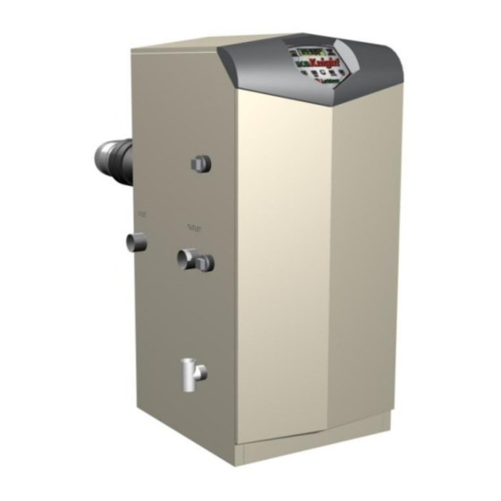
INTRODUCTION The Lochinvar EcoKnight™ range is a floor standing gas fired condensing boiler. The equipment comprises a stainless steel radial burner assembly and a heat exchanger that permits fully condensing operation. The burner is initiated by a full electronic ignition sequence control that incorporates a spark ignition and a flame rectification device for supervision of the flame. -
Page 5: Principal Parts
PRINCIPAL PARTS ITEM DESCRIPTION FUNCTION Allows water to flow through specially designed coils for maximum heat transfer, while providing Stainless steel heat exchanger protection against flue gas corrosion. The coils are encased in a jacket that contains the combustion process. Heat exchanger access cover Allows access to the combustion side of the heat exchanger coils. - Page 6 FRONT VIEW REAR VIEW MODELS EKB45CE – EKB60CE MODELS EKB45CE – EKB60CE LEFT SIDE (INSIDE UNIT) RIGHT SIDE (INSIDE UNIT) MODELS EKB45CE – EKB60CE MODELS EKB45CE – EKB60CE...
- Page 7 REAR VIEW LEFT SIDE (INSIDE UNIT) MODEL EKB85CE – EKB115CE MODEL EKB85CE – EKB115CE REAR VIEW LEFT SIDE (INSIDE UNIT) MODEL EKB145CE MODEL EKB145CE...
- Page 8 REAR VIEW LEFT SIDE (INSIDE UNIT) MODEL EKB175CE – EKB235CE MODEL EKB175CE – EKB235CE...
-
Page 9: Technical Data
TECHNICAL DATA Model Number EKB45CE EKB60CE EKB85CE EKB115CE EKB145CE EKB175CE EKB205CE EKB235CE GENERAL DATA Input (gross) – kW 44.0 61.5 83.5 116.9 146.5 175.8 205.2 234.5 Input (net) – kW 39.6 55.4 75.2 105.3 132.0 158.4 184.9 211.3 Output – kW (50º/30º) 41.2... - Page 10 FIGURE 3.1 ENCLOSURE INSTALLATION CLEARANCES (mm) FIGURE 3.2 PLANT-ROOM INSTALLATION CLEARANCES (mm)
-
Page 11: General Requirements
GENERAL REQUIREMENTS The Lochinvar EcoKnight™ condensing boiler has been designed to operate trouble free for many years. These instructions should be followed closely to obtain the maximum usage and efficiency of the equipment. PLEASE read the instructions fully before installing or using the appliance. -
Page 12: Water Quality
Manufacturer's notes must not be taken in any way as overriding statutory obligations. WATER QUALITY The Lochinvar EcoKnight™ contains a stainless steel heat exchanger; therefore care must be exercised to ensure that the system water and any water treatment are compatible. Whenever a new boiler is connected to an existing system, the pipework must be thoroughly cleaned and flushed to remove debris, rust particles, carbonate deposits and any existing water treatment that might be incompatible with the heat exchanger. -
Page 13: Clearances
Lochinvar Limited. This unit is capable of neutralising 4000 litres of condensate to a pH of 7.0 before releasing it to a drain. -
Page 14: Equipment Gas System Leak Check
Care must be taken not to allow leak detection fluid on or near any electrical parts or connections. FLUE SYSTEM FIGURE 8.1: FLUE TERMINAL POSITIONS Location Description EKB45CE – EKB60CE EKB85CE – EKB235CE Directly below an opening, air brick, opening windows etc. 2000 Above an opening, air brick, opening windows etc. 1000 Horizontally to an opening, air brick, opening windows etc. -
Page 15: Flue System General Requirements
When used as a type C appliance, the approved, purpose designed adaptive flue system should be used. For further details, please contact Lochinvar Limited. When used as a Type B appliance, a suitable flue system constructed of Stainless Steel or Polypropylene with a temperature rating in excess of 120C should be used. -
Page 16: Boiler Connection Assembly
8.7 BOILER CONNECTION ASSEMBLY 8.7.1 EKB45CE – EKB60CE FIGURE 8.2 FLUE CONNECTION DETAILS EKB45CE – EKB60CE ITEM DESCRIPTION Flue Gas Test Point Concentric Adaptor 90 Elbow 80mm Dia, x 250mm Length Air Intake Transition Intake Connection Reducer Exhaust Transition TABLE 8.2... - Page 17 FIGURE 8.3 CUTTING ITEM 5 TO LENGTH To install the flue connection to the EKB45CE – EKB60CE boilers the following procedure should be followed: Insert the exhaust transition (Item 7 in Figure 8.2) into the exhaust port on the boiler.
-
Page 18: Ekb85Ce - Ekb145Ce
8.7.2 EKB85CE – EKB145CE FIGURE 8.4 FLUE CONNECTION DETAILS EKB85CE – EKB145CE ITEM DESCRIPTION Flue Gas Test Point Concentric Adaptor 100mm Dia x 500mm Length 90 Elbow Exhaust Transition Intake Connection Air Intake Transition TABLE 8.3 FLUE CONNECTION DETAILS EKB85CE – EKB145CE "X"... -
Page 19: Ekb175Ce
To install the flue connection to the EKB85CE – EKB145CE boilers the following procedure should be followed: Insert the exhaust transition (Item 6 in Figure 8.4) into the exhaust port on the boiler. Insert the flue temperature sensor (supplied with the boiler) into the location hole on the exhaust transition. NOTE: IF THE FLUE TEMPERATURE SENSOR IS NOT FITTED, THE FLUE GAS MAY EXCEED THE MAXIMUM TEMPERATURE RATING OF THE FLUE AND CAN LEAD TO SEVERE PERSONAL INJURY, DEATH... -
Page 20: Ekb205Ce - Ekb235Ce
To install the flue connection to the EKB175CE boiler the following procedure should be followed: Insert the exhaust transition (Item 6 in Figure 8.6) into the exhaust port on the boiler. Insert the flue temperature sensor (supplied with the boiler) into the location hole on the exhaust transition. NOTE: IF THE FLUE TEMPERATURE SENSOR IS NOT FITTED, THE FLUE GAS MAY EXCEED THE MAXIMUM TEMPERATURE RATING OF THE FLUE AND CAN LEAD TO SEVERE PERSONAL INJURY, DEATH... -
Page 21: Flue Terminal Installation
A kit of components to facilitate conventional fluing of the appliance is available from Lochinvar Limited. Insert the exhaust transition into the exhaust port of the boiler. -
Page 22: Type C
8.8.3 TYPE C When the boiler is installed as a Type C appliance, the flue system should be installed as follows: Confirm that the roof flashing is correct for the type of roof through which the terminal is to be installed. (See Figure 8.8) Determine the desired location for the flue terminal, taking into account minimum distances as detailed in Figure 8.1, Table 8.1 and the relevant British Standards. -
Page 23: Type C
If a horizontal flue terminal is to be fitted less than 2 metres from ground level or in a location where it can be touched from a window, door or balcony, a terminal guard must be fitted. For the EKB45CE – EKB145CE, use Lochinvar Part Number FTG0001 and for the EKB175CE –... -
Page 24: Air Supply
(To Internal Space) Model (Room) (kW) (kW) High High EKB45CE 43.9 39.6 EKB60CE 58.6 52.8 1060 TABLE 9.1 COMBUSTION VENTILATION REQUIREMENTS EKB45CE – EKB60CE Plant Room Enclosure Input Input Medium High Medium High Model (Gross) (Net) Summer Use Summer Use Summer Use... -
Page 25: Water Connections
OPEN VENTED SYSTEM ARRANGEMENT The Lochinvar EcoKnight™ can be used in an open vented arrangement provided that a vent pipe in accordance with CP 342 or BS6644 as appropriate is fitted. The minimum static head requirement for an open vented system is 0.5 bar. -
Page 26: Circulating Pumps
10.4 CIRCULATING PUMPS A suitable primary pump, sized in accordance with Table 10.2 should be fitted to the inlet to the boiler. Primary pumps are available from Lochinvar Limited as ancillary items. ΔT (°C): 13.89 16.67 19.44 22.22 25.00 Model... -
Page 27: External Controls
11.1 EXTERNAL CONTROLS The Lochinvar EcoKnight™ is compatible with the following control and safety systems: Building Management System (BMS) 0-10VDC analogue input Room thermostat (on/off type) Storage vessel thermostat (on/off type) Storage vessel sensor (modulating type) ... -
Page 28: Low Voltage Connector Strip
LOW VOLTAGE CONNECTOR STRIP AUX. DEVICE 24VAC PILOT SUPPLY AUX. DEVICE PROVING GAS PRESSURE SWITCH FLOW SWITCH ALARM CONTACTS RUNTIME CONTACTS DHW THERMOSTAT ROOM THERMOSTAT/ ZONE CONTROL SYSTEM SENSOR AUXILIARY SENSOR OUTDOOR SENSOR SHIELD GROUND SEQUENCING SHIELD GROUND 0-10VDC EXTERNAL CONTROL FIGURE 11.2 LOW VOLTAGE CONNECTION STRIP... -
Page 29: Electrical Connections
11.3 ELECTRICAL CONNECTIONS Access to the High Voltage and Low Voltage Connection Strips can be made by removing the appropriate knockouts on the back panel of the boiler. All connections should be secured using an appropriate cord anchorage. One cord anchor is supplied with the boiler for securing the mains supply to the unit. -
Page 30: Wiring Diagram
11.6 WIRING DIAGRAM LOW VOLTAGE DISPLAY 230 VAC HIGH VOLTAGE INTEGRATED CONTROL JUNCTION BOX DEPICTS OPTIONAL ITEMS INTERFACE CONNECTION BOARD X1-3 AUX. PUMP X1-5 DEVICE PILOT CN2-16 SUPPLY X1-4 PRIMARY CN4-8 X6-8 CN2-15 PUMP AUX. DEVICE CN2-14 PROVING CN4-2 X6-10 X1-2 CN2-13 SECONDARY... -
Page 31: Ladder Diagram
11.7 LADDER DIAGRAM JUNCTION BOX 230VAC NEUTRAL GROUND TERMINAL STRIP TERMINAL STRIP 230V SUPPLY "L" 230V SUPPLY "N" INTEGRATED CONTROL ON / OFF SWITCH SECONDARY SECONDARY X1-6 PUMP "L" PUMP "N" X1-2 SECONDARY PUMP RELAY SECONDARY PUMP PRIMARY PRIMARY PUMP "L" PUMP "N"... -
Page 32: Smart System Control
12.0 SMART SYSTEM CONTROL 12.1 GENERAL The Lochinvar EcoKnight™ uses the SMART SYSTEM control interface. The control panel display give information on set-up, system status and diagnostic data in words rather than codes. 12.2 SMART SYSTEM CONTROL PANEL... -
Page 33: Sequence Of Operation
If the control does not detect flame by the end of the trial for ignition, the control performs a 10 second postpurge. On the EKB45CE to EKB115CE models, the control will perform another prepurge and will try to light the burner BLR: POSTPURGE, PREPURGE again. -
Page 34: Status Display Screens
12.4 STATUS DISPLAY SCREENS Status Display Screens By using the Previous/Next (◄, ►) arrow keys on the SMART SYSTEM display panel, you can navigate through the six (6) display screens. Each screen will contain two (2) viewable items. The following is a description of the individual items and what they can display: Screen Display shows:... - Page 35 The control has not received a DHW call for heat and has not powered the DHW PUMP: OFF DHW pump The control has received a DHW call for heat and has powered the DHW pump The DHW call for heat has been satisfied and the DHW pump is running for DELAY a fixed time to remove any residual heat.
-
Page 36: Commissioning And Testing
13.0 COMMISSIONING AND TESTING 13.1 ELECTRICAL INSTALLATION Notes on the requirements for electrical installation are provided in Section 11: ELECTRICAL SUPPLY. A schematic drawing of the control circuit is shown in Figure 11.4. 13.2 GAS INSTALLATION For design see Section 7: GAS SUPPLY. See Section 2.0: PRINCIPAL PARTS for details on the position of the gas connection. -
Page 37: Procedure For Initial Lighting
13.4.4 GAS PRESSURE ADJUSTMENT AND COMBUSTION CHECKS The Lochinvar EcoKnight™ series are supplied with a preset gas/air ratio inlet assembly. This must not be tampered with. Any attempt to adjust the gas valve or venturi will invalidate the warranty. Combustion figures should be as follows: Model No. -
Page 38: Installation Noise
Note: On EcoKnight™ boilers with serial numbers prior to F09H10108102, use ORF2025. For EcoKnight™ boilers with serial numbers after F09H10108102 use ORF20000 ‡ On EcoKnight™ EKB145CE boilers with serial numbers before L09H10120786 an orifice conversion is not available. In this instance a LPG set gas valve, Lochinvar Part No. VAL2714 will be required. -
Page 39: Ekb45Ce - Ekb85Ce
After installation is complete, attach the propane conversion label (in the conversion kit bag) next to the boiler rating plate. Attach the LPG caution label (in the conversion kit bag) to the left side of the unit in the lower left corner. Replace the top and front access covers. FIGURE 14.1 CONVERSION PROCEDURE EKB45CE – EKB85CE... -
Page 40: Ekb115Ce
14.2.2 EKB115CE Remove the top and front access covers from the unit (no tools required for removal). Remove the impulse tube and wiring plug from the gas valve. Remove the three screws securing the venturi to the fan. NOTE: When separating the venturi from the fan, take care not to damage the O-ring inside the fan (Figure 14.2). -
Page 41: Ekb145Ce (Before Serial Number L09H10120786)
14.2.3 EKB145CE (BEFORE SERIAL NUMBER L09H10120786) Remove the top and front access covers from the unit (no tools required for removal). Disconnect the wiring plug from the gas valve. Disconnect the impulse tube from the gas valve and venturi assembly and set aside, taking care not to kink the tube. -
Page 42: Ekb145Ce (From Serial Number L09H10120786)
14.2.4 EKB145CE (FROM SERIAL NUMBER L09H10120786) Remove the top and front access covers from the unit (no tools required for removal). Remove the gas valve and manifold from the unit via the unions on each end (Figure 14.4). Remove the three screws mounting the injector plate on the air shroud (Figure 14.4). Remove the four screws securing the manifold adapter to the injector plate taking care not to damage the O-ring. -
Page 43: Ekb175Ce - Ekb235Ce
14.2.5 EKB175CE – EKB235CE Remove the top and front access covers from the unit (no tools required for removal). Remove the four screws and nuts that hold the adaptor flange to the inlet of the venturi. Separate the flange and venturi ensuring the gasket is not damaged. Locate the propane orifice disk from the conversion kit bag. -
Page 44: Lpg Commissioning And Testing
14.3.1 LPG PRESSURE ADJUSTMENT AND COMBUSTION CHECKS The Lochinvar EcoKnight™ series are supplied with a preset gas/air ratio inlet assembly. This must not be tampered with. Any attempt to adjust the gas valve or venturi will invalidate the warranty. Combustion figures should be as follows: Model No. -
Page 45: Burner Inspection
15.3 BURNER INSPECTION The heat exchanger has a sight glass for inspection of the flame picture. NOTE: If the appliance has been in recent operation, this area may be hot. Appropriate precautions should be taken to prevent personal injury. To check the flame picture at high and low fire, the following procedure should be followed: Place the boiler into service mode. -
Page 46: Draining Boiler System
15.6 DRAINING BOILER SYSTEM The boiler must be drained if it is to be shut down and exposed to freezing temperatures. Maintenance and service procedures may also require draining the boiler. Turn off the boiler electrical disconnect switch. Connect a hose to the system drain valve. Locate hose’s discharge in an area where hot water will not cause any damage or injury. -
Page 47: Smart System Control Settings
16.0 SMART SYSTEM CONTROL SETTINGS 16.1 ENTERING THE INSTALLER CODE To access the user control the following procedure should be followed: If the boiler is operating, press the Enter/Reset button to turn the unit off. Press and hold the Menu/Exit button for 5 seconds. At this point the display will change to show: Enter Menu Code: 0000 Press the UP button 9 times. -
Page 48: Ch Offset
16.2.3 CH OFFSET The CH offset parameter sets how many degrees above the setpoint temperature the boiler will go before shutting down. The offset can be adjusted using the Up and Down buttons on the control panel. Once the desired offset is displayed, the Enter/Reset button should be pressed to store the value. -
Page 49: Menu Set F: Outdoor Reset
16.5 MENU SET F: OUTDOOR RESET 16.5.1 MINIMUM AIR TEMPERATURE When the outdoor air temperature drops to or below this point, the boiler outlet temperature will be at its maximum setting (see Figure 16.1). However, if the user set point is set lower, the water temperature will be limited by the user set point instead. -
Page 50: Shift Heating Curve
16.5.5 SHIFT HEATING CURVE The shift heating curve parameter shifts the actual setpoint above the calculated setpoint by the programmed value (see Figure 4.1). The shift can be adjusted in ½ increments using the Up or Down buttons and the desired value stored by pressing the Enter/Reset button. -
Page 51: Menu Set G: Anti-Cycling
16.6 MENU SET G: ANTI-CYCLING 16.6.1 ANTI-CYCLING TIME Once a CH demand is complete, a set amount of time must pass before the control will respond to a new demand. This time period can only be overridden if the differential temperature becomes too great (see next item). The time range of this parameter can be adjusted between 0 and 40 minutes using the Up and Down buttons. -
Page 52: Cascade Address
2 = Cascade 4 = BMS 6 = Thermostat Cascade: The boiler is part of a group of boilers sequenced together. The designated Master boiler determines the total output needed from the group based on the set point and controlling sensor reading. It assigns portions of this output to itself (Master) and the Member boilers. -
Page 53: Menu Set Icirculation Pumps
16.8 MENU SET I CIRCULATION PUMPS 16.8.1 SECONDARY PUMP DELAY The secondary pump delay parameter sets the length of time the secondary (system) pump will run after a heating demand has been satisfied. The time range for this parameter is 0 minutes to 40 minutes and is adjustable (in 10 second steps) using the Up or Down buttons. - Page 54 NOTES NOTES __________________________________________________________________________________ __________________________________________________________________________________ __________________________________________________________________________________ __________________________________________________________________________________ __________________________________________________________________________________ __________________________________________________________________________________ __________________________________________________________________________________ __________________________________________________________________________________ __________________________________________________________________________________ __________________________________________________________________________________ __________________________________________________________________________________ __________________________________________________________________________________ __________________________________________________________________________________ __________________________________________________________________________________ __________________________________________________________________________________ __________________________________________________________________________________ __________________________________________________________________________________ __________________________________________________________________________________ __________________________________________________________________________________ __________________________________________________________________________________ __________________________________________________________________________________ __________________________________________________________________________________ __________________________________________________________________________________ __________________________________________________________________________________ __________________________________________________________________________________ __________________________________________________________________________________ __________________________________________________________________________________ __________________________________________________________________________________ __________________________________________________________________________________ __________________________________________________________________________________ __________________________________________________________________________________...
- Page 55 NOTES NOTES __________________________________________________________________________________ __________________________________________________________________________________ __________________________________________________________________________________ __________________________________________________________________________________ __________________________________________________________________________________ __________________________________________________________________________________ __________________________________________________________________________________ __________________________________________________________________________________ __________________________________________________________________________________ __________________________________________________________________________________ __________________________________________________________________________________ __________________________________________________________________________________ __________________________________________________________________________________ __________________________________________________________________________________ __________________________________________________________________________________ __________________________________________________________________________________ __________________________________________________________________________________ __________________________________________________________________________________ __________________________________________________________________________________ __________________________________________________________________________________ __________________________________________________________________________________ __________________________________________________________________________________ __________________________________________________________________________________ __________________________________________________________________________________ __________________________________________________________________________________ __________________________________________________________________________________ __________________________________________________________________________________ __________________________________________________________________________________ __________________________________________________________________________________ __________________________________________________________________________________ __________________________________________________________________________________...
Need help?
Do you have a question about the EcoKnight EKB45CE and is the answer not in the manual?
Questions and answers