Table of Contents
Advertisement
Advertisement
Table of Contents

Related Manuals for MSI 915GM Speedster MS-9625


Summary of Contents for MSI 915GM Speedster MS-9625
- Page 1 915GM Speedster MS-9625 (v1.X) Workstation Board English Version G52-S9625X1...
-
Page 2: Copyright Notice
If a problem arises with your system and no solution can be obtained from the user’s manual, please contact your place of purchase or local distributor. Alternatively, please try the following help resources for further guidance. Visit the MSI website for FAQ, technical guide, BIOS updates, driver updates, and other information: http://www.msi.com.tw/program/service/faq/ faq/esc_faq_list.php... -
Page 3: Safety Instructions
Safety Instructions Always read the safety instructions carefully. Keep this User’s Manual for future reference. Keep this equipment away from humidity. Lay this equipment on a reliable flat surface before setting it up. The openings on the enclosure are for air convection hence protects the equip- ment from overheating. -
Page 4: Fcc-B Radio Frequency Interference Statement
FCC-B Radio Frequency Interference Statement T h is eq uip men t h as been tested and found to c omply with the limits for a Class B digital device, pursuant to Part 15 of the FCC Rules. These limits are designed to provide reasonable protection against harmful interference in a residential installation. -
Page 5: Weee (Waste Electrical And Electronic Equipment) Statement
WEEE (Waste Electrical and Electronic Equipment) Statement... -
Page 8: Table Of Contents
W EEE (Waste Electrical and Electronic Equipment) Statement ........v Chapter 1. Getting Started ..................1-1 Mainboard Specifications ................... 1-2 Mainboard Layout ....................1-4 MSI Special Features ..................1-5 Core Center (Optional) ................1-5 Chapter 2. Hardware Setup .................. 2-1 Quick Components Guide ..................2-2 Central Processing Unit: CPU ................ - Page 9 CD-In Connector: JCD1 ................2-16 Front Panel Connector: JFP1 ..............2-16 Fan Power Connectors: CPUFAN1, SYSFAN1 ........2-17 IEEE 1394 Connectors: J1394_1, J1394_2 ..........2-17 Front USB Connectors: F_USB1, F_USB2 ..........2-18 Serial Port Header: COM2 ................. 2-18 Jumper ........................ 2-19 Clear CMOS Jumper: CLR_CMOS1 ............
- Page 10 Using 2-, 4-, 6- & 8- Channel Audio Function ..........A-22 Appendix B: Intel ICH6R SATA RAID (Optional) ..........B-1 BIOS Configuration ....................B-2 Using the Intel RAID Option ROM ..............B-2 Installing Software ....................B-8 Install Driver in W indows XP / 2000 ............B-8 Installation of Intel Application Accelerator RAID Edition ......
-
Page 11: Chapter 1. Getting Started
Getting Started Cha pter 1 . Getting Started Getting Started Thank you for choosing the 915GM Speedster (MS-9625 v1.X), an excellent Micro ATX workstation board from MSI. ® ® Based on the innovative Intel 915GM & Intel ICH6/ ICH6R chipsets for optimal system efficiency, the 915GM Speedster mainboard ac- ®... -
Page 12: Mainboard Specifications
† Up to 2MB L2 cache for Pentium ® ® M Dothan and up to 1MB L2 cache for Celeron Dothan (For more information on compatible components, please visit http://www.msi. com.tw/program/products/server/svr/pro_svr_qvl.php) Chipset † Intel ® 915GM Northbridge ®... - Page 13 Getting Started † 1 VGA port † 1 parallel port supports SPP/EPP/ECP mode † 2 RJ-45 ports (with LEDs) † 8 USB ports (4 on the front and 4 on the rear) † 2 IEEE 1394 pinheaders † 1 Line-In / Line-Out / MIC-In / Rear Speaker Out / Center-Subwoofer Speaker Out / optical SPDIF-Out audio port Onboard LAN †...
-
Page 14: Mainboard Layout
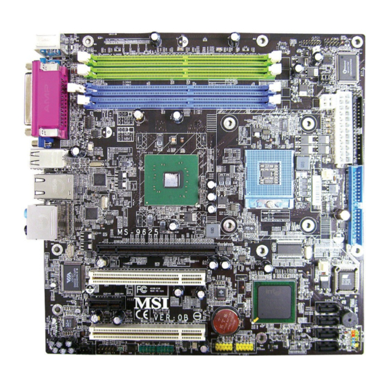
MS-9625 M-ATX Workstation Board Mainboard Layout COM2 JLP C1 Top: Mouse Bottom: Keyboard JCI1 DIMM4 Winbond W83627THF DIMM3 Top : Parallel Port DIMM2 JPW1 Bottom: DIMM1 VGA Port ATX1 USB Ports Intel 915GM CPUFAN1 LAN Jacks Line-In Line-Out T: RS-Out PCI _E1 M: CS-Out B: SPDIFOut... -
Page 15: Msi Special Features
Getting Started MSI Special Features Core Center (Optional) The Core Center is a new utility you can find in the CD-ROM disk. The utility is just like your PC doctor that can detect, view and adjust the PC hardware and system status during real time operation. - Page 16 Here you may adjust the CPU fan speed. If you choose User mode, you may adjust the CPU fan speed in 8 different modes, from Stop to Full speed. MSI Reminds You... Items shown on Core Center may vary depending on your system status.
-
Page 17: Chapter 2. Hardware Setup
Hardware Setup Chapter 2. Hardware Setup Hardware Setup This chapter provides you with the information about hardware setup procedures. W hile doing the installation, be careful in holding the c omponents and follow the installation procedures . For s ome components, if you install in the wrong orientation, the components will not work properly. -
Page 18: Quick Components Guide
MS-9625 M-ATX Workstation Board Quick Components Guide JPW1, p.2-8 COM2, p.2-18 DIMM4/3/2/1, p.2-6 JCI1, p.2-16 J6/J4/J5, I/O Ports, p.2-20/21 p.2-9 ATX1, p.2-8 CPU, p.2-3 FDD1, p.2-13 IDE1, p.2-13 J3, p.2-21 CPUFAN1/ SYSFAN1, p.2-17 B I O S SATA4/ SATA3/ PCI/PCI SATA2/ Express Slots, SATA1, p.2-14... -
Page 19: Central Processing Unit: Cpu
If you do not have the heat sink and cooling fan, contact your dealer to purchase and install them before turning on the computer. For more information on compatible components, please visit http://www.msi.com. tw/program/products/server/svr/pro_svr_qvl.php . MSI Reminds You... -
Page 20: Cpu And Cooler Set Installation
MS-9625 M-ATX Workstation Board CPU & Cooler Set Installation 1. Place the CPU on top of the socket. Make sure to align the gold arrow on the CPU with the arrow key on the socket. 2. Push the CPU down until its pins securely fit into the socket. 3. - Page 21 Hardware Setup 5. Secure one end of the metal clip to the retention mechanism. 6. Hook the other end of the clip to the re- tention mechanism and press the lever down to close. 7. Follow the same procedures to install the second clip.
-
Page 22: Memory
DIMMs) or DDR-II 400/533 (two 240-pin 400/533MHz non-ECC DDR-II DIMMs) system memory. Please note that only one type of memory (all DDR or all DDR-II, no mixture allowed) can be used at one time. For more information on compatible components, please visit http://www.msi.com. tw/program/products/server/svr/pro_svr_qvl.php . DIMM4 (DDR-II 400/533) -
Page 23: Memory Population Rules
DIMM1 or DIMM3 64MB~1GB DIMM2 or DIMM4 64MB~1GB M aximum Sy stem M emory Supported 64MB~2GB S: Single Side D: Double Side MSI Reminds You... Make sure that you install memory modules of the same type and density on DDR DIMMs. -
Page 24: Power Supply
SIGNAL 5VSB +12V +12V MSI Reminds You... 1. Maker sure that these two connectors are connected to adequate SSI power supplies to ensure stable operation of the mainboard. 2. Power supply of 350watts (and above) is highly recommended for system stability. -
Page 25: Back Panel
Hardware Setup Back Panel L-In RS-Out Parallel M ou se L-Out CS-Out COM Port Keyboard VGA Port USB Ports SPDIF Out (Optical) Mouse Connector (Green) / Keyboard Connector (Purple) ® The mainboard provides a standard PS/2 mouse/keyboard mini DIN connector for ®... -
Page 26: Serial Port
MS-9625 M-ATX Workstation Board Serial Port The mainboard offers one 9-pin male DIN connector as the serial port. The port is a 16550A high speed communication port that sends/receives 16 bytes FIFOs. You can attach a serial mouse or other serial devices directly to the connector. Pin Definition 1 2 3 4 5 SIGNAL... -
Page 27: Lan (Rj-45) Jacks
Hardware Setup LAN (RJ-45) Jacks The mainboard provides 2 standard RJ-45 jacks for connection to single Local Area Network (LAN). This Giga-bit LAN enables data to be transferred at 1000, 100 or 10Mbps. You can connect a network cable to either LAN jack. Giga-bit LAN Pin Definition SIGNAL DESCRIPTION... -
Page 28: Parallel Port Connector: Lpt1
MS-9625 M-ATX Workstation Board Parallel Port Connector: LPT1 The mainboard provides a 25-pin female centronic connector as LPT. A parallel port is a standard printer port that supports Enhanced Parallel Port (EPP) and Extended Capabilities Parallel Port (ECP) mode. Pin Definition SIGNAL DESCRIPTION STROBE... -
Page 29: Connectors
IDE1 can connect a Master and a Slave drive. You must configure the second hard drive to Slave mode by setting the jumper accordingly. MSI Reminds You... If you install two hard disks on cable, you must configure the second drive to Slave mode by setting its jumper. -
Page 30: Serial Ata Connectors: Sata1, Sata2, Sata3, Sata4
Take out the dust cover and connect to the hard disk devices Optional Serial ATA cable Connect to SATA1/2/3/4 MSI Reminds You... Please do not fold the Serial ATA cable into 90-degree angle. Otherwise, the loss of data may occur during transmission. 2-14... -
Page 31: Front Panel Audio Connector: Jaud1
Analog Port 2 - Left channel SENSE2_RETIRN Jack detection return from front panel JACK2 MSI Reminds You... If you don’t want to connect to the front audio header, pins 5 & 6, 9 & 10 have to be jumpered in order to have signal output directed to the rear audio ports. -
Page 32: Chassis Intrusion Switch Connector: Jci1
MS-9625 M-ATX Workstation Board Chassis Intrusion Switch Connector: JCI1 This connector is connected to a 2-pin chassis switch. If the chassis is opened, the switch will be short. The system will record this status and show a warning mes- sage on the screen. To clear the warning, you must enter the BIOS utility and clear the record. -
Page 33: Fan Power Connectors: Cpufan1, Sysfan1
+1 2V +1 2V SENSOR SENSOR CPUFAN1 SYSFAN1 MSI Reminds You... ® Please refer to the recommended CPU fans at Intel official website or consult the vendors for proper CPU cooling fan. IEEE 1394 Connectors: J1394_1, J1394_2 The mainboard provides two 1394 pin headers that allow you to connect IEEE 1394 ports via an external IEEE1394 bracket. -
Page 34: Front Usb Connectors: F_Usb1, F_Usb2
USB1+ Key (no pin) USBOC Connect to F_USB1 or F_USB2 (the USB pinheader in YELLOW color) USB 2.0 Bracket (Optional) MSI Reminds You... Note that the pins of VCC and GND must be connected correctly to avoid possible damage. 2-18... -
Page 35: Jumper
CLR_CMOS1 Keep Data Clear Data MSI Reminds You... You can clear CMOS by shorting 2-3 pin while the system is off. Then return to 1-2 pin position. Avoid clearing the CMOS while the system is on; it will damage the mainboard. -
Page 36: Fsb Frequency Jumpers: J4, J5
MS-9625 M-ATX Workstation Board FSB Frequency Jumpers: J4, J5 These two jumpers specify the FSB frequency of the onboard CPU. To ensure system stability, make sure that these jumpers are properly set to correspond with your CPU’s FSB frequency. Dothan B Dothan A FSB400 Dothan A FSB533 2-20... -
Page 37: Cpu Vcca Jumper: J6
Hardware Setup CPU VCCA Jumper: J6 This jumper controls the CPU VCCA supply voltage. VCCA = 1.8V VCCA = 1.5V GMCH Voltage Jumper: J3 This jumper is used to adjust the voltage of the Intel 915GM GMCH (Graphics and Memory Controller Hub) as a way to enhance graphics performance. } 1.05V for add-on VGA card } 1.05V for onboard Intel 915GM Short Pin #1-2... -
Page 38: Slots
MS-9625 M-ATX Workstation Board Slots The motherboard provides one PCI Express x1 slot, one PCI Express x16 slot, and two 32-bit/33MHz PCI slots. PCI (Peripheral Component Interconnect) Express Slots The PCI Express slots support high-bandwidth, low pin count, and serial interconnect technology. -
Page 39: Pci Interrupt Request Routing
Hardware Setup PCI Interrupt Request Routing The IRQ, acronym of interrupt request line and pronounced I-R-Q, are hardware lines over which devices can send interrupt signals to the microprocessor. The PCI IRQ pins are typically connected to the PCI bus pins as follows: DEVICE ICH INT Pin IDSEL... -
Page 40: Chapter 3. Bios Setup
SETUP. ² You want to change the default settings for customized features. MSI Reminds You... 1. The items under each BIOS category described in this chapter are under continuous update for better system performance. -
Page 41: Entering Setup
MS-9625 M-ATX Workstation Board Entering Setup Power on the computer and the system will start POST (Power On Self Test) process. W hen the message below appears on the screen, press <F1> key to enter Setup. Press F1 to enter SETUP If the message disappears before you respond and you still wish to enter Setup, restart the system by turning it OFF and On or pressing the RESET button. -
Page 42: Getting Help
BIOS Setup Getting Help After entering the Setup menu, the first menu you will see is the Main Menu. M ain M enu The main menu lists the setup functions you can make changes to. You can use the arrow keys ( ↑↓ ) to select the item. The on-line description of the highlighted setup function is displayed at the bottom of the screen. -
Page 43: The Menu Bar
MS-9625 M-ATX Workstation Board The Menu Bar Once you enter Phoenix-AwardBIOS CM OS Setup Utility, the Main Menu will appear on the screen. On the Main Menu screen, you will see basic BIOS settings including system time & date, and the setup categories the BIOS supplies. Use Arrow keys to move among the items and menus, and make changes to the settings. -
Page 44: Main
BIOS Setup Main The items inside the Main menu are for basic system information and configuration. Each item includes none, one or more setup items. Use the Up/Down arrow keys or <Tab> to highlight the item or field you want to modify and use the <+> or <-> key to switch to the value you prefer. -
Page 45: Advanced
MS-9625 M-ATX Workstation Board Advanced Items in the menu are divided into several sub-menus. Each sub-menu provides more settings. To enter the sub-menu, highligh the sub-menu you want to configure and press <Enter>. Advanced Chipset Features The sub-menu is used to configure chipset features for optimal system performance. - Page 46 BIOS Setup DRAM Timing Selectable Selects whether DRAM timing is controlled by the SPD (Serial Presence Detect) EEPROM on the DRAM module. Setting to [By SPD] enables DRAM timing to be determined automatically by BIOS based on the configurations on the SPD. Selecting [Manual] allows users to configure the following fields manually.
- Page 47 MS-9625 M-ATX Workstation Board Integrated Peripherals Press <Enter> to enter the sub-menu and the following screen appears: OnChip IDE Device Press <Enter> to enter the sub-menu and the following screen appears: On-Chip Serial ATA This setting specifies the function of the on-chip SATA controller. [Disabled] Disable SATA controller [Enhanced Mode]...
- Page 48 BIOS Setup PATA IDE Mode / SATA Port These settings show the modes of the PATA & SATA ports. Onboard Device Press <Enter> to enter the sub-menu and the following screen appears: Onboard LAN 1, Onboard LAN 2, PCI-E X1 Slot These settings control the onboard LAN 1, LAN 2, and PCI-Express X1 slot controllers.
- Page 49 MS-9625 M-ATX Workstation Board Azalia/AC97 Audio Select Azalia is the codename of “High Definition Audio.” This setting allows users to disable/enable the High Definition Audio interface integrated in ICH6 / ICH6R southbridge. Onboard 1394 Device This setting is used to enable/disable the onboard IEEE 1394 controller. Setting options: [Disabled], [Enabled].
- Page 50 BIOS Setup SPP: Standard Parallel Port EPP: Enhanced Parallel Port ECP: Extended Capability Port Setting options: [SPP], [EPP], [ECP], [ECP+EPP], [Normal]. EPP M ode Select The onboard parallel port is EPP Spec. compliant, so after the user chooses the onboard parallel port with the EPP function, the following message will be displayed on the screen: “EPP Mode Select.”...
- Page 51 MS-9625 M-ATX Workstation Board ACPI Function This item is to activate the ACPI (Advanced Configuration and Power Manage- ment Interface) Function. If your operating system is ACPI-aware, such as W indows 98SE/2000/ME, select [Enabled]. Settings: [Enabled] and [Disabled]. ACPI Suspend Type This item specifies the power saving modes for ACPI function.
- Page 52 BIOS Setup PC Health Status Press <Enter> to enter the sub-menu and the following screen appears: Smart SYSFan1/CPUFan1 Temperature, SYSFan1/CPUFan1 Tolerance Value, Current Sy stem/CPU Temperature, System Fan1/CPU Fan1 Speed, Vcore, VCC3, VCC_DDR, 12V, VCC (V), VBAT (V), 5VSB (V) These items display the current status of all of the monitored hardware de- vices/components such as CPU voltage, temperatures and all fans’...
- Page 53 EMI generated by modulating the pulses so that the spikes of the pulses are reduced to flatter curves. MSI Reminds You... 1. If you do not have any EMI problem, leave the setting at [Disabled] for optimal system stability and performance. But if you are plagued by EMI, select the value of Spread Spectrum for EMI reduction.
- Page 54 BIOS Setup 2. The greater the Spread Spectrum value is, the greater the EMI is reduced, and the system will become less stable. For the most suitable Spread Spectrum value, please consult your local EMI regulation. 3. Remember to disable Spread Spectrum if you are overclocking because even a slight jitter can introduce a temporary boost in clock speed which may just cause your overclocked processor to lock up.
-
Page 55: Security
MS-9625 M-ATX Workstation Board Security This section lets you set security passwords to control access to the system at boot time and/or when entering the BIOS setup program. Set Supervisor Password Use this menu to set Supervisor Password. Set User Password Use this menu to set User Password. -
Page 56: Server
BIOS Setup Server This section shows the overall hardware specifications of your system. System Summary Press <Enter> to view the hardware specifications of your system. 3-17... - Page 57 MS-9625 M-ATX Workstation Board Small Logo(EPA) Show This item enables you to show the EPA logo (brand specific graphics) on the bootup screen. Settings are: [Disabled] Shows the normal POST screen at boot. [Enabled] Shows a still image (EPA logo) on the screen at boot.ot. Halt On The setting determines whether the system will stop if an error is detected at boot.
-
Page 58: Boot
BIOS Setup Boot Use this menu to arrange and specify the priority of the devices from which the BIOS will attempt to boot the Operating System. Removable Device Priority, Hard Disk Boot Priority, CD-ROM Boot Priority These settings allow users to set the priority of the specified devices. First press <Enter>... -
Page 59: Exit
MS-9625 M-ATX Workstation Board Exit The following sections describe each of the options on this menu. Note that <Esc> does not exit this menu. You must select one of the items from the menu or menu bar to exit. Load Fail-Safe Defaults Use this menu to load the default values set by the BIOS vendor for stable system performance. -
Page 60: Appendix A: Realtek Alc880 8-Channel Audio Function
Realtek ALC880 8-Channel Audio Function Appendix A: Realtek ALC880 8-Chan- nel Audio Function The mainboard is equipped with Realtek ALC880 chip, which provides support for 8-channel audio output, including 2 Front, 2 Rear, 1 Center and 1 Subwoofer channel. ALC880 allows the board to attach 2, 4, 6 or 8 speakers for better surround sound effect. -
Page 61: Installing The Realtek Hd Audio Driver
1. Insert the companion CD into the CD-ROM drive. The setup screen will auto- matically appear. 2. Click Realtek HD Audio Driver. Click here MSI Reminds You... The HD Audio Configuration software utility is under continuous update to enhance audio application. Hence, the program screens shown here in this appendix may be slightly different from the latest software utility and shall be held for reference only. - Page 62 Realtek ALC880 8-Channel Audio Function 3. Click Next to install the Realtek High Definition Audio Driver. Click here 4. Click Finish to restart the system. Select this option Click here...
-
Page 63: Software Configuration
MS-9625 M-ATX Workstation Board Software Configuration After installing the audio driver, you are able to use the 2-, 4-, 6- or 8- channel audio feature now. Click the audio icon from the system tray at the lower-right corner of the screen to activate the HD Audio Configuration. It is also available to enable the audio driver by clicking the Azalia HD Sound Effect M anager from the Control Panel. -
Page 64: Sound Effect
Realtek ALC880 8-Channel Audio Function Sound Effect Here you can select a sound effect you like from the Environment list. Load EQ Setting Reset EQ Setting EQ Setting On/Off Save Preset Delete EQ Setting You may choose the provided sound effects, and the equalizer will adjust automatically. If you like, you may also load an equalizer setting or make an new equalizer setting to save as an new one by using the “Load EQ Setting”... - Page 65 MS-9625 M-ATX Workstation Board Equalizer Selection Equalizer frees users from default settings; users may create their own preferred settings by utilizing this tool. 10 bands of equalizer, ranging from 100Hz to 16KHz. Save Reset The settings are 10 bands of equalizer saved permanently for would go back to the future use...
- Page 66 Realtek ALC880 8-Channel Audio Function Frequently Used Equalizer Setting Realtek HD Audio Sound Manager provides you certain optimized equalizer settings that are frequently used for your quick enjoyment. [How to Use It] Other than the buttons “Pop” “Live” “Club” & “Rock” shown on the page, to pull down the arrow in “Others”...
-
Page 67: Mixer
Realtek HD Audio rear output or Realtek HD Audio front output items. MSI Reminds You... Before set up, please make sure the playback devices are well plugged in the jacks on the rear or front panel. The Realtek HD Audio front output item will appear after you pluging the speakers into the jacks on the front panel. - Page 68 Realtek ALC880 8-Channel Audio Function W hen you are playing the first audio source (for example: use W indows Media Player to play DVD/VCD), the output will be played from the rear panel, which is the default setting. Then you must to select the Realtek HD Audio front output from the scroll list first, and use a different program to play the second audio source (for example: use W inamp to play MP3 files).
- Page 69 MS-9625 M-ATX Workstation Board 3. Playback control Tool Mute Playback device This function is to let you freely decide which ports to output the sound. And this is essential when multi- streaming playback enabled. M u te You may choose to mute single or multiple volume controls or to completely mute sound output.
- Page 70 Realtek ALC880 8-Channel Audio Function 4. Recording control Recording device Tool Back Line In/Mic, Front Line In Realtek HD Audio Digital Input Tool Show the following volume controls This is to let you freely decide which volume control items to be displayed. Advanced controls.
- Page 71 You may control the microphone volume by M ic Volume or front mic-in on the mixer. MSI Reminds You... Only the speakers that plugged into the Line-Out jack (the green ne) on the back panel will be functional when you intend to listen to the audio that has been recorded from the microphone.
-
Page 72: Audio I/O
Realtek ALC880 8-Channel Audio Function Audio I/O In this tab, you can easily configure your multi-channel audio function and speakers. You can choose a desired multi-channel operation here. a. Headphone for the common headphone b. 2CH Speaker for Stereo-Speaker Output c. - Page 73 MS-9625 M-ATX Workstation Board Correct M essage Assume to plug a headphone in the Green jack at back panel. The icon beside green jack become visible and the dialogue “connected device” pops up. Check the headphone, then click OK. As soon as OK is clicked, the icon beside green jack becomes “headphone”...
- Page 74 Realtek ALC880 8-Channel Audio Function Global Connector Settings Click to access global connector settings. 1. M ute rear panel output when front headphone plugged in Once this item is checked, whenever front headphone is plugged, the music that is playing from the back panel, will be stopped. 2.
- Page 75 MS-9625 M-ATX Workstation Board S/PDIF Short for Sony/Philips Digital Interface, a standard audio file transfer format. S/PDIF allows the transfer of digital audio signals from one device to another without having to be converted first to an analog format. Maintaining the viability of a digital signal pre- vents the quality of the signal from degrading when it is converted to analog.
- Page 76 Realtek ALC880 8-Channel Audio Function Test Speakers You can select the speaker by clicking it to test its functionality. The one you select will light up and make testing sound. If any speaker fails to make sound, then check whether the cable is inserted firmly to the connector or replace the bad speakers with good ones.
-
Page 77: Microphone
MS-9625 M-ATX Workstation Board Microphone In this tab you may set the function of the microphone. Select the Noise Suppres- sion to remove the possible noise during recording, or select Acoustic Echo Cancelltion to cancel the acoustic echo druing recording. Also, please use the drop-down list to choose the recording source from Realtek HD Audio real input or Realtek HD Audio front input. -
Page 78: 3D Audio Demo
Realtek ALC880 8-Channel Audio Function 3D Audio Demo In this tab you may adjust your 3D positional audio before playing 3D audio applica- tions like gaming. You may also select different environment to choose the most suitable environment you like. A-19... -
Page 79: Information
MS-9625 M-ATX Workstation Board Information In this tab it provides some information about this HD Audio Configuration utility, including Audio Driver Version, DirectX Version, Audio Controller & Audio Codec. You may also select the language of this utility by choosing from the Language list. Also there is a selection Show icon in system tray. - Page 80 Realtek ALC880 8-Channel Audio Function Before you begin using the front panel function, please complete the following steps: 1. Please install the pinheaders of the front panel according to Chapter 2. 2. Select AC97 or Azalia in the BIOS setting (Chapter 3). 3.
-
Page 81: Using 2-, 4-, 6- & 8- Channel Audio Function
MS-9625 M-ATX Workstation Board Using 2-, 4-, 6- & 8- Channel Audio Function Connecting the Speakers W hen you have set the Multi-Channel Audio Function mode properly in the software utility, connect your speakers to the correct phone jacks in accordance with the setting in software utility. - Page 82 Realtek ALC880 8-Channel Audio Function n 4-Channel M ode for 4-Speaker Output Back Panel Description: Connect two speakers to back panel’s Line Out connector and two speakers to the real-chan- nel Line Out connector. 4-Channel Analog Audio Output Line In Line Out (Front channels) Line Out (Rear channels) Line Out (Center and Subwoofer channel, but no functioning in this mode)
- Page 83 MS-9625 M-ATX Workstation Board n 6-Channel M ode for 6-Speaker Output Back Panel Description: Connect two speakers to back 6-Channel Analog Audio Output panel’s Line Out connector, two speakers to the rear-channel and two speakers to the cen- Line In ter/subwoofer-channel Line Out Line Out (Front channels) connectors.
- Page 84 Realtek ALC880 8-Channel Audio Function n 8-Channel M ode for 8-Speaker Output Back Panel Description: Connect two speakers to back panel’s Line Out connector, two speakers to the rear-channel, two speakers to the c enter/ 8-Channel Analog Audio Output subwoofer-channel Line Out connectors, and two speakers to the side-channel Line Out Line Out (Side channels)
-
Page 85: Appendix B: Intel Ich6R Sata Raid (Optional
Intel Matrix RAID Technology is the advanced ability for two RAID volumes to share the combined space of two hard drives being used in unison. MSI Reminds You... The maximum number of hard drives for RAID 0, RAID 1 or Matrix mode is 2. -
Page 86: Bios Configuration
Intel RAID Option ROM. During the Power-On Self Test (POST), the following message will appear for a few seconds: MSI Reminds You... The “Driver Model”, “Serial #” and “Size” in the following example might be different from your system. - Page 87 Intel ICH6R SATA RAID After pressing the <Ctrl> and <I> keys simultaneously, the following window will appear: (1) Create RAID Volume Select option 1 “Create RAID Volume” and press <Enter> key. The following screen appears. Then in the Name field, specify a RAID Volume name and then press the <TAB>...
- Page 88 MS-9625 M-ATX Workstation Board In the Disk field, press <Enter> key and the following screen appears. Use <Space> key to select the disks you want to create for the RAID volume, then click <Enter> key to finish selection. Then select the strip value for the RAID 0 or RAID 1 array by using the “upper arrow”...
- Page 89 Intel ICH6R SATA RAID MSI Reminds You... Since you want to create two volumes (Intel Matrix RAID Technology), this default size (maximum) needs to be reduced. Type in a new size for the first volume. As an example: if you want the first volume to span the first half of the two disks, re-type the size to be half of what is shown by default.
- Page 90 Here you can delete the RAID volume, but please be noted that all data on RAID drives will be lost. MSI Reminds You... If your system currently boots to RAID and you delete the RAID volume in the Intel RAID Option ROM, your system will become unbootable.
- Page 91 RAID volume and remove any RAID structures from the drives. The following screen appears: Press <Y> key to accept the selection. MSI Reminds You... 1. You will lose all data on the RAID drives and any internal RAID structures when you perform this operation.
-
Page 92: Installing Software
Windows XP/2000 installation. † Existing Windows XP/2000 Driver Installation 1. Insert the MSI CD into the CD-ROM drive. 2. The CD will auto-run and the setup screen will appear. 3. Under the Driver tab, click on Intel IAA RAID Edition. -
Page 93: Installation Of Intel Application Accelerator Raid Edition
For this reason, you cannot remove or un-install this driver from the system after installation; however, you will have the ability to un-install all other non-driver components. Insert the MSI CD and click on the Intel IAA RAID Edition to install the software. Click on this item... - Page 94 MS-9625 M-ATX Workstation Board The InstallShield Wizard will begin automatically for installation showed as following: Click on the Next button to proceed the installation in the welcoming window. B-10...
- Page 95 Intel ICH6R SATA RAID The window shows the components to be installed. Click Next button to continue. After reading the license agreement in the following window, click Yes button to continue. B-11...
- Page 96 MS-9625 M-ATX Workstation Board Select the folder in which you want the program to be installed in the following window, and click Next button to start installation. Select a program folder in the following window where you want Setup to add the program icon.
- Page 97 Intel ICH6R SATA RAID The following window appears to show the Intel Application Accelerator RAID Edition Setup installation status. Once the installation is complete, the following window appears. B-13...
-
Page 98: Raid Migration Instructions
To create a volume from an existing disk, complete the following steps: MSI Reminds You... A Create from Existing Disk operation will delete all existing data from the added disk and the data cannot be recovered. It is critical to backup all important data on the added disk before proceeding. -
Page 99: Create Raid Volume From Existing Disk
Intel ICH6R SATA RAID Create RAID Volume from Existing Disk To create a RAID volume from an existing disk, choose Action --> Create RAID Volume from Existing Hard Drive. The Create RAID Volume from Existing Hard Drive Wizard pops up to lead you for the following procedure. - Page 100 MS-9625 M-ATX Workstation Board (1) Step 1: Configure Volume Here you can configure the new RAID volume by entering the volume name, selecting the RAID level and strip size. † RAID Volume Name: A desired RAID volume name needs to be typed in where the ‘RAID_Volume1’ text currently appears above.
- Page 101 Intel ICH6R SATA RAID (2) Select the source disk Then select the source disk that you wish to use and then click “--->” to move it to the Selected field. Then click Next to continue. It is very important to note which disk is the source disk (the one containing all of the information to be migrated) and which one is the target disk.
- Page 102 MS-9625 M-ATX Workstation Board (3) Select M ember Hard Drive(s) Then select the member disk (the target disk) that you wish to use and then click “--->” to move it to the Selected field. Then click Next to continue. Please note that the existing data on the selected hard drive(s) will be deleted permanently.
- Page 103 Intel ICH6R SATA RAID (4) Specify Volume Size Specify the amount of available array space to be used by the new RAID volume. You may enter the amount in the space or use the slider to specify. It is recommended you use 100% of the available space for the optimized usage, either for RAID 0 or RAID1 volume.
- Page 104 MS-9625 M-ATX Workstation Board (6) Start Migration The migration process may take up to two hours to complete depending on the size of the disks being used and the strip size selected. A dialogue window will appear stating that the migration process may take considerable time to complete, meanwhile a popup dialogue at the taskbar will also show the migration status.
Need help?
Do you have a question about the 915GM Speedster MS-9625 and is the answer not in the manual?
Questions and answers