Table of Contents
Advertisement
Advertisement
Chapters
Table of Contents

Related Manuals for MSI MS-98F6


Summary of Contents for MSI MS-98F6
- Page 1 MS-98F6 (v1.x) Industrial Computer Board...
-
Page 2: Revision History
If a problem arises with your system and no solution can be obtained from the user’s manual, please contact your place of purchase or local distributor. Alternatively, please visit the MSI website for technical guide, BIOS updates, driver updates and other information, or contact our technical staff via http://www. -
Page 3: Safety Instructions
MS-98F6 Safety Instructions ■ Always read the safety instructions carefully. ■ Keep this User’s Manual for future reference. ■ Keep this equipment away from humidity. ■ Lay this equipment on a reliable flat surface before setting it up. ■ The openings on the enclosure are for air convection hence protects the equipment from overheating. -
Page 4: Chemical Substances Information
Chemical Substances Information In compliance with chemical substances regulations, such as the EU REACH Regulation (Regulation EC No. 1907/2006 of the European Parliament and the Council), MSI provides the information of chemical substances in products at: http://www.msi.com/html/popup/csr/evmtprtt_pcm.html Battery Information European Union: Batteries, battery packs, and accumulators should not be disposed of as unsorted household waste. -
Page 5: Ce Conformity
MSI will comply with the product take back requirements at the end of life of MSI-branded products that are sold into the EU. You can return these products to local collection points. -
Page 6: Table Of Contents
Preface CONTENTS Copyright Notice .................... ii Trademarks ....................ii Revision History .................... ii Technical Support ..................ii Safety Instructions ..................iii Chemical Substances Information ............... iv Battery Information ..................iv CE Conformity ....................v FCC-A Radio Frequency Interference Statement ......... v WEEE Statement .................. -
Page 7: Overview
Overview Thank you for choosing the MS-98F6, an excellent industrial computer board. With low power and low profile design, the MS-98F6 accommodates the Intel Celeron J1900/ N2930 Processor and supports up to 1 DDR3L ® ® 1333 MHz SO-DIMM slots to provide the maximum of 8GB memory capacity. -
Page 8: Motherboard Specifications
Overview Motherboard Specifications Processor ■ Intel Celeron J1900/ N2930 Processor Memory ■ 1 x DDR3L 1333 MHz SO-DIMM slot ■ Supports the maximum of 8GB ■ 2 x Intel I210-AT GbE LAN SATA ■ 1 x SATA 3Gb/s port ■ 1 x mSATA slot (shared with Mini-PCIe slot) Audio ■... - Page 9 MS-98F6 Onboard Pin Headers/ Connectors/ Jumpers ■ 1 x SATA connector ■ 1 x SATA power connector ■ 2 x USB2.0 headers ■ 1 x 8-bit GPIO header ■ 6 x COM port headers ■ 1 x Front panel connector ■...
-
Page 10: Motherboard Layout
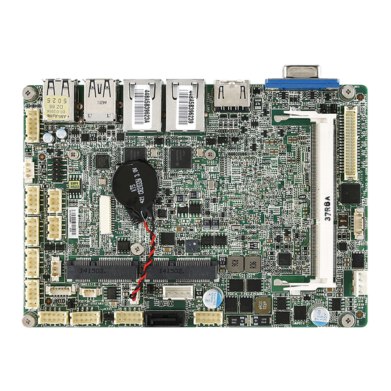
Overview Motherboard Layout LVDS Connector LVDS Inverter LVDS Inverter Connector Power Jumper SO-DIMM Slot DC-In 12V/19V/24V LVDS Power Power Connector Jumper Back Panel Mini-PCIe Slot Mini-PCIe/mSATA Slot TXE F/W Jumper LAN1 Jumper GPIO Pin Connector SATA Power Connector LAN2 Jumper SATA 2.0 Port Clear CMOS Jumper Front Panel... -
Page 11: Me Overview
MS-98F6 ME Overview Board Dimension unit of measurement: mm... - Page 12 Overview Suggested Chassis I/O Gap Dimension...
-
Page 13: Hardware Setup
Hardware Setup This chapter provides you with the information about hardware setup procedures. While doing the installation, be careful in holding the components and follow the installation procedures. For some components, if you install in the wrong orientation, the components will not work properly. - Page 14 Hardware Setup Components Reference Guide Memory ....................2-3 Power Supply ..................2-4 DC Power Connector: JPWR2 ..............2-4 SATA Power Connector: JPW1 ..............2-4 Rear Panel I/O ...................2-5 Connector ..................2-7 Fan Power Connector: SYSFAN1 ..............2-7 GPIO Pin Header: JGPIO1 ................2-8 Serial ATA Connector: SATA1 ..............2-8 Front Panel Connector: JFP1 ..............2-9 LPC Debug Port Connector: JDP1 .............2-9 USB 2.0 Connector: JUSB1, JUSB2 ............2-10...
-
Page 15: Memory
MS-98F6 Memory The SO-DIMM slot is intended for memory modules. 1. Locate the SO-DIMM slot. Align the notch on the DIMM with the key on the slot and insert the DIMM into the slot. 2. Push the DIMM gently downwards until the slot levers click and lock the DIMM in place. -
Page 16: Power Supply
Hardware Setup Power Supply DC Power Connector: JPWR2 This connector allows you to connect a 12V/ 19V/ 24V DC power adapter. SATA Power Connector: JPW1 This connector is used to provide power to SATA devices. Important Make sure that all power connectors are connected to the power supply to ensure stable operation of the motherboard. -
Page 17: Rear Panel I/O
MS-98F6 Rear Panel I/O USB 2.0 USB 2.0 Port Port USB 3.0 USB 2.0 VGA Port HDMI Port Port Port Port Port VGA Port The DB15-pin female connector is provided for monitor. HDMI Port The High-Definition Multimedia Interface (HDMI) is an all-digital audio-video interface that is capable of transmitting uncompressed streams. - Page 18 Hardware Setup USB 2.0 Port The USB (Universal Serial Bus) port is for attaching USB devices such as keyboard, mouse, or other USB-compatible devices. USB 3.0 Port The USB 3.0 port is backward-compatible with USB 2.0 devices and supports data transfer rate up to 5 Gbit/s (SuperSpeed).
-
Page 19: Connector
MS-98F6 Connector Fan Power Connector: SYSFAN1 The fan power connectors support system cooling fan with +12V. When connecting the wire to the connectors, always note that the red wire is the positive and should be connected to the +12V; the black wire is Ground and should be connected to GND. -
Page 20: Gpio Pin Header: Jgpio1
Hardware Setup GPIO Pin Header: JGPIO1 This connector is provided for the General-Purpose Input/Output (GPIO) peripheral module. Serial ATA Connector: SATA1 This connector is a high-speed Serial ATA interface port. Each connector can connect to one Serial ATA device. Important Please do not fold the SATA cable into a 90-degree angle. -
Page 21: Front Panel Connector: Jfp1
MS-98F6 Front Panel Connector: JFP1 This front panel connector is provided for electrical connection to the front panel switches & LEDs and is compliant with Intel Front Panel I/O Connectivity Design Guide. LPC Debug Port Connector: JDP1 This connectoris LPC debug port. -
Page 22: Usb 2.0 Connector: Jusb1, Jusb2
Hardware Setup USB 2.0 Connector: JUSB1, JUSB2 This connector, compliant with Intel I/O Connectivity Design Guide, is ideal for connecting high-speed USB interface peripherals such as USB HDD, digital cameras, MP3 players, printers, modems and the like. Important Note that the pins of VCC and GND must be connected correctly to avoid pos- sible damage. - Page 23 MS-98F6 RS-232 SIGNAL DESCRIPTION Data Carrier Detect Receive Data Transmit Data Data Terminal Ready Signal Ground Data Set Ready Request To Send Clear To Send VCC_COM1 Voltage select setting by JCOMP1 RS-422 SIGNAL DESCRIPTION 422 TXD- Transmit Data, Negative 422 RXD+...
-
Page 24: Lvds Inverter Connector: Jinvdd1
Hardware Setup LVDS Inverter Connector: JINVDD1 The connector is provided for LCD backlight options. LVDS Connector: JLVDS1 The LVDS (Low Voltage Differential Signal) connector provides a digital interface typically used with flat panels. After connecting an LVDS interface flat panel to the JLVDS1, be sure to check the panel datasheet and set the LVDS jumper to proper power voltage. -
Page 25: Audio Amplifier Pinheader: Jamp1
MS-98F6 Audio Amplifier Pinheader: JAMP1 The JAMP1 is used to connect audio amplifiers to enhance audio performance. Front Audio Connector: JAUD1 This connector allows you to connect the front panel audio and is compliant with Intel Front Panel I/O Connectivity Design Guide. -
Page 26: Ps/2 Keyboard/Mouse Connector: Jkbms1
Hardware Setup PS/2 Keyboard/Mouse Connector: JKBMS1 This connector is provided to connect a keyboard and a mouse. I2C Bus Connector: JSMB1 This connector, known as I2C, is for users to connect System Management Bus (SMBus) interface. 2-14... -
Page 27: Jumper
MS-98F6 Jumper Important Avoid adjusting jumpers when the system is on; it will damage the motherboard. Clear CMOS Jumper: JCMOS1 There is a CMOS RAM onboard that has a power supply from an external battery to keep the data of system configuration. With the CMOS RAM, the system can automatically boot OS every time it is turned on. -
Page 28: Serial Port Power Jumper: Jcomp1~3
Hardware Setup Serial Port Power Jumper: JCOMP1~3 This jumper specifies the operation voltage of the COM serial port. JCOMP1~2 JCOMP1 for COM1~2 JCOMP2 for COM3~4 JCOMP3 for COM5~6 +12V JCOMP3 +12V LAN Configure Jumper: JLAN1~2 Use this jumper to specify the operation for LAN. On: Enable security Off: Disable security and and the INVM lock. -
Page 29: Lvds Power Jumper: Jvdd1
MS-98F6 LVDS Power Jumper: JVDD1 Use this jumper to specify the operation voltage of the LVDS interface flat panel. LVDS Inverter Power Jumper: JINV1 Use this jumper to specify the operation voltage of the interver interface flat panel. TXE F/W Jumper: JME1 This jumper is used to enable/disable the Intel TXE F/W. -
Page 30: Slot
Hardware Setup Slot Mini-PCIe (Peripheral Component Interconnect Express) Slot The Mini-PCIe slot is provided for 3G module, wireless LAN card, TV tuner card, Robson NAND Flash card and mSATA devices. Important • MINI_PCIE2 does not support mSATA function. • When adding or removing expansion cards, make sure that you unplug the power supply first. -
Page 31: Bios Setup
BIOS Setup This chapter provides information on the BIOS Setup program and allows users to configure the system for optimal use. Users may need to run the Setup program when: ■ An error message appears on the screen at system startup and re- quests users to run SETUP. -
Page 32: Entering Setup
BIOS Setup Entering Setup Power on the computer and the system will start POST (Power On Self Test) process. When the message below appears on the screen, press <DEL> or <F2> key to enter Setup. Press <DEL> or <F2> to enter SETUP If the message disappears before you respond and you still wish to enter Setup, restart the system by turning it OFF and On or pressing the RESET button. - Page 33 MS-98F6 Control Keys ← → Select Screen ↑ ↓ Select Item Enter Select Change Option General Help Previous Values Optimized Defaults Save & Exit Exit Getting Help After entering the Setup menu, the first menu you will see is the Main Menu.
-
Page 34: The Menu Bar
BIOS Setup The Menu Bar ▶ Main Use this menu for basic system configurations, such as time, date, etc. ▶ Advanced Use this menu to set up the items of special enhanced features. ▶ Boot Use this menu to specify the priority of boot devices. ▶... -
Page 35: Main
MS-98F6 Main ▶ System Date This setting allows you to set the system date. The date format is <Day>, <Month> <Date> <Year>. ▶ System Time This setting allows you to set the system time. The time format is <Hour> <Min- ute>... -
Page 36: Advanced
BIOS Setup Advanced ▶ Bootup NumLock State This setting is to set the Num Lock status when the system is powered on. Setting to [On] will turn on the Num Lock key when the system is powered on. Setting to [Off] will allow users to use the arrow keys on the numeric keypad. - Page 37 MS-98F6 ▶ Super IO Configuration ▶ Serial Port 1/ 2/ 3/ 4/ 5/ 6 This setting enables/disables the specified serial port. ▶ Change Settings This setting is used to change the address & IRQ settings of the specified serial port.
- Page 38 BIOS Setup ▶ H/W Monitor These items display the current status of all monitored hardware devices/ components such as voltages, temperatures and all fans’ speeds. ▶ Smart Fan Configuration ▶ Smart FAN1 Function These settings enable/disable the Smart Fan function. Smart Fan is an excel- lent feature which will adjust the CPU/system fan speed automatically de- pending on the current CPU/system temperature, avoiding the overheating to damage your system.
- Page 39 MS-98F6 ▶ Min. Speed (%) This setting selects the minimum percentage of 12V that the fan needs to start spinning. ▶ CPU Configuration ▶ Active Processor Cores This item allows you to select the number of active processor cores. ▶ Execute Disable Bit Intel’s Execute Disable Bit functionality can prevent certain classes of mali-...
- Page 40 BIOS Setup ▶ PCI/PCIE Device Configuration ▶ PCI Latency Timer This item controls how long each PCI device can hold the bus before another takes over. When set to higher values, every PCI device can conduct trans- actions for a longer time and thus improve the effective PCI bandwidth. For better PCI performance, you should set the item to higher values.
- Page 41 MS-98F6 ▶ Audio Controller This setting enables/disables the onboard audio controller. ▶ Launch OnBoard LAN OpROM These settings enable/disable the initialization of the onboard/onchip LAN Boot ROM during bootup. Selecting [Disabled] will speed up the boot proc- ess. ▶ GPIO Group Configuration ▶...
-
Page 42: Boot
BIOS Setup Boot ▶ CSM Support This setting enables/disables the support for Compatibility Support Module, a part of the Intel Platform Innovation Framework for EFI providing the capability to support legacy BIOS interfaces. Important If the Operating System is going to boot in UEFI mode, disable CSM Support to speed up the boot process. -
Page 43: Security
MS-98F6 Security ▶ Administrator Password Administrator Password controls access to the BIOS Setup utility. ▶ User Password User Password controls access to the system at boot and to the BIOS Setup utility. 3-13... - Page 44 BIOS Setup ▶ Serial Port Console Redirection ▶ Console Redirection Console Redirection operates in host systems that do not have a monitor and keyboard attached. This setting enables/disables the operation of console re- direction. When set to [Enabled], BIOS redirects and sends all contents that should be displayed on the screen to the serial COM port for display on the terminal screen.
- Page 45 MS-98F6 ▶ Terminal Type To operate the system’s console redirection, you need a terminal supporting ANSI terminal protocol and a RS-232 null modem cable connected between the host system and terminal(s). This setting specifies the type of terminal device for console redirection.
- Page 46 BIOS Setup ▶ Security Configuration ▶ Intel(R) TXE Configuration Intel Trusted Execution Technology provides highly scalable platform security in physical and virtual infrastructures. ▶ Intel(R) Anti-Theft Technology Configuration Intel Anti-Theft Technology is hardware-based technology that can lock a lost or stolen system so that personal confidential information is protected and inaccessible by unauthorized users.
-
Page 47: Chipset
MS-98F6 Chipset ▶ DVMT Pre-Allocated This setting defines the DVMT pre-allocated memory. Pre-allocated memory is the small amount of system memory made available at boot time by the system BIOS for video. Pre-allocated memory is also known as locked memory. This is because it is "locked"... -
Page 48: Power
BIOS Setup Power ▶ Restore AC Power Loss This setting specifies whether your system will reboot after a power failure or interrupt occurs. Available settings are: [Power Off] Leaves the computer in the power off state. [Power On] Leaves the computer in the power on state. [Last State] Restores the system to the previous status before power failure or interrupt occurred. - Page 49 MS-98F6 ** Advanced Resume Events Control ** ▶ PCIE PME This field specifies whether the system will be awakened from power saving modes when activity or input signal of onboard PCIE PME is detected. ▶ USB from S3/S4 The item allows the activity of the USB device to wake up the system from S3/S4 sleep state.
-
Page 50: Save & Exit
BIOS Setup Save & Exit ▶ Save Changes and Reset Save changes to CMOS and reset the system. ▶ Discard Changes and Exit Abandon all changes and exit the Setup Utility. ▶ Discard Changes Abandon all changes. ▶ Restore Defaults Use this menu to load the default values set by the motherboard manufacturer specifically for optimal performance of the motherboard. -
Page 51: Appendix Wdt & Gpio
Appendix WDT & GPIO This appendix provides the sample codes of WDT (Watch Dog Timer) and GPIO (General Purpose Input/ Output). 2-A-1... -
Page 52: Wdt Sample Code
WDT & GPIO WDT Sample Code SIO_INDEX_Port equ 04Eh SIO_DATA_Port equ 04Fh SIO_UnLock_Value equ 087h SIO_Lock_Value equ 0AAh WatchDog_LDN equ 007h WDT_UNIT equ 60h ;60h=second, 68h=minute, 40h=Disabled Watchdog timer WDT_Timer equ 30 ;ex. 30 seconds Sample code: ;Enable config mode dx, SIO_INDEX_Port al, SIO_UnLock_Value dx, al... -
Page 53: Gpio Sample Code
MS-98F6 GPIO Sample Code GPI 0 ~ GPI 3 GPI 0 GPI 1 GPI 2 GPI 3 IO Address SIO GPIO Register Sample code GPO 0 ~ GPO 3 GPO 0 GPO 1 GPO 2 GPO 3 IO Address... - Page 54 dx, SIO_INDEX_Port al, 07h WDT & GPIO dx, al dx, SIO_DATA_Port al, SIO_LDN_GPIO dx, al ; Get GPI 0 Pin Status Register dx, SIO_INDEX_Port al, GPI_REG dx, al dx, SIO_DATA_Port al, dx ;al bit0 = GPI 0 status Exit SIO dx, SIO_INDEX_Port al, SIO_Lock_Value dx, al...
Need help?
Do you have a question about the MS-98F6 and is the answer not in the manual?
Questions and answers