Table of Contents
Advertisement
Quick Links
GILERA WOULD LIKE TO THANK YOU
for choosing one of its products. We have prepared this manual to help you to get the very best from your scooter. Please read it carefully before riding
the scooter for the first time. It contains information, tips and precautions for using your scooter. It also describes features, details and devices to assure
you that you have made the right choice. We believe that if you follow our suggestions, you will soon get to know your new vehicle and it will serve you
well for a long time to come. This booklet forms an integral part of the scooter; should the scooter be sold, it must be transferred to the new owner.
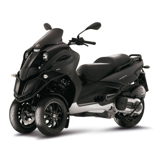
Fuoco 500ie
Ed. 2
Advertisement
Table of Contents

Related Manuals for Gilera Fuoco 500ie


Summary of Contents for Gilera Fuoco 500ie
- Page 1 GILERA WOULD LIKE TO THANK YOU for choosing one of its products. We have prepared this manual to help you to get the very best from your scooter. Please read it carefully before riding the scooter for the first time. It contains information, tips and precautions for using your scooter. It also describes features, details and devices to assure you that you have made the right choice.
- Page 2 The instructions given in this manual are intended to provide a clear, simple guide to using your scooter; this booklet also details routine maintenance procedures and regular checks that should be carried out on the vehicle at an authorised Dealer or Service Centre. The booklet also contains instructions for simple repairs.
- Page 3 Personal safety Failure to completely observe these instructions will result in serious risk of personal injury. Safeguarding the environment Sections marked with this symbol indicate the correct use of the vehicle to prevent dam- aging the environment. Vehicle intactness The incomplete or non-observance of these regulations leads to the risk of serious damage to the vehicle and sometimes even the invalidity of the guarantee.
-
Page 5: Table Of Contents
INDEX VEHICLE..................Checks..................28 Dashboard................Refuelling.................. 28 Analogue instrument panel............11 Tyre pressure................30 Clock..................12 Shock absorbers adjustment............ 31 Digital lcd display..............12 Running in................. 32 Maintenance icons..............13 Starting up the engine............... 33 *MODE* button..............13 Precautions................35 Key switch................. - Page 6 Headlight adjustment............. 64 Front direction indicators............67 Rear optical unit................ 68 Rear turn indicators..............68 Number plate light..............69 Helmet compartment lighting bulb..........69 Rear-view mirrors..............69 Front and rear disc brake............70 Puncture..................71 Periods of inactivity..............71 Cleaning the vehicle..............72 TECHNICAL DATA..............
-
Page 7: Vehicle
Fuoco 500ie Chap. 01 Vehicle... - Page 8 01_01...
-
Page 9: Dashboard
Dashboard (01_01) A = Ignition key-switch B = Hand brake C = Bag hook D = HAZARD button E= Horn button F = Turn indicator switch G = Rear brake lever H = Light switch + PASSING I = Analogue instrument panel L = Digital instrument panel M = Warning light unit N = RUN/OFF switch... - Page 10 01_02...
-
Page 11: Analogue Instrument Panel
Analogue instrument panel (01_02) A = Immobilizer / antitheft LED B= Speedometer with twin scale (Km/h and Mph) C = CLOCK switch D = Digital display E = Front suspension locking system warning light F= SET switch G = Rpm indicator H = Fuel gauge I = Warning light for helmet compartment courtesy light on L = Engine control telltale light and injection system failure warning light... -
Page 12: Clock
Clock (01_03) Pushing the «CLOCK» button for less than 1 second displays the following sequence: • TIME • DATE To set the clock push and hold the «CLOCK» button longer than 3 seconds. The numbers showing the hours will begin flashing. Set the hour using the «SET»... -
Page 13: Maintenance Icons
G = Low fuel warning light H = Trip odometer gauge (B) I = Trip odometer gauge (A) L = Kilometre - mile indicator M = «SET» button N = «CLOCK» button Maintenance icons 01_05 The icons signal the user that scheduled maintenance operations should be carried out. -
Page 14: Key Switch
"Kmi" represents the combination of "km" (kilometres) and "mi" (miles) "°E" represents the combination of "°C" (degrees Celsius) and "°F" (degrees Fahren- heit). By pushing the "MODE" «S» button for less than a second, the icons "km" and "mi" are selected sequentially. Push the "SET"... -
Page 15: Releasing The Steering Wheel
CAUTION DO NOT TURN THE KEY TO «LOCK» OR «OFF» WHILE RIDING. Releasing the steering wheel Reinsert the key «B» and turn it to «KEY OFF». CAUTION DO NOT TURN THE KEY TO «LOCK» OR «OFF» WHILE RIDING. Switch direction indicators (01_09) Lever «F»... -
Page 16: Horn Button
Horn button (01_10) Push the button «E» to sound the horn. 01_10 Light switch (01_11) When the light switch «H» is set to «0», the low-beam light is on. When set to «1», the high-beam light is activated. If the light switch «H» is pressed when set to «2», the high-beam light is activated. -
Page 17: Start-Up Button
Start-up button (01_13) To start the engine, press the starter button «R» after pulling one of the two brake levers. If the rider is not on the vehicle, the suspension lock will start the engine at idling speed. 01_13 Engine stop button (01_14) The engine can be started when the emergency cut-off switch «N»... -
Page 18: The Immobilizer System
The immobilizer system In order to enhance theft protection, the scooter is equipped with a «PIAGGIO IM- MOBILIZER » electronic engine locking device that is activated automatically when the starter key is removed. Upon start-up, the «PIAGGIO IMMOBILIZER» system checks the starter key, and only if this key is recognised will the immobilizer system allow the scooter to be started. -
Page 19: Immobilizerdevice Enabled Indicator Led
WARNING KEEP THE "CODE CARD" AND THE RED HANDGRIP KEY IN A SAFE PLACE (NOT ON YOUR VEHICLE). Immobilizerdevice enabled indicator led (01_19) Activation of the "PIAGGIO IMMOBILIZER" system is signalled by a flashing «A» 01_19 indicator. In order to reduce battery discharge, the indicator LED turns off automatically after 48 hours of uninterrupted functioning. -
Page 20: Programming The Immobilizer System
WARNING EACH KEY HAS ITS OWN AND UNIQUE CODE, WHICH MUST BE STORED BY THE SYSTEM CONTROL UNIT. VIOLENT SHOCKS MAY AFFECT THE ELECTRONIC COMPONENTS OF THE KEY. IF THE VEHICLE IS SOLD, THE MASTER-HANDGRIP KEY (AS WELL AS THE OTHER STARTER KEYS) AND THE "CODE CARD"... -
Page 21: Saddle Opening Remote Control
traction of the previous key). Leave it in this position for 1 to 3 seconds and return it to the «OFF» position. CORRECT PROGRAMMING CHECK PHASE Insert the «MASTER» key, disabling the transponder (i.e., by tilting the key cap by 90°), and turn the key to «ON»... -
Page 22: Remote Control Programming
Remote control programming Follow these steps to program the remote controls: 1. Insert the remote control key to be programmed in the steering lock key block. 2. Turn the key to «ON», press the button on the remote control, release the button, turn the key back to «OFF»... -
Page 23: Accessing The Fuel Tank
WARNING TO AVOID BATTERY DISCHARGE, THE SADDLE OPENING REMOTE CONTROL RADIO RECEIVER DEACTIVATES 7 DAYS AFTER THE LAST TIME THE VEHICLE WAS SHUT OFF. JUST TURN THE KEY TO «ON» TO REACTIVATE THE RECEIVER. Accessing the fuel tank (01_21, 01_22) To open the fuel tank cover, set the key to «OFF»... -
Page 24: Power Supply Socket
Power supply socket (01_23) There is a plug socket "D" inside the helmet compartment. The plug socket may be used for external consumers (mobile phone, inspection light, etc.). CAUTION 01_23 PROLONGED USE OF THE PLUG SOCKET MAY RESULT IN PARTIAL DIS- CHARGE OF THE BATTERY Electric characteristic Plug socket... -
Page 25: Opening The Saddle
WARNING OBJECTS INAPPROPRIATELY ARRANGED INSIDE THE HELMET COMPART- MENT MAY DEFORM THE SADDLE CAUSING THE COURTESY LIGHT TO RE- MAIN ON AND THIS WILL DISCHARGE THE BATTERY. IN ANY CASE, THE WARNING LIGHT "I" ON THE INSTRUMENT PANEL SIGNALS IF THE LIGHT IS ON OR OFF. -
Page 26: Identification
Identification (01_28, 01_29) Identification registration numbers are made up of a prefix and a number stamped on the chassis and on the engine. These numbers must always be quoted when ordering spare parts. We recommend checking that the chassis registration number stamped on the vehicle corresponds with that on the vehicle documentation. -
Page 27: Use
Fuoco 500ie Chap. 02... -
Page 28: Checks
Checks Before using the vehicle, check: 1. There is enough fuel in the fuel tank. 2. The correct fluid level for front and rear brakes. 3. That tyres are properly inflated. 4. The correct functioning of tail lights, headlamp, turn indicators, stop light and license plate light. - Page 29 CAUTION PETROL DAMAGES THE PLASTIC PARTS OF THE BODYWORK. WARNING 02_02 DO NOT RIDE WITH THE FUEL TANK ALMOST EMPTY, LACK OF FUEL CAN DAMAGE THE CATALYTIC CONVERTER. CAUTION USING NON-RECOMMENDED PETROL REDUCES THE EFFICIENCY OF THE EXHAUST AND FUEL SUPPLY SYSTEMS. CAUTION DO NOT USE THE VEHICLE TO THE COMPLETE EXHAUSTION OF THE FUEL;...
-
Page 30: Tyre Pressure
CAUTION USING OILS OTHER THAN THOSE RECOMMENDED CAN SHORTEN THE LIFE OF THE ENGINE. Characteristic Fuel tank (reserve) ~ 12 l (~2 l) Tyre pressure (02_03) Check the tyre pressure and wear periodically (roughly every 500 km). Tyres feature wear indicators; replace tyres as soon as these indicators become visible on the tyre tread. -
Page 31: Shock Absorbers Adjustment
Rear tyre Tubeless 140/70 - 14" 68S or 68P reinf TYRE INFLATION PRESSURE Front tyre pressure (with 1.6 bar (1.8 bar) passenger) Rear tyre pressure (with 2.4 bar (2.6 bar) passenger) Shock absorbers adjustment (02_04, 02_05) The preloading of the springs can be adjusted to 4 positions using the ring nut located in the lower part of the shock absorbers and the specific spanner supplied. -
Page 32: Running In
WARNING WE RECOMMEND WEARING GLOVES WHILE CARRYING OUT THIS OPERA- TION IN ORDER TO AVOID INJURIES. WARNING WE STRONGLY RECOMMEND NOT TO ADJUST BOTH SHOCK ABSORBERS WITH DIFFERENT PRELOADING Running in DURING THE FIRST 1000 KM DO NOT RIDE THE VEHICLE OVER 80% OF ITS MAX. -
Page 33: Starting Up The Engine
Starting up the engine (02_06, 02_07, 02_08) The vehicle is supplied with an ignition cut-off system, activated by the emergency cut-off switch. The engine cannot be started if the ignition cut-off switch is in the OFF position A running engine automatically switches off when the ignition cut-off switch is set to OFF. - Page 34 CAUTION DO NOT START-UP THE ENGINE IN CLOSED AREAS BECAUSE EXHAUST GASES ARE TOXIC. CAUTION DUE TO THE HIGH TEMPERATURES THE CATALYTIC CONVERTER CAN REACH, ALWAYS TAKE CARE, WHEN PARKING THE SCOOTER, THAT THE EXHAUST DOES NOT COME INTO CONTACT WITH FLAMMABLE MATERIALS, TO AVOID SERIOUS BURNS.
-
Page 35: Precautions
WARNING NEVER TRY TO START-UP THE ENGINE WITH THE THROTTLE GRIP TWISTED. THIS MAY LEAD TO LOSING CONTROL OF THE VEHICLE AND TO ROLLOVER, WITH CONSEQUENT SERIOUS OR, IN SOME CASES, LETHAL INJURIES. Precautions CAUTION NEVER STRESS THE ENGINE AT LOW TEMPERATURES IN ORDER TO AVOID POSSIBLE DAMAGE. -
Page 36: Stopping The Engine
Stopping the engine (02_09) Fully untwist the throttle grip, then rotate the key in the switch «A » to «KEY OFF» (extractable key). CAUTION DUE TO THE HIGH TEMPERATURES THE CATALYTIC CONVERTER CAN REACH, ALWAYS TAKE CARE, WHEN PARKING THE SCOOTER, THAT THE 02_09 EXHAUST DOES NOT COME INTO CONTACT WITH FLAMMABLE MATERIALS, TO AVOID SERIOUS BURNS. -
Page 37: Stand
Stand (02_11) Push with your foot on the centre stand's fork "F" while lifting the vehicle backward, holding onto the handlebar. 02_11 Automatic transmission To ensure simple, pleasurable riding, the vehicle is equipped with automatic trans- mission with regulator and centrifugal clutch. The system is designed to provide the best performance (acceleration and consumption) while riding on both flat roads and uphill. - Page 38 of safe riding. We recommend practising riding in traffic-free zones, in order to acquire a good knowledge of your vehicle. 1. Before riding off, remember to put on your helmet and fasten it correctly. 2.Reduce speed on rough roads and drive with care. 3.
- Page 39 WARNING NEVER RIDE THE VEHICLE WITH ADDED ACCESSORIES (CASE AND/OR WINDSHIELD) FASTER THAN 120 KM/H. WITHOUT THESE ACCESSORIES THE VEHICLE MAY BE DRIVEN AT A HIGHER SPEED WITHIN THE LEGAL LIMITS. IF THERE ARE NOT-PIAGGO ACCESSORIES FITTED, OR AN ABNORMAL LOAD, OR IF THE VEHICLE IS NOT IN A GENERALLY GOOD CONDITION, OR WHEN- EVER WEATHER CONDITIONS DEMAND IT, SPEED SHOULD BE FURTHER REDUCED.
-
Page 40: Front Suspension Locking System
Front suspension locking system (02_12, 02_13, 02_14, 02_15, 02_16, 02_17) The front suspension locking system simply prevents vehicle tilting when the «Q» switch is pressed. The warning light «E» starts flashing when the key switch is set to «ON». This means that the system is enabled for locking activation. - Page 41 CAUTION THE RIDER DETECTION SENSOR IS LOCATED IN THE FRONT PART OF THE SADDLE. AVOID PLACING BAGS OR HEAVY OBJECTS ACCIDENTALLY ON THE SADDLE. NOT OBSERVING THIS RULE MAY MOVE THE VEHICLE FORWARD AND RE- LEASE THE SUSPENSION LOCKING SYSTEM EVEN IF THE RIDER IS NOT SEATED, BY SIMPLY TWISTING THE THROTTLE.
- Page 42 WARNING IF THE RIDER IS NOT SEATED ON THE SADDLE WHILE THE VEHICLE IS IN MOTION AND THE LOCKING SYSTEM IS ENGAGED, AVOID OPERATING THE THROTTLE CONTROL PURPOSELESSLY AS THIS MAY DAMAGE THE CATA- LYTIC CONVERTER. CAUTION DO NOT RIDE DOWNHILL WITH THE SUSPENSION LOCKING SYSTEM ENGAG- ED AND THE KEY SWITCH SET TO OFF.
- Page 43 THAT THE POTENTIAL MOVEMENT CAUSED BY THE SLOPE TAKES THAT WHEEL AGAINST THE SIDEWALK. WITH THE STEERING LOCK ENGAGED, MANOEUVRE SO THAT THE SIDEWALK IS TO THE RIGHT WHEN YOUR VEHI- CLE IS PARKED UPHILL AND TO THE LEFT WHEN PARKED DOWNHILL. If the WARNING light «C»...
-
Page 45: Maintenance
Fuoco 500ie Chap. 03 Maintenance... -
Page 46: Engine Oil Level
Engine oil level In 4T engines, engine oil is used to lubricate the distribution elements, main bearings and thermal group. An insufficient quantity of oil can cause serious damage to the engine itself. In all four-stroke engines, a loss of efficiency in oil performance and consumption should be considered normal. -
Page 47: Engine Oil Change
necessary to check the oil level and top it up if required. If after having topped- up the oil, the warning light still comes on while braking, at idle speed or while turning a corner, it will be necessary to take your vehicle to an Authorised Serv- ice Centre. -
Page 48: Hub Oil Level
Recommended products AGIP CITY HI TEC 4T Engine oil SAE 5W-40, API SL, ACEA A3, JASO MA Synthetic oil Hub oil level (03_05, 03_06) Check the oil in the rear hub. (oil content ~ 250 cc). To check the rear hub oil level, proceed as follows: 1) Rest the vehicle onto its centre stand, on level ground. - Page 49 CAUTION AN EXCESSIVE QUANTITY OF OIL CAN LEAD TO LEAKAGE, WHICH MAY CAUSE THE ENGINE AND THE WHEEL TO GET DIRTY. CAUTION WHEN REPLACING THE HUB OIL DO NOT LET THE OIL COME INTO CONTACT WITH THE REAR BRAKE DISC. CAUTION FOR OIL REPLACEMENT, CONTACT ANY AUTHORISED SERVICE CENTRE AS THEY ARE EQUIPPED TO DISPOSE OF USED OILS IN AN ENVIRONMENTALLY...
-
Page 50: Tyres
Tyres (03_07) Check the tyre pressure and wear periodically (roughly every 500 km). Tyres feature wear indicators; replace tyres as soon as these indicators become visible on the tyre tread. Also check that the tyres do not show signs of splitting at the side or irregular tread wear;... -
Page 51: Spark Plug Dismantlement
TYRE INFLATION PRESSURE Front tyre pressure (with 1.6 bar (1.8 bar) passenger) Rear tyre pressure (with 2.4 bar (2.6 bar) passenger) Spark plug dismantlement (03_08, 03_09) This engine has two spark plugs. Remove the port on the left-hand side panel of the vehicle by undoing the fixing screw «A»... -
Page 52: Removing The Air Filter
N.B. THE USE OF SPARK PLUGS OTHER THAN THE INDICATED TYPE OR OF SHIELDLESS SPARK PLUG CAPS CAN CAUSE ELECTRICAL SYSTEM FAIL- URES. Characteristic Spark plug NGK CR7EKB Electrode gap 0.7 ÷ 0.9 mm Removing the air filter (03_10) Proceed as follows: Unscrew the nine fixing screws «A»... -
Page 53: Cooling Fluid Level
CAUTION IF THE VEHICLE IS USED ON DUSTY ROADS IT IS NECESSARY TO CARRY OUT MAINTENANCE CONTROLS OF THE AIR FILTER TO AVOID DAMAGING THE ENGINE. Recommended products AGIP FILTER OIL Oil for air filter sponge Mineral oil with specific additives for increased adhesiveness Cooling fluid level (03_11, 03_12, 03_13, 03_14) The engine cooling system operates by forcing circulation of fluid. - Page 54 If it is necessary to top up the coolant frequently, or if the expansion tank is completely dry, you should look for the cause in the cooling system. It is therefore essential to have the cooling system checked at an Authorised Service Centre. Replace coolant as indicated in the scheduled maintenance table.
-
Page 55: Checking The Brake Oil Level
Recommended products SPECIAL AGIP PERMANENT fluid coolant Monoethylene glycol-based antifreeze fluid, CUNA NC 956-16 Checking the brake oil level (03_15) The front and rear brake fluid reservoirs are both positioned on the handlebars. Pro- ceed as follows: 1. Place the scooter on its centre stand and make sure the handlebar is centred; 2. - Page 56 WARNING ONLY USE DOT 4 CLASS BRAKE FLUIDS. COOLING SYSTEM FLUIDS ARE HIGHLY CORROSIVE. MAKE SURE THAT IT DOES NOT COME INTO CONTACT WITH THE PAINTWORK CAUTION AVOID CONTACT OF BRAKE FLUID WITH EYES, SKIN, AND CLOTHING. IN CASE OF CONTACT, RINSE WITH WATER. THE BRAKING CIRCUIT FLUID IS HYGROSCOPIC, THAT IS, IT ABSORBS HUMIDITY FROM THE SURROUNDING AIR.
-
Page 57: Battery
Battery (03_17) To access the battery, proceed as follows: 1. Place the scooter on its centre stand; 2. Open the saddle, following the previously described procedure; 3. Remove the two fasteners "A" and the cover "B". WARNING 03_17 IN ORDER TO AVOID DAMAGING THE ELECTRICAL SYSTEM, NEVER DISCON- NECT THE WIRING WHILE THE ENGINE IS RUNNING. -
Page 58: Long Periods Of Inactivity
Long periods of inactivity If the vehicle has not been used for long periods, it is necessary to periodically re- charge the battery, bearing in mind that the battery tends to go completely flat within around three months. The battery must be recharged with a current load equal to 1/10 of the battery rated capacity (~ 1A ), for a period not longer than 8 hours. - Page 59 03_21 03_22 03_23...
- Page 60 FUSE TABLE Fuse No. 1 Capacity: 7.5 A Protected circuits:Injection ECU battery power Fuse No. 2 Capacity: 15 A Protected circuits:Battery- powered injection loads, electrical Fuse No. 3 Capacity: 15 A Protected circuits:Battery- powered saddle opening switch, glove-box lighting, light switch, turn indicator switch, antitheft...
- Page 61 Protected circuits:Battery- powered instrument panel Fuse No. 8 Capacity: 10A Protected circuits:Live stop, start-up and start-up enabling switch and start-up circuit. Fuse No. 9 Capacity: 7.5 A Protected circuits:live passing and horn Fuse No. 10 Capacity: 7.5A Protected circuits:Live injection ECU, immobilizer aerial, electric fan remote control, injection loads remote control...
- Page 62 IGHT BULBS TABLE Low-beam bulb Type: HALOGEN (H8) Power: 12V - 35W Quantity: 1 RHS + 1 LHS High-beam light bulb Type: HALOGEN (H8) Power: 12V - 35W Quantity: 1 RHS + 1 LHS Helmet compartment light bulb Type: FESTOON BULB Power: 12V - 5W Quantity: 1 Rear turn indicator light bulb...
-
Page 63: Front Light Group
Front light group (03_24, 03_25, 03_26, 03_27, 03_28, 03_29) To access the tail light bulb: - Insert a screwdriver in the notch on the side (see picture) of the Gilera emblem and remove it. - Undo the screw «A» and the four screws «B». -
Page 64: Headlight Adjustment
To replace it, disconnect the connector and insert a new bulb WARNING HIGH AND LOW BEAM LIGHT ARE OF THE HALOGEN TYPE: DO NOT TOUCH WITH YOUR FINGERS TO AVOID DAMAGING THEIR FUNCTION. Headlight adjustment (03_30, 03_31, 03_32, 03_33, 03_34) 03_25 Proceed as follows: - Position the unloaded vehicle, in running order and with the tyres inflated to the... - Page 65 do that, remove the connector from the other bulbs so that you can adjust one head- lamp at a time. N.B. THE HEADLAMPS CAN ONLY BE LIT WHEN THE ENGINE IS ON. ADJUST THE LIGHT BEAM IN A WELL VENTILATED PLACE. 03_28 03_29 03_30...
- Page 66 03_31 03_32 03_33...
-
Page 67: Front Direction Indicators
03_34 Front direction indicators (03_35) To access the bulb, undo the screw «A» and remove the glass «B». To replace the bulb, hold it and then turn it clockwise. 03_35... -
Page 68: Rear Optical Unit
Rear optical unit (03_36, 03_37) To access the rear light unit bulbs, undo the screw «A» and remove the glass «B». Now tighten the screw «A» in its seat. To replace the stop light bulb «C», hold it and turn it anticlockwise. To replace the rear tail light bulb «D», hold it and pull it outwards. -
Page 69: Number Plate Light
Number plate light (03_39) Remove the screw «C», then take out the bulb holder. 03_39 Helmet compartment lighting bulb (03_40) Open the rear boot and insert a small plain slot screwdriver in the lateral notch to detach the snap-on glass "D", then replace the bulb. 03_40 Rear-view mirrors (03_41) The mirrors can be set to the desired position by adjusting the mirror frame. -
Page 70: Front And Rear Disc Brake
Front and rear disc brake The brake disc and pad wear is automatically compensated, therefore it has no effect on the functioning of the front and rear brakes. For this reason it is not necessary to adjust the brakes. An excessively elastic brake lever stroke may indicate the presence of air in the braking circuit or a failure in the braking system. -
Page 71: Puncture
ORDER TO AVOID THIS, WE RECOMMEND WASHING THE VEHICLE FRE- QUENTLY WHEN RIDING IN THESE ROAD CONDITIONS. Puncture The vehicle is equipped with tubeless tyres (without inner tube). In the event of a puncture, contrary to the situation with a tyre with inner tube, the tyre deflates more slowly, resulting in a greater steering safety. -
Page 72: Cleaning The Vehicle
2. Be careful to rest the vehicle on its centre stand disabling the front suspension locking system; 3. With engine off and piston at the bottom dead centre, remove the spark plug, add 1÷2 cc of oil through the opening (adding more oil may damage the engine). Operate the starter button 1-2 times for roughly 1 second to turn the engine over slowly, then insert the spark plug again;... - Page 73 CAUTION PER IL LAVAGGIO DEL MOTORE E DEL VEICOLO É SCONSIGLIATO L'UTILIZ- ZO DELL'IDROPULITRICE; NEL CASO CHE NON SIA POSSIBILE EFFETTUARE TALE OPERAZIONE IN UN ALTRO MODO, É NECESSARIO: • USARE SOLAMENTE IL GETTO A VENTAGLIO. • NON AVVICINARE LA LANCIA A MENO DI 2 FT (60 CM). •...
- Page 74 STARTING FAILURE Emergency switch in «OFF» Set the switch back to «ON» Fuse blown Replace the blown fuse and have the vehicle checked by an Authorised Service Centre. IGNITION PROBLEM Faulty spark plug Contact an Authorised Service Centre. Faulty ignition / injection control Contact an Authorised Service unit.
- Page 75 HIGH CONSUMPTION AND LOW PERFORMANCE Air filter blocked or dirty. Clean with water and shampoo and impregnate with petrol and specific oil (section «Removing the air filter») INSUFFICIENT BRAKING Greasy disc. Worn pads. Faulty Contact an Authorised Service braking system. Presence of air in Centre.
-
Page 77: Technical Data
Fuoco 500ie Chap. 04 Technical data... - Page 78 04_01...
- Page 79 ENGINE TECHNICAL DATA Type Single-cylinder, 4-stroke Cubic capacity 493 cm³ Bore x Stroke 94 x 71 mm Compression ratio 10.5 ± 0.5 : 1 Engine idle speed 1,500 ± 100 rpm Timing system Four valves, single overhead camshaft, chain driven. Valve clearance Inlet: 0.15 mm Outlet: 0.15 mm...
- Page 80 Ignition Highly efficient electronic inductive ignition, integrated with the injection system, with variable advance, separate HV coil and double spark plug. Ignition advance Three-dimensional map managed by control unit Spark plug NGK CR7EKB Alternative spark plug Fuel supply Electronic injection with electric fuel pump.
- Page 81 Front brake Ø 240 mm double disk with hydraulic control activated by the handlebar right-hand lever. Rear brake disc brake, diameter 240 mm, with hydraulic servo operated from the handlebar with the left-hand lever. Wheel rim type Light alloy rims. Front rim 12'' x 3.00 Rear rim...
-
Page 82: Kit Equipment
Kit equipment (04_02) The toolkit comprises: - One box-spanner. - One twin screwdriver - One special spanner for adjusting the rear shock absorbers - One plastic clip for removing the fuses. The tools are stored in the helmet compartment. 04_02... -
Page 83: Spare Parts And Accessories
Fuoco 500ie Chap. 05 Spare parts and accessories... -
Page 84: Warnings
Warnings (05_01) WARNING TO PREVENT ACCIDENTS AND TO GUARANTEE PROPER STABILITY, PER- FORMANCE AND SAFETY, RIDE THE VEHICLE VERY CAREFULLY WHEN IT IS FITTED WITH ACCESSORIES OR WITH UNUSUAL LOADS. WARNING 05_01 IT IS ALSO RECOMMENDED THAT "ORIGINAL PIAGGIO SPARE PARTS" BE USED, AS THESE ARE THE ONLY ONES OFFERING YOU THE SAME QUALITY GUARANTEE AS THOSE INITIALLY FITTED ON THE SCOOTER. - Page 85 THERE ARE NOT-PIAGGO ACCESSORIES FITTED, OR AN ABNORMAL LOAD, OR IF THE VEHICLE IS NOT IN A GENERALLY GOOD CONDITION, OR WHEN- EVER WEATHER CONDITIONS DEMAND IT, SPEED SHOULD BE FURTHER REDUCED. WARNING BE EXTREMELY CAREFUL WHEN INSTALLING AND REMOVING THE MECHAN- ICAL ANTITHEFT DEVICE ON THE VEHICLE (U-SHAPED PADLOCK, DISC BLOCK, ETC.).
-
Page 87: Programmed Maintenance
Fuoco 500ie Chap. 06 Programmed maintenance... -
Page 88: Scheduled Maintenance Table
Scheduled maintenance table Adequate maintenance is fundamental to ensuring long-lasting, optimum operation and performance of your vehicle. To this end, a series of checks and maintenance operations (at the owner's expense) have been suggested, which are included in the summary table on the following page. Any minor faults should be reported without delay to an Authorised Service Centre or Dealer without waiting until the next scheduled service to solve it. - Page 89 Engine oil - replacement Brake pads - check condition and wear Tyre pressure and wear - check Vehicle and brake test - road test Hub oil - change Steering - Check Parking control unit software upgrading (if available) AFTER 5,000 KM; 25,000 KM; 35,000 KM; 55,000 KM; 65,000 KM Engine oil - level check/ top-up Brake pads - check condition and wear...
- Page 90 Coolant level - check Brake fluid level - check Engine oil - replacement Brake pads - check condition and wear Sliding block / variable speed rollers - change Tyre pressure and wear - check Vehicle and brake test - road test Hub oil - check Suspensions - check Steering - Check...
- Page 91 AFTER 20,000 KM; 40,000 KM; 60,000 KM AND 80,000 Spark plugs - replacement Driving belt - replacement Throttle lever - adjustment Air filter - check Engine oil - change Valve clearance - check Electrical system and battery - check Coolant level - check Engine oil - replacement Brake pads - check condition and wear Sliding block / variable speed rollers - change...
- Page 92 30,000 KM Safety locks - check Driving Belt - replacement Throttle lever - adjustment Air filter - clean Engine oil - change Electrical system and battery - check Coolant level - check Brake fluid level - check Engine oil - replacement Hub oil - check Brake pads - check condition and wear Sliding block / variable speed rollers - change...
- Page 93 RECOMMENDED PRODUCTS TABLE Product Description Specifications AGIP ROTRA 80W-90 Rear hub oil SAE 80W/90 Oil that exceeds the requirements of API GL3 specifications AGIP GP 330 Grease for brake control levers, throttle, stand White calcium complex soap-based spray grease with NLGI 2; ISO-L-XBCIB2 AGIP CITY HI TEC 4T Oil to lubricate flexible transmissions (throttle Oil for 4-stroke engines...
- Page 95 TABLE OF CONTENTS Tyre pressure: 30 Tyres: 50 Air filter: 52 Fuel: 23 Light switch: 16 Fuses: 58 Battery: 57 Maintenance: 13, 45, 87, 88 Brake: 55, 70 Headlight: 64 Mirrors: 69 Horn: 16 Hub oil: 48 Clock: 12 Saddle: 21, 24, 25 Scheduled maintenance: 88 Identification: 26 Shock absorbers: 31...
- Page 96 The descriptions and illustrations given in this publication are not binding. While the basic features as described and illustrated in this manual remain unchanged, PIAGGIO - GILERA reserves the right, at any time and without being required to update this publication beforehand, to make any changes to components, parts or accessory supplies, which it considers necessary to improve the product or which are required for manufacturing or construction reasons.
Need help?
Do you have a question about the Fuoco 500ie and is the answer not in the manual?
Questions and answers