Sign In
Upload
Download
Table of Contents
Contents
Add to my manuals
Delete from my manuals
Share
URL of this page:
HTML Link:
Bookmark this page
Add
Manual will be automatically added to "My Manuals"
Print this page
×
Bookmark added
×
Added to my manuals
Manuals
Brands
Husqvarna Manuals
Motorcycle
2013 CR 125
Owner's manual
Husqvarna 2013 CR 125 Owner's Manual
Hide thumbs
1
2
3
4
5
6
7
8
9
10
11
12
13
14
15
16
17
18
19
20
21
22
23
24
25
26
27
28
29
30
31
32
33
34
35
36
37
38
39
40
41
42
43
44
45
46
47
48
49
Table Of Contents
50
page
of
50
Go
/
50
Contents
Table of Contents
Bookmarks
Table of Contents
Table of Contents
Presentation
Motocross
Enduro
Important Notices
Important Notice
Precautions for Children
Vehicle Identification Number (V.I.n.)
Identification Data
Cr - Wr Usa Control Location
Wr Control Location
Technical Data
Table for Lubrication, Supplies
Dimension, Weight, Capacity
Lubrication Table, Supplies
Sidestand
CR - WR USA Fuel Cock
WR Fuel Cock
Controls
Fuel
Carburetor Choke
Digital Instrument, Warning Lights (Wr)
Speed
Speed / Chrono (Stp)
Speed / Trip 1
Speed / Clock
Throttle Control
Steering Lock (Wr)
Handlebar Commutator (Wr)
Engine Stop Button (Cr - Wr Usa)
Clutch Control
Rear Brake Control
Gear Shift Control
Kickstart Pedal
Checks While Running in
Running in
Riding
Engine Start
Stopping the Motorcycle and the Engine
Transmission Oil Level Checking
Changing Transmission/Gearbox Oil
Coolant Level Check
Coolant Replacement
Throttle Cable Adjustment
Idle Adjustment
Adjustment of the Clutch Control Lever
Spark Control
Correct Heat Rating
Assembly
Air Filter and Cleaning
Air Filter Check
Steering Wheel Ball Play Adjustment
Adjustment of the Control Lever
Check of the Front Brake Fluid Level
Rear Brake Pedal Position Adjustment
Rear Brake Idle Stroke Adjustment
Checking the Fluid Level
Adjusting the Suspensions According to Particular Track Conditions
Hard Ground
Sandy Ground
Muddy Ground
Oil Quantity in each Fork Leg
Oil Fork Level
Adjusting the Compression Fork
Adjusting the Shock Absorber
Shock Absorber Spring Preload Adjustment
Shock Absorber Damping Adjustment
Chain Adjustment
Quick Adjustment
Checking the Wear of Chain, Pinion and Sprocket
Lubricating the Chain
Disassembling and Cleaning
Lubricating the Chain Without or (CR)
Lubricating the Chain with or (WR)
Removing the Front Wheel
Reassembling the Front Wheel
Removing the Rear Wheel
Tires
Brakes
Brake Pads Removal
Pads Wear
Pads Cleaning
Pads Installation
Brake Disc Wear
Disc Warpage
Disc Cleaning
Electrical Components Location
Ignition System/Elettrical System
Headlamp Bulbs Replacement (Wr)
Tail Light (Wr)
Replacing the Number Plate Lamp (Wr)
Adjustment of Headlight (Wr)
After-Race Check Points
Storage
Warning
Appendix
Cleaning
Important Recommendation
After Washing
Pre -Delivery Inspection
Alphabetic Index
Advertisement
Quick Links
1
Table of Contents
2
Technical Data
3
Lubrication Table, Supplies
4
Table for Lubrication, Supplies
5
Ignition System/Elettrical System
Download this manual
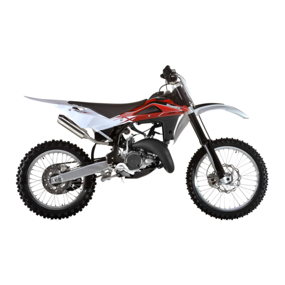
CR 125 - CR 125 USA 2013
WR 125 - WR 125 USA 2013
Manuale utente_Owner's manual_Manuel d'utilisateur_Benutzerhandbuch_Manual del usuario
Table of
Contents
Previous
Page
Next
Page
1
2
3
4
5
Advertisement
Table of Contents
Need help?
Do you have a question about the 2013 CR 125 and is the answer not in the manual?
Ask a question
Questions and answers
Related Manuals for Husqvarna 2013 CR 125
Motorcycle Husqvarna CR125/2007 Workshop Manual
(419 pages)
Motorcycle Husqvarna WR 250/2004 Owner's Manual
(306 pages)
Motorcycle Husqvarna WR 250/2004 Workshop Manual
(364 pages)
Motorcycle Husqvarna 2004 CR 250 Workshop Manual
Husqvarna 2004 wr 250/cr 250 motorcycle (364 pages)
Motorcycle Husqvarna 250 CR Owner's Manual
(66 pages)
Motorcycle Husqvarna 240 CR Engine Shop Manual
(34 pages)
Motorcycle Husqvarna 2004 WR 250 Owner's Manual
(306 pages)
Motorcycle Husqvarna 2004 WR 125 Owner's Manual
(308 pages)
Motorcycle Husqvarna CR 125 2009 Owner's Manual
(258 pages)
Motorcycle Husqvarna CR 125 2010 Manual
Specifications - operation - maintenance (344 pages)
Motorcycle Husqvarna CP Owner's Manual
(87 pages)
Motorcycle Husqvarna CR 125/2002 Owner's Manual
(280 pages)
Motorcycle Husqvarna CR 250/2003 Workshop Manual
(46 pages)
Motorcycle Husqvarna CR 65 2012 Workshop Manual
(174 pages)
Motorcycle Husqvarna CR 125 2011 Specifications - Operation - Maintenance
(290 pages)
Motorcycle Husqvarna 2004 WR 125 Owner's Manual
(305 pages)
This manual is also suitable for:
2013 wr 125
Table of Contents
Save PDF
Print
Rename the bookmark
Delete bookmark?
Delete from my manuals?
Login
Sign In
OR
Sign in with Facebook
Sign in with Google
Upload manual
Upload from disk
Upload from URL


Need help?
Do you have a question about the 2013 CR 125 and is the answer not in the manual?
Questions and answers