Advertisement
Quick Links
QQ
3 7 63 1515 0
SERVICE MANUAL
TE
L 13942296513
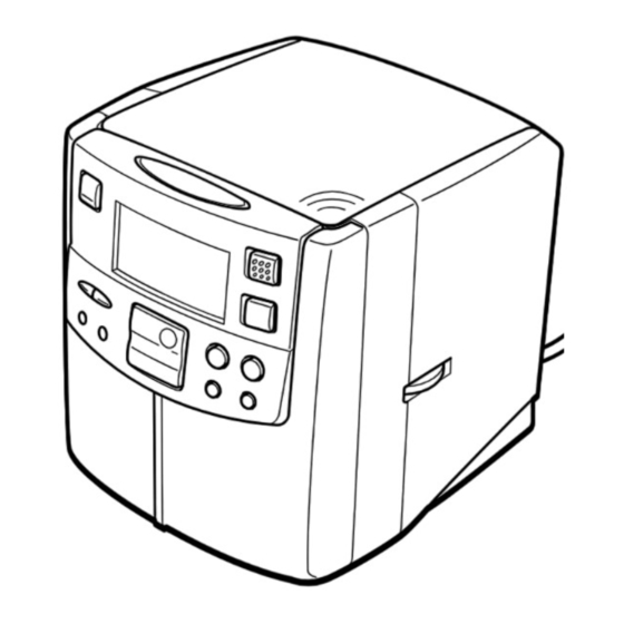
COMPACT DISC STEREO
RADIO RECEIVER
This Service Manual is the "Revision Publishing" and replaces "Simple Manual"
(S/M Code No. 09-015-356-5T1).
www
.
http://www.xiaoyu163.com
x
ao
u163
y
i
S/M Code No. 09-015-356-5R1
http://www.xiaoyu163.com
FR-CD2500
2 9
8
Q Q
3
6 7
1 3
1 5
BASIC CD MECHANISM : DA11T3C
co
.
U(S),EZ(S)
9 4
2 8
0 5
8
2 9
9 4
2 8
m
9 9
9 9
Advertisement

Related Manuals for Aiwa FR-CD2500


Summary of Contents for Aiwa FR-CD2500
- Page 1 FR-CD2500 U(S),EZ(S) 3 7 63 1515 0 SERVICE MANUAL L 13942296513 COMPACT DISC STEREO BASIC CD MECHANISM : DA11T3C RADIO RECEIVER This Service Manual is the "Revision Publishing" and replaces "Simple Manual" (S/M Code No. 09-015-356-5T1). u163 S/M Code No. 09-015-356-5R1...
-
Page 2: Specifications
http://www.xiaoyu163.com SPECIFICATIONS 3 7 63 1515 0 U MODEL <Tuner section> Frequency range FM: 87.5 – 108 MHz (100 kHz steps) AM: 530 – 1,710 kHz (10 kHz steps) Antennas FM wire antenna Ferrite bar antenna for AM <CD player section> Tracking system 3-beam laser Laser pickup... -
Page 3: Protection Of Eyes From Laser Beam During Servicing
http://www.xiaoyu163.com PROTECTION OF EYES FROM LASER BEAM DURING SERVICING 3 7 63 1515 0 This set employs laser. Therefore, be sure to follow carefully the CAUTION instructions below when servicing. Use of controls or adjustments or performance of procedures other than those specified herein may result in hazardous WARNING! radiation exposure. - Page 4 http://www.xiaoyu163.com Precaution to replace Optical block 3 7 63 1515 0 (SF-P101NR) Body or clothes electrostatic potential could ruin laser diode in the optical block. Be sure ground body and workbench, and use care the clothes do not touch the diode. 1) After the connection, remove solder shown in the right figure.
- Page 5 http://www.xiaoyu163.com ELECTRICAL MAIN PARTS LIST-1/3 3 7 63 1515 0 REF. NO PART NO. KANRI DESCRIPTION REF. NO PART NO. KANRI DESCRIPTION C137 87-010-404-080 CAP, ELECT 4.7-50V C138 87-018-112-080 CAP,TC U 30P-50 J SL UP050 8A-RU2-606-010 IC,TC9284BF C139 87-018-112-080 CAP,TC U 30P-50 J SL UP050 8A-RU2-605-010 IC,TA2065F C140...
- Page 6 http://www.xiaoyu163.com ELECTRICAL MAIN PARTS LIST-2/3 3 7 63 1515 0 REF. NO PART NO. KANRI DESCRIPTION REF. NO PART NO. KANRI DESCRIPTION 8A-RU2-662-010 SPKR, F66RZ3201 87-018-119-080 CAP, CER 100P-50V SW417 8B-RD3-639-010 SW,TACT 1120V-4 87-010-263-080 CAP, ELECT 100-10V T103 8A-RU2-607-010 IFT,4A224R 87-018-134-080 CAPACITOR,TC-U 0.01-16 T151...
-
Page 7: Chip Resistor Part Code
http://www.xiaoyu163.com ELECTRICAL MAIN PARTS LIST-3/3 3 7 63 1515 0 REF. NO PART NO. KANRI DESCRIPTION REF. NO PART NO. KANRI DESCRIPTION SW410 8A-RU2-623-010 SW,TACT 5MM POWER C.B SW411 8A-RU2-623-010 SW,TACT 5MM SW412 8A-RU2-623-010 SW,TACT 5MM 8A-RU2-664-010 AC CORD, SPT-2 SW413 8A-RU2-623-010 SW,TACT 5MM... - Page 8 http://www.xiaoyu163.com BLOCK DIAGRAM-1/2 (TUNER / AMP & CPU SECTION) 3 7 6 3 1 5 1 5 0 MAIN C.B FM OSC D103 L103 FM RF Q107 FM-RF-OUT D104 TC102,L102 Q102 LPF2 Q103 18 19 AM/IF RF IF MPX 13 11 10 MW RF LPF1 IC101 TA2104AN...
- Page 9 http://www.xiaoyu163.com BLOCK DIAGRAM-2/2 (CD SECTION) 3 7 6 3 1 5 1 5 0 CD MECHANISM CD C.B DA11T3C +2.5V OPTICAL VREF PICK UP SF-P101NR +IN2 AUDIO RFRP RFRP -IN2 FILTER SBAD SBAD -IN1 TC9284B DMON DMEN TA2065BF +IN1 BA4558 16 24 26 30 14 15 16 17 18 19 SERVO SIGNAL...
- Page 10 http://www.xiaoyu163.com WIRING-1/3 (MAIN, POWER) 3 7 63 1515 0 L151 (MW) L152 (LW) MAIN C.B (INSERTED PARTS) FM ANT SW417 RESET C161 CHIP PARTS SIDE C149 INSERTED PARTS SIDE L 13942296513 HP201 D216 C232 TO CONTROL C.B CON402 POWER C.B (INSERTED PARTS) CON202 2.5 inch 8 Ω...
- Page 11 http://www.xiaoyu163.com SCHEMATIC DIAGRAM-1/3 (MAIN, POWER) 3 7 6 3 1 5 1 5 0 VT ADJUSTMENT : Ref. No. MAIN C.B MW : LOW END IS 0.9V C148 0.01uF 0.02uF LW : LOW END IS 1.0V C157 5600P 0.02uF FM : LOW END IS 2.0V 4.7K L102,TC102 FM TRACKING ADJ.
- Page 12 http://www.xiaoyu163.com WIRING-2/3 (CD, MOTOR) 3 7 63 1515 0 OTOR C.B (CONDUCTOR SIDE) (SLED MOTOR) (INSIDE LIMIT SW) (SPINDLE MOTOR) CD C.B OPTICAL PICK UP (INSERTED PARTS) SF-P101NR LEAF SW L 13942296513 TO CONTROL C.B Note u163 E C B E C B -12- http://www.xiaoyu163.com...
- Page 13 http://www.xiaoyu163.com SCHEMATIC DIAGRAM- 2/3 (CD, MOTOR) 3 7 6 3 1 5 1 5 0 CD C.B AUDIO FILTER LD AMP CD MECHANISM R/W SW R72 3.9K RF ADJ. DA11T3C (1/2) EF BALANCE ADJ. C67 100P CON1 R74 3.9K 2SC1815GR 120K 2.2PF 240K...
- Page 14 http://www.xiaoyu163.com WIRING-3/3 (CONTROL) 3 7 63 1515 0 CONTROL C.B SW413 (INSERTED PARTS) FUNCTION SW416 SW412 SW410 SNOOZE BAND/ POWER STAND BY/ON SUMMER.T/DST R416 R474 R470 DP401 (2/2) C415 R475 R473 R409 R421 R482 R476 R471 C417 R472 R477 IC401 R431 DP401 (1/2) (LCD DISPLAY) R479...
- Page 15 http://www.xiaoyu163.com SCHEMATIC DIAGRAM-3/3 (CONTROL) 3 7 6 3 1 5 1 5 0 CONTROL C.B 1.5K 2.2K 3.3K 5.6K RANDOM/ REPET/ ALARM SKIP DOWN 1.5K 2.2K 3.3K 5.6K 90980TT JW427 220uH 3.3K 1.5K 2.2K 5.6K POWER BAND/ FUNCTION STANDBY/ON SUMMER.T/DST 120/16V 1 3 9 4 2 2 9 6 5 1 3 C445...
- Page 16 http://www.xiaoyu163.com TRANSISTOR ILLUSTRATION-1/1 3 7 63 1515 0 E C B E C B E C B 2SC1815 2SC1740 2SB562B DTC114ESA 2SD1468 DTC114YS DTC114YSA S G D B C E E C B 3CA8550 2SB1566 2SK118 3DA8050 L 13942296513 u163 -16- http://www.xiaoyu163.com...
- Page 17 http://www.xiaoyu163.com IC BLOCK DIAGRAM-1/1 3 7 63 1515 0 IC, BA4558N IC, TA2104AN FM RF OUT RF VCC AM RF IN FM OSC AM OSC OSC OUT ST LED IF REQ DET OUT LPF1 LPF2 L 13942296513 BUFF DECODE DIVIDE BUFF BUFF LEVEL...
- Page 18 http://www.xiaoyu163.com ELECTRICAL ADJUSTMENT-1/3 (TUNER SECTION : U) 3 7 63 1515 0 < TUNER SECTION : U MODEL > MAIN C.B MW COLL L151 TC151 TC102 T103 test point R102 L102 L103 T151 test point L 13942296513 1. AM IF Adjustment 4.
- Page 19 http://www.xiaoyu163.com ELECTRICAL ADJUSTMENT-2/3 (TUNER SECTION : EZ) 3 7 63 1515 0 < TUNER SECTION : EZ MODEL > MAIN C.B LW COLL MW COLL L151 L152 TC151 TC152 TC102 R102 T103 test point L102 L103 T151 T152 test point L 13942296513 1.
- Page 20 http://www.xiaoyu163.com ELECTRICAL ADJUSTMENT-3/3 (CD SECTION) 3 7 63 1515 0 < CD SECTION > CD C.B test point VREF JW35 L 13942296513 1. RF Adjustment 2. EF Balance Adjustment Test point: RF (IC2 1PIN) and VREF (IC2 3PIN) Test point: TSO (IC2 35PIN) and VREF (IC2 3PIN) 1) Connect the oscilloscope to the test points.
- Page 21 http://www.xiaoyu163.com VOLTAGE CHART-1/2 3 7 63 1515 0 THE MEASURED VALUE IS DC VOLTAGE UNIT: V TUNER SECTION TEST CONDITION:SET AM/FM TUNER ON ONE FREQUENCY IC101 (TA2104AN) PIN'S NUMBER 1.15 5.68 5.73 5.05 5.73 0.45 5.15 1.26 1.25 0.78 0.15 4.33 4.57 4.03...
- Page 22 http://www.xiaoyu163.com VOLTAGE CHART-2/2 3 7 63 1515 0 IC1 (TC9284BF) PIN'S NUMBER 2.95 2.81 4.89 2.80 2.56 4.86 4.86 4.87 4.89 4.89 PIN'S NUMBER 4.37 4.28 4.28 4.29 4.22 2.27 4.88 0.08 PIN'S NUMBER 4.89 2.07 2.07 0.28 2.08 1.69 2.07 4.86 1.79...
- Page 23 http://www.xiaoyu163.com FL (90980TT) GRID ASSIGNMENT/ANODE CONNECTION-1/1 3 7 63 1515 0 GRID ASSIGNMENT L 13942296513 ANODE CONNECTION u163 -23- http://www.xiaoyu163.com...
- Page 24 http://www.xiaoyu163.com IC DESCRIPTION-1/4 (TC9256P)-1/1 3 7 63 1515 0 Pin No. Pin Name Description Crystal ocsillator pins. Connect 7.2MHz crystal oscillator to supply reference frequency and internal clock. Crystal ocsillator pins. Connect 7.2MHz crystal oscillator to supply reference frequency and ______ internal clock.
- Page 25 http://www.xiaoyu163.com IC DESCRIPTION-2/4 (TC9284BF)-1/3 3 7 63 1515 0 Pin No. Pin Name Description GNDA — D/A converter R-channel analog GND. R-channel data positive output. ______ R-channel data inverted output. — D/A converter power supply. ______ L-channel data inverted output. L-channel data positive output.
- Page 26 http://www.xiaoyu163.com IC DESCRIPTION-2/4 (TC9284BF)-2/3 3 7 63 1515 0 Pin No. Pin Name Description Disc motor CLV servo AFC signal output. Operation Command DMFC output Motor acceleration DMFK “2VREF” DMFC CLV servo ON DMSV AFC signal (PWM) Motor brake DMBK “L”...
- Page 27 http://www.xiaoyu163.com IC DESCRIPTION-2/4 (TC9284BF)-3/3 3 7 63 1515 0 Pin No. Pin Name Description LPFN Low-pass filter amplifier inverted input. LPFO Low-pass filter amplifier output. VCOF VCO filter output. TESTX TEST pin. Normally “H” or “L” .(Connected to +5 V) ______ Double speed mode output.
- Page 28 http://www.xiaoyu163.com IC DESCRIPTION-3/4 (TA2065F)-1/2 3 7 63 1515 0 Pin No. Pin Name Description RF amp (RF AMP) output terminal. RF ripple signal generating circuit input terminal. VR amp output terminal. 2VRO 2VR amp output terminal. RFRP RF ripple signal output terminal. SBAD Defects detection signal output terminal.
- Page 29 http://www.xiaoyu163.com IC DESCRIPTION-3/4 (TA2065F)-2/2 3 7 63 1515 0 Pin No. Pin Name Description Sub-beam I-V amp output terminal. Main-beam I-V amp input terminal. Main-beam I-V amp input terminal. Laser diode amp output terminal. Monitor photo diode amp input terminal. RF amp negative phase input terminal.
- Page 30 http://www.xiaoyu163.com IC DESCRIPTION-4/4 (TMP87CM24)-1/2 3 7 63 1515 0 Pin No. Pin Name Description VSS1 — Ground XOUT Resonator connecting pins for 4MHz frequency clock. Resonator connecting pins for 4MHz frequency clock. _____________ RESET Reset signal input CXOUT Resonator connecting pins. (32.768kHz) CXIN Resonator connecting pins.
- Page 31 http://www.xiaoyu163.com IC DESCRIPTION-4/4 (TMP87CM24)-2/2 3 7 63 1515 0 Pin No. Pin Name Description Key matrix signal input. Key matrix signal input. Key matrix signal input. VAREF — Analog reference voltage inputs(High) VASS — Analog reference voltage inputs(Low) VSS2 — Ground VDDÇP —...
- Page 32 http://www.xiaoyu163.com MECHANICAL EXPLODED VIEW-1/1 3 7 6 3 1 5 1 5 0 WIRE,230 2P BATTERY SNAP PLATE, MOUNTING COVER, TRANS 1 3 9 4 2 2 9 6 5 1 3 NET,SP HT-SINK, PLATE w w w u 1 6 3 -32- http://www.xiaoyu163.com...
- Page 33 http://www.xiaoyu163.com MECHANICAL PARTS LIST-1/1 3 7 63 1515 0 REF. NO PART NO. KANRI DESCRIPTION REF. NO PART NO. KANRI DESCRIPTION 1 8B-RD3-006-010 PLATE,SP DECO 35 8A-RU2-663-010 TRANS,120/10<CD2500USC> 2 8B-RD3-204-010 PLATE,DIFFUSER 36 8A-RU2-616-010 ANT,BAR-ANT 3 8A-RU2-024-010 FOOT,RUBBER 37 8A-RU2-206-010 HLDR,BAR-ANT 4 8B-RD3-004-010 LENS,DISPLAY 38 8A-RU2-203-010...
-
Page 34: Color Name Table
http://www.xiaoyu163.com 3 7 63 1515 0 COLOR NAME TABLE Basic color symbol Color Basic color symbol Color Basic color symbol Color Black Cream Orange Green Gray Blue Transparent Blue Gold Pink Silver Titan Silver Brown Violet White Transparent White Yellow Transparent Yellow Metallic Blue Light Blue... - Page 35 http://www.xiaoyu163.com CD MECHANISM EXPLODED VIEW-1/1 (DA-11T3C) 3 7 63 1515 0 L 13942296513 MOTOR C.B PIN 3 u163 -35- http://www.xiaoyu163.com...
- Page 36 http://www.xiaoyu163.com CD MECHANISM PARTS LIST-1/1 (DA-11T3C) 3 7 63 1515 0 REF. NO PART NO. KANRI DESCRIPTION 1 M8-ZZK-E90-070 DA11T3C 2 S2-121-A28-400 COVER GEAR 3 S2-511-A21-000 GEAR MIDDLE 4 S2-511-A21-100 GEAR,DRIVE A S1-PN2-03R-OSE SCR PAN PCS 2-3 L 13942296513 u163 -36- http://www.xiaoyu163.com...
- Page 37 http://www.xiaoyu163.com ACCESSORIES/PACKAGE LIST-1/1 3 7 63 1515 0 REF. NO PART NO. KANRI DESCRIPTION 1 8B-RD3-905-010 IB,EZ(EGF)C<CD2500EZSC> 1 8B-RD3-907-010 IB,EZ(PHNCZ)C<CD2500EZSC> 1 8B-RD3-906-010 IB,EZ(SID)C<CD2500EZSC> 1 8B-RD3-901-010 IB,U(3L)C<CD2500USC> L 13942296513 u163 -37- http://www.xiaoyu163.com...
- Page 38 http://www.xiaoyu163.com 3 7 63 1515 0 L 13942296513 u163 2–11, IKENOHATA 1–CHOME, TAITO-KU, TOKYO 110-8710, JAPAN TEL:03 (3827) 3111 H251941 http://www.xiaoyu163.com...
Need help?
Do you have a question about the FR-CD2500 and is the answer not in the manual?
Questions and answers