Table of Contents
Advertisement
Quick Links
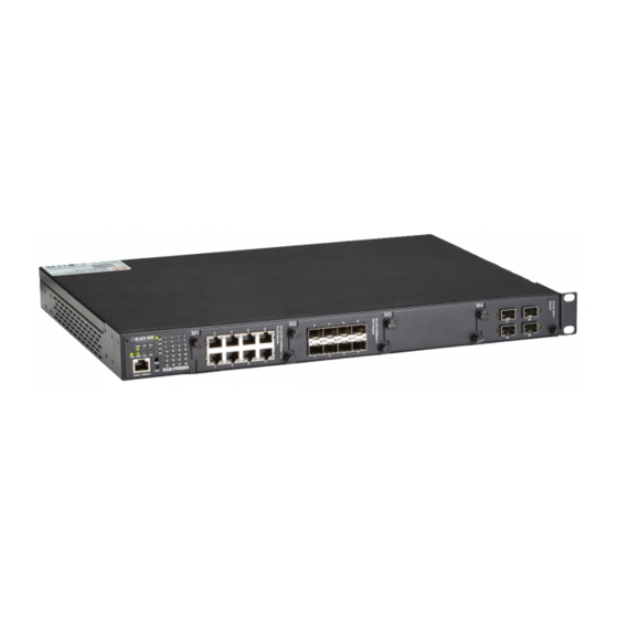
LE2700 Series Hardened Managed Modular Switches
User Manual
This Layer 2 modular rackmount managed Gigabit Ethernet switch
has four module slots that accommodate 8-port 10/100/1000BASE-T RJ-45
and SFP modules, and 4-port 10GE SFP+ and 100-Mbps fiber ST and fiber
SC modules.
Order toll-free in the U.S.: Call 877-877-BBOX (outside U.S. call 724-746-5500)
Customer
FREE technical support 24 hours a day, 7 days a week: Call 724-746-5500 or fax 724-746-0746
Support
Mailing address: Black Box Corporation, 1000 Park Drive, Lawrence, PA 15055-1018
Information
Web site: www.blackbox.com • E-mail: info@blackbox.com
LE2700A
LE2710C
LE2700AE
LE2711C
LE2700UK
LE2720C
LE2721C
LE2722C
LE2731C
Advertisement
Table of Contents

Related Manuals for Black Box LE2700A


Summary of Contents for Black Box LE2700A
- Page 1 Order toll-free in the U.S.: Call 877-877-BBOX (outside U.S. call 724-746-5500) Customer FREE technical support 24 hours a day, 7 days a week: Call 724-746-5500 or fax 724-746-0746 Support Mailing address: Black Box Corporation, 1000 Park Drive, Lawrence, PA 15055-1018 Information Web site: www.blackbox.com • E-mail: info@blackbox.com...
- Page 2 Disclaimer: Black Box Network Services shall not be liable for damages of any kind, including, but not limited to, punitive, consequential or cost of cover damages, resulting from any errors in the product information or specifications set forth in this document and Black Box Network Services may revise this document at any time without notice.
- Page 3 FCC and IC RFI Statements Federal Communications Commission and Industry Canada Radio Frequency Interference Statements This equipment generates, uses, and can radiate radio-frequency energy, and if not installed and used properly, that is, in strict accordance with the manufacturer’s instructions, may cause inter ference to radio communication. It has been tested and found to comply with the limits for a Class A computing device in accordance with the specifications in Subpart B of Part 15 of FCC rules, which are designed to provide reasonable protection against such interference when the equipment is operated in a commercial environment.
-
Page 4: Instrucciones De Seguridad
NOM Statement Instrucciones de Seguridad (Normas Oficiales Mexicanas Electrical Safety Statement) 1. Todas las instrucciones de seguridad y operación deberán ser leídas antes de que el aparato eléctrico sea operado. 2. Las instrucciones de seguridad y operación deberán ser guardadas para referencia futura. 3. -
Page 5: Table Of Contents
Table of Contents Table of Contents 1. Specifications ..................................8 2. Overview ..................................... 10 2.1 Introduction ................................. 10 2.2 Features ..................................10 2.3 What’s Included ................................11 2.4 Hardware Description ..............................12 3. Hardware Installation ................................16 3.1 Rackmount Installation ..............................16 3.2 Module Installation .............................. - Page 6 Table of Contents 5.1.9 Modbus TCP ...............................43 5.1.10 Backup/Restore Configurations .........................43 5.1.11 Firmware Update ...............................44 5.2 DHCP Server ................................44 5.2.1 Basic Settings ..............................44 5.2.2 Dynamic Client List .............................44 5.2.3 Client List ................................44 5.2.4 Relay Agent ................................45 5.3 Port Setting .................................47 5.3.1 Port Control ................................47 5.3.2 Port Trunk ................................48 5.3.3 LACP ..................................49...
- Page 7 Table of Contents 5.8.6 NAS (802.1x) ..............................107 5.9 Alerts ..................................115 5.9.1 Fault Alarm ............................... 115 5.9.2 System Warning ............................... 115 5.10 Monitor and Diag ..............................118 5.10.1 MAC Table ..............................118 5.10.2 Port Statistics ..............................120 5.10.3 Port Mirroring ..............................122 5.10.4 System Log Information ..........................
-
Page 8: Specifications
Chapter 1: Specifications 1. Specifications Ethernet Standards IEEE 802.3 10BASE-T, IEEE 802.3u 100BASE-TX and 100BASE-FX, IEEE 802.3ab 1000BASE-T, IEEE 802.3z 100BASE-X, IEEE 802.3ae 10 Gigabit Ethernet, IEEE 802.3ad LACP (Link Aggregation Control Protocol), IEEE 802.1p COS (Class of Service), IEEE 802.1q VLAN tagging, IEEE 802.1w RSTP (Rapid Spanning Tree Protocol), IEEE 802.1s MSTP (Multiple Spanning Tree Protocol), IEEE 802.1x authentication,... - Page 9 Chapter 1: Specifications Connectors LE2700A, LE2700AE, LE2700UK: RS-232 Serial Console Port: (1) RJ-45 via console cable, 115200 bps, 8, N, 1;| Fault contact: 24-VDC, 1-A relay; LE2710C: (4) 100FX SC; LE2711C: (4) 100FX ST; LE2720C: (8) 10/100/1000BASE-T RJ-45; LE2721C: (8) slots for 100/1000-Mbps SFP modules;...
-
Page 10: Overview
4-port 10GE SFP+ and 100-Mbps fiber ST and fiber SC modules are also available. Figure 2-1. Available models. Part Number Description LE2700A Hardened Managed Modular Switch, 4-Slot Chassis, US LE2700AE Hardened Managed Modular Switch, 4-Slot Chassis, EU LE2700UK... -
Page 11: What's Included
Chapter 2: Overview 2.3 What’s Included Your package should include the following items. If anything is missing or damaged, contact Black Box Technical Support at 724-746-5500 or info@blackbox.com. LE2700A: • LE2700 Series Hardened Managed Modular Switch with power supply • U.S. power cord LE2700AE: •... -
Page 12: Hardware Description
Chapter 2: Overview 2.4 Hardware Description 10-Gigabit or Gigabit Ethernet module installs in slot 4 Figure 2-1. Front panel. Power module slot 1 Power module slot 2 Power module Power module installed in slot 2 installed in slot 1 Figure 2-2. Back panel. 724-746-5500 | blackbox.com Page 12... - Page 13 Chapter 2: Overview On the rear panel of the switch are two panel module slots and one terminal block. The terminal blocks include two power pairs for redundant power supply. Front view 3 45 1 Rear view Table 2-2. LE2700 Series Hardened Managed Modular Switches Components2 Number Component Description...
- Page 14 Chapter 2: Overview B-Ring provides two 10 Gigabit modules and four Gigabit Ethernet modules to meet your demand for high speed. For applica- tions requiring long-distance data transmission, B-Ring also provides several fiber modules to meet your needs. Please refer to the following table for available modules.
- Page 15 Chapter 2: Overview Table 2-5. LE2700 Series Hardened Managed Modular Switches LEDs. Number Color Status Description Green DC power on Green Blinking Upgrading firmware Green DC power module 1 activated Green DC power module 2 activated R.M. Green Ring Master Ring Green Ring enabled...
-
Page 16: Hardware Installation
Chapter 3: Hardware Installation 3. Hardware Installation 3.1 Rackmount Installation The switch comes with two rackmount kits to allow you to fasten the switch to a rack in any environment. Follow the steps below to install the switch to a rack. Step 1: Install left and right front mounting brackets to the switch using 4 M3 screws on each side provided with switch. -
Page 17: Sfp Module (Le2721C)
Chapter 3: Hardware Installation Figure 3-3. RJ-45 module. 3.2.2 SFP Module (LE2721C) Each LE2700 Series Hardened Managed Modular Switches switch supports a maximum of three SFP modules, giving you a total of 24 SFP ports. Follow the steps bellow for installation. Step 1: Switch off the power of the switch. -
Page 18: Power Module
Chapter 3: Hardware Installation Step 3: Switch on the power of the switch. Figure 3-5. 10G SFP+ module. CAUTION: 1. The 10G slot can accommodate a Gigabit or 10G module (LE2722C or LE2731C); therefore, do not insert the LE2722C or LE2731C module in other slots. -
Page 19: Wiring
Chapter 3: Hardware Installation 3.3 Wiring WARNING: Do not disconnect modules or wires unless power has been switched off or the area is known to be non-hazardous. The devices may only be connected to the supply voltage shown on the type plate. ATTENTION: 1. -
Page 20: Connection
Chapter 3: Hardware Installation 3.4 Connection 3.4.1 Cables 1000/100BASE-TX/10BASE-T Pin Assignments The LE2700 Series Hardened Managed Modular Switches switches come with standard Ethernet ports. According to the link type, the switch uses CAT 3, 4, 5,5e UTP cables to connect to any other network devices (PCs, servers, switches, routers, or hubs). Refer to the following table for cable specifications. - Page 21 Chapter 3: Hardware Installation Table 3-4. 10/100BASE-T MDI/MDI-X Pin Assignments. Pin Number MDI port MDI-X port TD+(transmit) RD+(receive) TD-(transmit) RD-(receive) RD+(receive) TD+(transmit) Not used Not used Not used Not used RD-(receive) TD-(transmit) Not used Not used Not used Not used Table 3-5.
-
Page 22: Sfp
Chapter 3: Hardware Installation 3.4.2 SFP The switch comes with fiber optical ports that can connect to other devices using SFP modules. The fiber optical ports are in multimode (0 to 550 m, 850 nm with 50/125-µm, 62.5/125-µm fiber) and single-mode with LC connectors. Remember to connect the TX port of Switch A should be connected to the RX port of Switch B. - Page 23 Chapter 3: Hardware Installation B-Ring B-Ring Figure 3-11. Coupling ring. Dual Homing If you want to connect your ring topology to a RSTP network environment, you can use dual homing. Choose two switches (Switch A & B) from the ring for connecting to the switches in the RSTP network (Ciscos switches). The connection of one of the switches (Switch A or B) will act as the primary path, while the other will act as the backup path that is activated when the primary path connection fails.
- Page 24 Chapter 3: Hardware Installation 3. Once the setting is completed, one of the connections will act as the main path, and the other as the backup path. B-Ring Figure 3-13. B-Chain. 724-746-5500 | blackbox.com Page 24...
-
Page 25: Redundancy
Chapter 4: Redundancy 4. Redundancy Redundancy for minimized system downtime is one of the most important concerns for industrial networking devices. Hence, B-Ring has developed proprietary redundancy technologies including B-Ring, O-RSTP, and Open-Ring featuring faster recovery time than existing redundancy technologies widely used in commercial applications, such as STP, RSTP, and MSTP. B-Ring’s proprietary redundancy technologies not only support different networking topologies, but also assure the reliability of the network. -
Page 26: B-Chain
4.2 B-Chain 4.2.1 Introduction B-Chain is Black Box’s revolutionary network redundancy technology which enhances network redundancy for any backbone networks, providing ease-of-use and maximum fault-recovery swiftness, flexibility, compatibility, and cost-effectiveness in a set of network redundancy topologies. The self-healing Ethernet technology designed for distributed and complex industrial networks enables the network to recover in less than 10 ms for up to 250 switches if at any time a segment of the chain fails. -
Page 27: Stp/Rstp/Mstp
Chapter 4: Redundancy Table 4-3. MRP configuration screen options. Label Description Enable Enables the MRP function Manager Every MRP topology needs a MRP manager. One MRP topology can only have a Manager. If two or more switches are set to be Manager, the MRP topology will fail. - Page 28 Chapter 4: Redundancy STP Port Status This page displays the STP port status for the currently selected switch. Figure 4-3. STP Port Status screen. Table 4-5. STP Port Status screen options. Label Description Port The switch port number to which the following settings will be applied. CIST Role The current STP port role of the CIST port.
- Page 29 Chapter 4: Redundancy Table 4-6. STP statistics screen options. Label Description Port The switch port number to which the following settings will be applied. RSTP The number of RSTP configuration BPDUs received/transmitted on the port. The number of legacy STP configuration BPDUs received/transmitted on the port. The number of (legacy) topology change notification BPDUs received/transmitted on the port.
-
Page 30: Mstp
Chapter 4: Redundancy 4.4.2 MSTP Since the recovery time of STP and RSTP takes seconds, which are unacceptable in some industrial applications, MSTP was devel- oped. The technology supports multiple spanning trees within a network by grouping and mapping multiple VLANs into different spanning-tree instances, known as MSTIs, to form individual MST regions. - Page 31 Chapter 4: Redundancy Table 4-8. MSTI Port Configuration screen options. Label Description Port The switch port number of the corresponding STP CIST (and MSTI) port. Path Cost Configures the path cost incurred by the port. Auto will set the path cost according to the physical link speed by using the 802.1D-recommended values.
- Page 32 Chapter 4: Redundancy Table 4-9. MSTI Configuration screen options. Label Description Configuration Name The name which identifies the VLAN to MSTI mapping. Bridges must share the name and revision (see below), as well as the VLAN-to-MSTI mapping configurations in order to share spanning trees for MSTIs (intra-region).
-
Page 33: Cist
Chapter 4: Redundancy 4.4.3 CIST With the ability to cross regional boundaries, CIST is used by MSTP to communicate with other MSTP regions and with any RSTP and STP single-instance spanning trees in the network. Any boundary port, that is, if it is connected to another region, will auto- matically belongs solely to CIST, even if it is assigned to an MSTI. -
Page 34: Fast Recovery
Chapter 4: Redundancy Table 4-11 (continued). Port Settings screen options. Label Description Restricted TCN When enabled, the port will not propagate received topology change notifications and topology changes to other ports. If set, it will cause temporary disconnection after changes in an active spanning trees topology as a result of persistent incorrectly learned station location information. -
Page 35: Management
Chapter 5: Management 5. Management The switch can be controlled via a built-in Web server that supports Internet Explorer (Internet Explorer 5.0 or above versions) and other Web browsers such as Chrome. Therefore, you can manage and configure the switch easily and remotely. You can also upgrade firmware via a Web browser. -
Page 36: Basic Settings
Chapter 5: Management Figure 5-3. System information. On the right-hand side of the management interface shows links to various settings. You can click on the links to access the con- figuration pages of different functions. 5.1 Basic Settings Basic Settings allow you to configure the basic functions of the switch. 5.1.1 System Information This page shows the general information of the switch. -
Page 37: Admin And Password
Chapter 5: Management Table 5-1 (continued). System information configuration screen options. Label Description System Contact The textual identification of the contact person for this managed node, together with information on how to contact this person. The allowed string length is 0 to 255, and only ASCII characters from 32 to 126 are allowed. -
Page 38: Ip Settings
Chapter 5: Management Table 5-3. Authentication Method Configuration screen options. Label Description Client The management client for which the configuration below applies. Authentication Authentication Method can be set to one of the following values: Method None: authentication is disabled and login is not possible. Local: local user database on the switch is used for authentication. -
Page 39: Ipv6 Settings
Chapter 5: Management 5.1.5 IPv6 Settings You can configure IPv6 information of the switch on the following page. Figure 5-8. IPv6 Configuration screen. Table 5-5. IPv6 Configuration screen options. Label Description Auto Configuration Check to enable IPv6 auto-configuration. If the system cannot obtain the stateless address in time, the configured IPv6 settings will be used. -
Page 40: Ssh
Chapter 5: Management Table 5-6. HTTPS Configuration options. Label Description Mode Indicates the selected HTTPS mode. When the current connection is HTTPS, disabling HTTPS will automati- cally redirect web browser to an HTTP connection. The modes include: Enabled: enable HTTPS. Disabled: disable HTTPS. - Page 41 Chapter 5: Management Table 5-8. LLDP Configuration screen options. Label Description Port The switch port number to which the following settings will be applied. Mode Indicates the selected LLDP mode. Rx only: the switch will not send out LLDP information, but LLDP information from its neighbors will be analyzed. Tx only: the switch will drop LLDP information received from its neighbors, but will send out LLDP information.
- Page 42 Chapter 5: Management Port Statistics This page provides an overview of all LLDP traffic. Two types of counters are shown. Global counters will apply settings to the whole switch stack, while local counters will apply settings to specified switches. Figure 5-13. Port Statistics screen. Global Counters Table 5-10.
-
Page 43: Modbus Tcp
Chapter 5: Management Table 5-11 (continued). Local Counters options. Label Description Age-Outs Each LLDP frame contains information about how long the LLDP information is valid (age-out time). If no new LLDP frame is received during the age-out time, the LLDP information will be removed, and the value of the age-out counter will be incremented. -
Page 44: Firmware Update
Chapter 5: Management 5.1.11 Firmware Update This page allows you to update the firmware of the switch. Figure 5-16. Firmware Update screen. 5.2 DHCP Server The switch provides DHCP server functions. By enabling DHCP, the switch will become a DHCP server and dynamically assigns IP addresses and related IP information to network clients. -
Page 45: Relay Agent
Chapter 5: Management Figure 5-19. DHCP Client Lists screen. 5.2.4 Relay Agent DHCP relay is used to forward and transfer DHCP messages between the clients and the server when they are not in the same subnet domain. You can configure the function in this page. Figure 5-20. - Page 46 Chapter 5: Management Table 5-13 (continued). DHCP Relay Configuration screen options. Label Description Relay Information Indicates the policies to be enforced when receiving DHCP relay information. When DHCP relay information Policy mode is enabled, if the agent receives a DHCP message that already contains relay agent information, it will enforce the policy.
-
Page 47: Port Setting
Chapter 5: Management Table 5-15. Client Statistics screen options. Label Description Transmit to Client The number of packets relayed from the server to the client. Transmit Error The number of packets with errors when being sent to servers. Receive from Client The number of packets received from the server. -
Page 48: Port Trunk
Chapter 5: Management Table 5-16 (continued). Port Configuration screen options. Label Description Flow Control When Auto is selected for the speed, the flow control will be negotiated to the capacity advertised by the link partner. When a fixed-speed setting is selected, that is what is used. Current Rx indicates whether pause frames on the port are obeyed, and Current Tx indicates whether pause frames on the port are transmitted. -
Page 49: Lacp
Chapter 5: Management Figure 5-25. Aggregation Group Configuration screen. Table 5-18. Aggregation Group Configuration screen options. Label Description Group ID Indicates the ID of each aggregation group. Normal means no aggregation. Only one group ID is valid per port. Port Members Lists each switch port for each group ID. - Page 50 Chapter 5: Management Table 5-19. LACP Port Configuration screen options. Label Description Port Indicates the ID of each aggregation group. Normal indicates there is no aggregation. Only one group ID is valid per port. LACP Enabled Lists each switch port for each group ID. Check to include a port in an aggregation, or clear the box to remove the port from the aggregation.
- Page 51 Chapter 5: Management Figure 5-28. LACP Status screen. Table 5-21. LACP Status screen options. Label Description Port Switch port number LACP Yes means LACP is enabled and the port link is up. No means LACP is not enabled or the port link is down. Backup means the port cannot join in the aggregation group unless other ports are removed.
-
Page 52: Loop Ground
Chapter 5: Management 5.3.4 Loop Gourd This feature prevents loop attack. When receiving loop packets, the port will be disabled automatically, preventing the loop attack from affecting other network devices. Figure 5-30. Loop Gourd screen. Table 5-23. Loop Gourd screen options. Label Description Enable Loop Protection Activate loop protection functions (as a whole) -
Page 53: Vlan
Chapter 5: Management 5.4 VLAN 5.4.1 VLAN Membership You can view and change VLAN membership configurations for a selected switch stack in this page. Up to 64 VLANs are supported. This page allows for adding and deleting VLANs as well as adding and deleting port members of each VLAN. Figure 5-32. -
Page 54: Port Configurations
Chapter 5: Management 5.4.2 Port Configurations This page allows you to set up VLAN ports individually. Figure 5-33. VLAN Port Configuration screen. Table 5-26. VLAN Port Configuration screen options. Label Description Ethertype for customer This field specifies the Ether type used for custom S-ports. This is a global setting for all custom S-Ports S-ports. - Page 55 Chapter 5: Management Introduction of Port Types Below is a detailed description of each port type, including Unaware, C-port, S-port, and S-custom-port. Table 5-27. Port types. Ingress Action Egress Action Unaware When the port receives untagged frames, an untagged The TPID of a frame transmitted by frame obtains a tag (based on PVID) and is forwarded.
- Page 56 Chapter 5: Management Figure 5-34. 724-746-5500 | blackbox.com Page 56...
- Page 57 Chapter 5: Management Figure 5-35. 724-746-5500 | blackbox.com Page 57...
- Page 58 Chapter 5: Management Examples of VLAN Settings VLAN Access Mode: Figure 5-36. Switch A, Port 7 is VLAN Access mode = Untagged 20 Port 8 is VLAN Access mode = Untagged 10 Below are the switch settings. Figure 5-37. 724-746-5500 | blackbox.com Page 58...
- Page 59 Chapter 5: Management Figure 5-38. VLAN 1Q Trunk Mode: Figure 5-39. Switch B, Port 1 = VLAN 1Qtrunk mode = tagged 10, 20 Port 2 = VLAN 1Qtrunk mode = tagged 10, 20 Below are the switch settings. Figure 5-40. 724-746-5500 | blackbox.com Page 59...
- Page 60 Chapter 5: Management Figure 5-41. VLAN Hybrid Mode: Port 1 VLAN Hybrid mode = untagged 10 Tagged 10, 20 Below are the switch settings. Figure 5-42. Figure 5-43. 724-746-5500 | blackbox.com Page 60...
- Page 61 Chapter 5: Management VLAN QinQ Mode: VLAN QinQ mode is usually adopted when there are unknown VLANs, as shown in the figure below. VLAN “X” = Unknown VLAN Figure 5-44. VLAN QinQ mode. Port 1 VLAN Settings: Figure 5-45. VLAN Settings scren. Figure 5-46.
-
Page 62: Private Vlan
Chapter 5: Management VLAN ID Settings When setting the management VLAN, only the same VLAN ID port can be used to control the switch. VLAN Settings: Figure 5-47. 5.4.3 Private VLAN The private VLAN membership configuration for the switch can be monitored and modified here. Private VLANs can be added or deleted here. - Page 63 Chapter 5: Management Table 5-28. Private VLAN Membership Configuration screen options. Label Description Delete Check to delete the entry. It will be deleted during the next save. Private VLAN ID Indicates the ID of this particular private VLAN. MAC Address The MAC address for the entry.
-
Page 64: Snmp
Chapter 5: Management 5.5 SNMP 5.5.1 SNMP System Configurations Figure 5-50. SNMP system configuration screen. Table 5-30. SNMP System Configuration screen options. Label Description Mode Indicates existing SNMP mode. Possible modes include: Enabled: enable SNMP mode Disabled: disable SNMP mode Version Indicates the supported SNMP version. - Page 65 Chapter 5: Management Figure 5-51. SNMP Trap Configuration screen. Table 5-31. SNMP Trap Configuration screen options. Label Description Trap Mode Indicates existing SNMP trap mode. Possible modes include: Enabled: enable SNMP trap mode Disabled: disable SNMP trap mode Trap Version Indicates the supported SNMP trap version.
-
Page 66: Snmp Community Configurations
Chapter 5: Management Table 5-31 (continued). SNMP Trap Configuration screen options. Label Description Trap Inform Timeout Configures the SNMP trap inform timeout. The allowed range is 0 to 2147. (seconds) Trap Inform Retry Times Configures the retry times for SNMP trap inform. The allowed range is 0 to 255. 5.5.2 SNMP Community Configurations This page allows you to configure SNMPv3 community table. - Page 67 Chapter 5: Management Table 5-33. SNMPv3 Users Configuration screen options. Label Description Delete Check to delete the entry. It will be deleted during the next save. Engine ID An octet string identifying the engine ID that this entry should belong to. The string must contain an even number between 10 and 64 hexadecimal digits, but all-zeros and all-'F's are not allowed.
-
Page 68: Snmp Group Configurations
Chapter 5: Management 5.5.4 SNMP Groups Configuration This page allows you to configure SNMPv3 group table. The entry index keys are Security Model and Security Name. Figure 5-54. SNMPv3 Groups Configuration screen. Table 5-34. SNMPv3 Groups Configuration screen options. Label Description Delete Check to delete the entry. -
Page 69: Snmp Access Configurations
Chapter 5: Management Table 5-35. SNMPv3 Views Configuration screen options. Label Description Delete Check to delete the entry. It will be deleted during the next save. View Name A string identifying the view name that this entry should belong to. The allowed string length is 1 to 32, and only ASCII characters from 33 to 126 are allowed. -
Page 70: Traffic Prioritization
Chapter 5: Management 5.6 Traffic Prioritization 5.6.1 Storm Control There is a unicast storm rate control, multicast storm rate control, and a broadcast storm rate control. These only affect flooded frames, i.e. frames with a (VLAN ID, DMAC) pair not present on the MAC Address table. The rate is 2^n, where n is equal to or less than 15, or "No Limit". -
Page 71: Port Classification
Chapter 5: Management 5.6.2 Port Classification QoS is an acronym for Quality of Service. It is a method to achieve efficient bandwidth utilization between individual applications or protocols. Figure 5-58. QoS Ingres Port Classification screen. Table 5-38. QoS Ingres Port Classification screen options. Label Description Port... -
Page 72: Port Tag Remaking
Chapter 5: Management Table 5-38 (continued). QoS Ingres Port Classification screen options. Label Description Controls the default PCP value. All frames are classified to a PCP value. If the port is VLAN aware and the frame is tagged, then the frame is classified to the PCP value in the tag. -
Page 73: Port Dscp
Chapter 5: Management Table 5-39. QoS Egress Port Tag Remarking screen options. Label Description Port The switch port number to which the following settings will be applied. Click on the port number to configure tag remarking. Mode Enable or disable the storm control status for the given frame type. Shows the tag remarking mode for this port. -
Page 74: Port Policing
Chapter 5: Management Table 5-40 (continued). QoS Egress Port DSCP Configuration screen options. Label Description Egress Port egress rewriting can be one of the following options: Disable: no Egress rewrite Enable: rewrite enabled without remapping Remap DP Unaware: DSCP from the analyzer is remapped and the frame is remarked with a remapped DSCP value. -
Page 75: Queue Policing
Chapter 5: Management 5.6.6 Queue Policing This page allows you to configure Queue Policer settings for all switch ports. Figure 5-62. QoS Ingress Queue Policers screen. Table 5-42. QoS Ingress Queue Policers screen options. Label Description Port The port number for which the configuration below applies. Enable(E) Check to enable queue policer for individual switch ports. -
Page 76: Qos Egress Port Scheduler And Shapers
Chapter 5: Management 5.6.7 QoS Egress Port Scheduler and Shapers This page allows you to configure Scheduler and Shapers for a specific port. Strict Priority Figure 5-63. Strict Priority screen. Table 5-43. Strict Priority screen options. Label Description Scheduler Mode Controls whether the scheduler mode is Strict Priority or Weighted on this switch port. - Page 77 Chapter 5: Management Weighted Figure 5-64. QoS Egress Port Scheduler and Shapers Port 1. Table 5-44. QoS Egress Port Scheduler and Shapers Port 1 screen options. Label Description Scheduler Mode Controls whether the scheduler mode is Strict Priority or Weighted on this switch port. Queue Shaper Enable Check to enable queue shaper for individual switch ports.
-
Page 78: Port Scheduled
Chapter 5: Management Table 5-44 (continued). QoS Egress Port Scheduler and Shapers Port 1 screen options. Label Description Port Shaper Rate Configures the rate of each port shaper. The default value is 500. This value is restricted to 100 to 1000000 when the Unit is kbps, and it is restricted to 1 to 3300 when the Unit is Mbps. -
Page 79: Dscp Based Qos
Chapter 5: Management Table 5-46. QoS Egress Port Shapers screen options. Label Description Port The switch port number to which the following settings will be applied. Click on the port number to configure the shapers. Mode Shows disabled or actual queue shaper rate - e.g. “800 Mbps.” Shows disabled or actual port shaper rate - e.g. -
Page 80: Dscp Translation
Chapter 5: Management 5.6.11 DSCP Translation This page allows you to configure basic QoS DSCP translation settings for all switches. DSCP translation can be done in Ingress or Egress. Figure 5-68. DSCP Translation screen. Table 5-48. DSCP Translation screen options. Label Description DSCP... -
Page 81: Qos Control List
Chapter 5: Management Table 5-49. DSCP Classification screen options. Label Description QoS Class Actual QoS class Actual Drop Precedence Level DSCP Select the classified DSCP value (0–63) 5.6.13 QoS Control List This page allows you to edit or insert a single QoS control entry at a time. A QCE consists of several parameters. These parameters vary with the frame type you select. - Page 82 Chapter 5: Management Table 5-50. QCE Configuration screen options. Label Description Port Check to include the port in the QCL entry. By default, all ports are included. Members Key configurations include: Parameters Tag: value of tag, can be Any, Untag or Tag. VID: valid value of VLAN ID, can be any value from 1 to 4095 Any: user can enter either a specific value or a range of VIDs.
-
Page 83: Qos Counters
Chapter 5: Management Table 5-50 (continued). QCE Configuration screen options. Label Description Action Parameters Class QoS class: (0–7) or Default Valid Drop Precedence Level value can be (0–1) or Default. Valid DSCP value can be (0–63, BE, CS1–CS7, EF or AF11–AF43) or Default. Default means that the default classified value is not modified by this QCE. -
Page 84: Multicast
Chapter 5: Management Table 5-52. QoS Control List Status screen options. Label Description User Indicates the QCL user QCE# Indicates the index of QCE Frame Type Indicates the type of frame to look for incoming frames. Possible frame types are: Any: the QCE will match all frame type. -
Page 85: Vlan Configurations Of Igmp Snooping
Chapter 5: Management Table 5-53. IGMP Snooping Configuration screen options. Label Description Snooping Enabled Check to enable global IGMP snooping. Unregistered Check to enable unregistered IPMC traffic flooding. IPMCv4Flooding enabled Router Port Specifies which ports act as router ports. A router port is a port on the Ethernet switch that leads towards the Layer 3 multicast device or IGMP querier. -
Page 86: Igmp Snooping Status
Chapter 5: Management Table 5-54. IGMP Snooping VLAN Configuration screen options. Label Description Delete Check to delete the entry. The designated entry will be deleted during the next save. VLAN ID The VLAN ID of the entry. IGMP Snooping Enable Check to enable IGMP snooping for individual VLAN. -
Page 87: Groups Igmp Snooping Information
Chapter 5: Management 5.7.4 Groups Information of IGMP Snooping Entries in the IGMP Group Table are shown on this page. The IGMP Group Table is sorted first by VLAN ID, and then by group. Figure 5-76. IGMP Snooping Group Information screen. Table 5-56. -
Page 88: Device Binding
Chapter 5: Management Table 5-57. Remote Control Security Configuration screen options. Label Description Port Port number of the remote client IP Address IP address of the remote client. 0.0.0.0 means “any IP.” Check to enable management via a Web interface Telnet Check to enable management via a Telnet interface SNMP... - Page 89 Chapter 5: Management Table 5-58 (continued). Device Binding screen options. Label Description DDoS Prevention Status Indicates DDOS prevention status. Possible statuses are: ---: disable Analyzing: analyzes packet throughput for initialization Running: analysis completes and ready for next move Attacked: DDOS attacks occur Device IP Address Specifies IP address of the device Device MAC Address...
- Page 90 Chapter 5: Management Table 5-60. Alive Check screen options. Label Description Link Change Disables or enables the port Only log it Simply sends logs to the log server Shut Down the Port Disables the port Reboot Device Disables or enables PoE power DDoS Prevention This page provides DDOS Prevention configurations.
- Page 91 Chapter 5: Management Table 5-61 (continued). DDOS Prevention screen options. Label Description Filter If packet type is UDP (or TCP), please choose the socket direction (Destination/Source). Action Indicates the action to take when DDOS attacks occur. Possible actions are: ---: no action Blocking 1 minute: blocks the forwarding for 1 minute and log the event Blocking 10 minute: blocks the forwarding for 10 minutes and log the event Blocking: blocks and logs the event...
-
Page 92: Acl Ports
Chapter 5: Management Stream Check This page allows you to configure stream check settings. Figure 5-83. Stream Check screen. Table 5-63. Stream Check screen options. Label Description Mode Enables or disables stream monitoring of the port. Action Indicates the action to take when the stream gets low. Possible actions are: ---: no action Log it: simply logs the event 5.8.3 ACL Ports... - Page 93 Chapter 5: Management Table 5-64. ACL Ports Configuration screen options. Label Description Port The switch port number to which the following settings will be applied. Policy ID Select to apply a policy to the port. The allowed values are 1 to 8. The default value is 1. Action Select to Permit to permit or Deny to deny forwarding.
- Page 94 Chapter 5: Management Table 5-65. ACL Rate Limiter Configuration screen options. Label Description Rate Limiter ID The rate limiter ID for the settings contained in the same row. Rate The rate unit is packet per second (pps), which can be configured as 1, 2, 4, 8, 16, 32, 64, 128, 256, 512, 1K, 2K, 4K, 8K, 16K, 32K, 64K, 128K, 256K, 512K, or 1024K.
- Page 95 Chapter 5: Management Table 5-66 (continued). ACE Configuration screen. Label Description Rate Limiter Specifies the rate limiter in number of base units. The allowed range is 1 to 15. Disabled means the rate limiter operation is disabled. Port Copy Frames matching the ACE are copied to the port number specified here. The allowed range is the same as the switch port number range.
- Page 96 Chapter 5: Management Table 5-67 (continued). MAC Parameters screen options. Label Description DMAC Value When Specific is selected for the DMAC filter, you can enter a specific destination MAC address. The legal format is “xx-xx-xx-xx-xx-xx.” Frames matching the ACE will use this DMAC value. Figure 5-88.
- Page 97 Chapter 5: Management Table 5-69. IP Parameters screen options. Label Description IP Protocol Filter Specifies the IP protocol filter for the ACE Any: no IP protocol filter is specified (“don't-care”). Specific: if you want to filter a specific IP protocol filter with the ACE, choose this value. A field for entering an IP protocol filter appears.
- Page 98 Chapter 5: Management Figure 5-90. ARP Parameters screen. Table 5-70. ARP Parameters screen options. Label Description ARP/RARP Specifies the available ARP/RARP opcode (OP) flag for the ACE Any: no ARP/RARP OP flag is specified (OP is “don't-care”). ARP: frame must have ARP/RARP opcode set to ARP RARP: frame must have ARP/RARP opcode set to RARP.
- Page 99 Chapter 5: Management Table 5-70 (continued). ARP Parameters screen options. Label Description ARP SMAC Specifies whether frames will meet the action according to their sender hardware address field (SHA) set- Match tings. 0: ARP frames where SHA is not equal to the SMAC address 1: ARP frames where SHA is equal to the SMAC address Any: any value is allowed (“don't-care”).
- Page 100 Chapter 5: Management Table 5-71. ICMP Parameters screen options. Label Description ICMP Type Filter Specifies the ICMP filter for the ACE Any: no ICMP filter is specified (ICMP filter status is "don't-care"). Specific: if you want to filter a specific ICMP filter with the ACE, you can enter a specific ICMP value. A field for entering an ICMP value appears.
-
Page 101: Aaa
Chapter 5: Management Table 5-72 (continued). TCP Parameters and UDP Parameters screens options. Label Description TCP/UDP Specifies the TCP/UDP destination filter for the ACE Destination Filter Any: no TCP/UDP destination filter is specified (TCP/UDP destination filter status is "don't-care"). Specific: if you want to filter a specific TCP/UDP destination filter with the ACE, you can enter a specific TCP/ UDP destination value. -
Page 102: Radius
Chapter 5: Management Table 5-73. Authentication Server Configuration screen options. Label Description Timeout The timeout, which can be set to a number between 3 and 3600 seconds, is the maximum time to wait for a reply from a server. If the server does not reply within this time frame, we will consider it to be dead and continue with the next enabled server (if any). - Page 103 Chapter 5: Management Figure 5-95. RADIUS Accounting Server Configuration screen. Figure 5-75. RADIUS Accounting Server Configuration screen options. Label Description The RADIUS accounting server number for which the configuration below applies. Enabled Check to enable the RADIUS accounting server. IP Address The IP address or hostname of the RADIUS accounting server.
- Page 104 Chapter 5: Management Table 5-76 (continued). RADIUS Authentication Server Status Overview screen options. Label Description Status The current status of the server. This field has one of the following values: Disabled: the server is disabled. Not Ready: the server is enabled, but IP communication is not yet up and running. Ready: the server is enabled, IP communications are built, and the RADIUS module is ready to accept access attempts.
- Page 105 Chapter 5: Management Authentication and Accounting Server Statistics The statistics map closely to those specified in RFC4668 - RADIUS Authentication Client MIB. Use the server drop-down list to switch between the backend servers to show related details. Figure 5-98. RADIUS Authentication Statistics for Server #1 screen. Table 5-78.
- Page 106 Chapter 5: Management Table 5-78 (continued). RADIUS Authentication Statistics for Server #1 screen options. Label Description Other Info This section contains information about the state of the server and the latest round-trip time. Figure 5-99. RADIUS Accounting Statistics for Server #1 screen. Table 5-79.
-
Page 107: Nas (802.1X)
Chapter 5: Management Table 5-79 (continued). RADIUS Accounting Statistics for Server #1 screen options. Label Description Other info This section contains information about the state of the server and the latest round-trip time. 5.8.6 NAS (802.1x) This page allows you to configure the IEEE 802.1X and MAC-based authentication system and port settings. The IEEE 802.1X standard defines a port-based access control procedure that prevents unauthorized access to a network by requiring users to first submit credentials for authentication. - Page 108 Chapter 5: Management Overview of MAC-Based Authentication Unlike 802.1X, MAC-based authentication is not a standard, but merely a best-practices method adopted by the industry. In MAC- based authentication, users are called clients, and the switch acts as the supplicant on behalf of clients. The initial frame (any kind of frame) sent by a client is snooped by the switch, which in turn uses the client's MAC address as both username and password in the subsequent EAP exchange with the RADIUS server.
- Page 109 Chapter 5: Management Table 5-80. Network Access Server Configuration screen options. Label Description Mode Indicates if 802.1X and MAC-based authentication is globally enabled or disabled on the switch. If globally disabled, all ports are allowed to forward frames. Reauthentication If checked, clients are reauthenticated after the interval specified by the Reauthentication Period. Enabled Reauthentication for 802.1X-enabled ports can be used to detect if a new device is plugged into a switch port.
- Page 110 Chapter 5: Management Table 5-80 (continued). Network Access Server Configuration screen options. Label Description Admin State Port-based 802.1X (continued) In an 802.1X network environment, the user is called the supplicant, the switch is the authenticator, and the RADIUS server is the authentication server. The authenticator acts as the man-in-the-middle, forwarding requests and responses between the supplicant and the authentication server.
- Page 111 Chapter 5: Management Table 5-80 (continued). Network Access Server Configuration screen options. Label Description Admin State In Multi 802.1X, it is not possible to use the multicast BPDU MAC address as the destination MAC address (continued) for EAPOL frames sent from the switch to the supplicant, since that would cause all supplicants attached to the port to reply to requests sent from the switch.
- Page 112 Chapter 5: Management Table 5-80 (continued). Network Access Server Configuration screen options. Label Description Port State The current state of the port. It can undertake one of the following values: Globally Disabled: NAS is globally disabled. Link Down: NAS is globally enabled, but there is no link on the port. Authorized: the port is in Force Authorized or a single-supplicant mode and the supplicant is authorized.
- Page 113 Chapter 5: Management This page provides detailed IEEE 802.1X statistics for a specific switch port using port-based authentication. For MAC-based ports, only selected backend server (RADIUS Authentication Server) statistics is showed. Use the port drop-down list to select which port details to be displayed.
- Page 114 Chapter 5: Management Table 5-82 (continued). NAS Statistics Port 2 screen options. Label Description Backend Server These backend (RADIUS) frame counters are available for the following administrative states: Counters • 802.1X • MAC-based Auth. Last Supplicant/ Information about the last supplicant/client that attempts to authenticate. This information is available Client Info for the following administrative states: •...
-
Page 115: Alerts
Chapter 5: Management 5.9 Alerts 5.9.1 Fault Alarm When any selected fault event happens, the Fault LED on the switch panel will light up and the electric relay will signal at the same time. Figure 5-103. Port Link Down/Broken and Fault Alarm screens. 5.9.2 System Warning SYSLOG Setting The SYSLOG is a protocol that transmits event notifications across networks. - Page 116 Chapter 5: Management SMTP Setting SMTP (Simple Mail Transfer Protocol) is a protocol for transmitting e-mails across the Internet. For more information, refer to RFC 821—Simple Mail Transfer Protocol. Figure 5-105. SMTP Setting screen. Table 5-84. SMTP Setting screen options. Label Description E-mail Alarm...
- Page 117 Chapter 5: Management Event Selection SYSLOG and SMTP are two warning methods supported by the system. Check the corresponding box to enable the system event warning method you want. Please note that the checkbox cannot be checked when SYSLOG or SMTP is disabled. Figure 5-106.
-
Page 118: Monitor And Diag
Chapter 5: Management 5.10 Monitor and Diag 5.10.1 MAC Table The MAC address table can be configured on this page. You can set timeouts for entries in the dynamic MAC table and configure the static MAC table here. Figure 5-107. MAC Address Table Configuration and Static Mac Table Configuration screens. Aging Configuration By default, dynamic entries are removed from the MAC after 300 seconds. - Page 119 Chapter 5: Management Table 5-86. MAC Table Learning screen options. Label Description Auto Learning is done automatically as soon as a frame with unknown SMAC is received. Disable No learning is done. Secure Only static MAC entries are learned, all other frames are dropped. NOTE: Make sure the link used for managing the switch is added to the static Mac table before changing to secure learning mode;...
-
Page 120: Port Statistics
Chapter 5: Management The >> will use the last entry of the currently displayed VLAN/MAC address pairs as a basis for the next lookup. When it reaches the end, the text “no more entries” is shown in the displayed table. Use the |<< button to start over. Figure 5-110. - Page 121 Chapter 5: Management Table 5-89. Port Statistics Overview screen options. Label Description Port The switch port number to which the following settings will be applied. Packets The number of received and transmitted packets per port. Bytes The number of received and transmitted bytes per port. Errors The number of frames received in error and the number of incomplete transmissions per port.
-
Page 122: Port Mirroring
Chapter 5: Management Table 5-90. Detailed Port Statistics Port 1 screen options. Label Description Rx and Tx Packets The number of received and transmitted (good and bad) packets. Rx and Tx Octets The number of received and transmitted (good and bad) bytes, including FCS, except framing bits. Rx and Tx Unicast The number of received and transmitted (good and bad) unicast packets. -
Page 123: System Log Information
Chapter 5: Management Figure 5-113. MIrror Configuration screen. Table 5-91. MIrror Configuration screen options. Label Description Port The switch port number to which the following settings will be applied. Mode Drop-down list for selecting a mirror mode. Rx only: only frames received on this port are mirrored to the mirror port. Frames transmitted are not mirrored. -
Page 124: Cable Diagnostics
Chapter 5: Management Table 5-92. System Log Information screen options. Label Description The ID (>= 1) of the system log entry. Level The level of the system log entry. The following level types are supported: Info: provides general information Warning: provides warning for abnormal operation Error: provides error message All: enables all levels Time... -
Page 125: Sfp Monitor
Chapter 5: Management Table 5-93. SVeriPHY Cable Diagnostics screen options. Label Description Port The port for which VeriPHY Cable Diagnostics is requested. Cable Status Port: port number Pair: the status of the cable pair Length: the length (in meters) of the cable pair 5.10.6 SFP Monitor SFP modules with DDM (Digital Diagnostic Monitoring) function can measure the temperature of the apparatus, helping you monitor the status of connection and detect errors immediately. - Page 126 Chapter 5: Management After you press Start, five ICMP packets will be transmitted, and the sequence number and roundtrip time will be displayed upon reception of a reply. The page refreshes automatically until responses to all packets are received, or until a timeout occurs. PING6 server ::10.10.132.20 64 bytes from ::10.10.132.20: icmp_seq=0, time=0ms 64 bytes from ::10.10.132.20: icmp_seq=1, time=0ms...
-
Page 127: Synchronization
Chapter 5: Management 5.11 Synchronization MAC-based Authentication This page allows you to configure and examine current PTP clock settings. PTP External Clock Mode Figure 5-119. PTP External Clock Mode screen. Table 5-95. PTP External Clock Mode screen options. Label Description One_pps_mode The box allows you to select One_pps_mode configurations. - Page 128 Chapter 5: Management Table 5-96. PTP Clock Configuration screen options. Label Description Delete Check this box and click Save to delete the clock instance. Clock Instance Indicates the instance of a particular clock instance [0..3] Click on the clock instance number to edit the clock details Device Type Indicates the type of the clock instance.
- Page 129 Chapter 5: Management Table 5-97. Power Over Ethernet Status screen options. Label Description Local Port The switch port number to which the following settings will be applied. PD Class Each power device is classified according to the class that defines the maximum power consumed by the PD.
-
Page 130: Troubleshooting
Chapter 5: Management 5.12 Troubleshooting 5.12.1 Factory Defaults You can reset the configuration of the stack switch on this page. Only the IP configuration is retained. Figure 5-123. Factory default prompt screen. Table 5-98. Factory default prompt screen options. Label Description Click to reset the configuration to factory defaults. - Page 131 Chapter 5: Management Follow the steps below to access the console via RS-232 serial cable. Step 1: On Windows desktop, click on Start -> Programs -> Accessories -> Communications -> HyperTerminal. Figure 5-125. HyperTerminal screen. 724-746-5500 | blackbox.com Page 131...
- Page 132 Chapter 5: Management Step 2: Input a name for the new connection. Figure 5-126. Connection Description screen. Step 3: Select a COM port in the drop-down list. Figure 5-127. COM port screen. 724-746-5500 | blackbox.com Page 132...
- Page 133 Chapter 5: Management Step 4: A pop-up window that indicates COM port properties appears, including bits per second, data bits, parity, stop bits, and flow control. Figure 5-128. COM Properties screen. Step 5: The console login screen will appear. Use the keyboard to enter the Username and Password (same as the password for Web browsers), then press Enter.
- Page 134 Chapter 5: Management CLI Management by Telnet You can can use TELNETto configure the switch. The default values are: IP Address: 192.168.10.1 Subnet Mask: 255.255.255.0 Default Gateway: 192.168.10.254 User Name: admin Password: admin Follow the steps below to access the console via Telnet. Step 1: Telnet to the IP address of the switch from the Run window by inputting commands (or from the MS-DOS prompt) as below.
- Page 135 Chapter 5: Management Commander Groups Figure 5-132. Command Groups screen. System System> Configuration [all] [<port_list>] Reboot Restore Default [keep_ip] Contact [<contact>] Name [<name>] Location [<location>] Description [<description>] Password <password> Username [<username>] Timezone [<offset>] Log [<log_id>] [all|info|warning|error] [clear] 724-746-5500 | blackbox.com Page 135...
- Page 136 Chapter 5: Management IP> Configuration DHCP [enable|disable] Setup [<ip_addr>] [<ip_mask>] [<ip_router>] [<vid>] Ping <ip_addr_string> [<ping_length>] SNTP [<ip_addr_string>] Port port> Configuration [<port_list>] [up|down] Mode [<port_list>] [auto|10hdx|10fdx|100hdx|100fdx|1000fdx|sfp_auto_ams] Flow Control [<port_list>] [enable|disable] State [<port_list>] [enable|disable] MaxFrame [<port_list>] [<max_frame>] Power [<port_list>] [enable|disable|actiphy|dynamic] Excessive [<port_list>] [discard|restart] Statistics [<port_list>] [<command>] [up|down] VeriPHY [<port_list>] SFP [<port_list>]...
- Page 137 Chapter 5: Management Add <vid>|<name> [<ports_list>] Forbidden Add <vid>|<name> [<port_list>] Delete <vid>|<name> Forbidden Delete <vid>|<name> Forbidden Lookup [<vid>] [(name <name>)] Lookup [<vid>] [(name <name>)] [combined|static|nas|all] Name Add <name> <vid> Name Delete <name> Name Lookup [<name>] Status [<port_list>] [combined|static|nas|mstp|all|conflicts] Private VLAN PVLAN>...
- Page 138 Chapter 5: Management Security Switch SSH Security/switch/ssh> Configuration Mode [enable|disable] Security Switch HTTPS Security/switch/ssh> Configuration Mode [enable|disable] Security Switch RMON Security/switch/rmon> Statistics Add <stats_id> <data_source> Statistics Delete <stats_id> Statistics Lookup [<stats_id>] History Add <history_id> <data_source> [<interval>] [<buckets>] History Delete <history_id> History Lookup [<history_id>] Alarm Add <alarm_id>...
- Page 139 Chapter 5: Management Authenticate [<port_list>] [now] Statistics [<port_list>] [clear|eapol|radius] Security Network ACL Security/Network/ACL> Configuration [<port_list>] Action [<port_list>] [permit|deny] [<rate_limiter>][<port_redirect>] [<mirror>] [<logging>] [<shut- down>] Policy [<port_list>] [<policy>] Rate [<rate_limiter_list>] [<rate_unit>] [<rate>] Add [<ace_id>] [<ace_id_next>][(port <port_list>)] [(policy <policy> <policy_bitmask>)][<tagged>] [<vid>] [<tag_prio>] [<dmac_type>][(etype [<etype>] [<smac>] [<dmac>]) | (arp [<sip>] [<dip>] [<smac>] [<arp_opcode>] [<arp_flags>]) | (ip [<sip>] [<dip>] [<protocol>] [<ip_flags>]) | (icmp [<sip>] [<dip>] [<icmp_type>] [<icmp_code>] [<ip_flags>]) |...
- Page 140 Chapter 5: Management Security Network AAA Security/Network/AAA> Configuration Timeout [<timeout>] Deadtime [<dead_time>] RADIUS [<server_index>] [enable|disable] [<ip_addr_string>] [<secret>] [<server_port>] ACCT_RADIUS [<server_index>] [enable|disable] [<ip_addr_string>] [<secret>] [<server_port>] Statistics [<server_index>] STP> Configuration Version [<stp_version>] Non-certified release, v Txhold [<holdcount>]lt 15:15:15, Dec 6 2007 MaxAge [<max_age>] FwdDelay [<delay>] bpduFilter [enable|disable] bpduGuard [enable|disable]...
- Page 141 Chapter 5: Management Aggr Aggr> Configuration Add <port_list> [<aggr_id>] Delete <aggr_id> Lookup [<aggr_id>] Mode [smac|dmac|ip|port] [enable|disable] LACP LACP> Configuration [<port_list>] Mode [<port_list>] [enable|disable] Key [<port_list>] [<key>] Role [<port_list>] [active|passive] Status [<port_list>] Statistics [<port_list>] [clear] LLDP LLDP> Configuration [<port_list>] Mode [<port_list>] [enable|disable] Statistics [<port_list>] [clear] Info [<port_list>] PoE>...
- Page 142 Chapter 5: Management QoS> DSCP Map [<dscp_list>] [<class>] [<dpl>] DSCP Translation [<dscp_list>] [<trans_dscp>] DSCP Trust [<dscp_list>] [enable|disable] DSCP Classification Mode [<dscp_list>] [enable|disable] DSCP Classification Map [<class_list>] [<dpl_list>] [<dscp>] DSCP EgressRemap [<dscp_list>] [<dpl_list>] [<dscp>] Storm Unicast [enable|disable] [<packet_rate>] Storm Multicast [enable|disable] [<packet_rate>] Storm Broadcast [enable|disable] [<packet_rate>] QCL Add [<qce_id>] [<qce_id_next>] [<port_list>]...
- Page 143 Chapter 5: Management Dot1x Dot1x> Configuration [<port_list>] Mode [enable|disable] State [<port_list>] [macbased|auto|authorized|unauthorized] Authenticate [<port_list>] [now] Reauthentication [enable|disable] Period [<reauth_period>] Timeout [<eapol_timeout>] Statistics [<port_list>] [clear|eapol|radius] Clients [<port_list>] [all|<client_cnt>] Agetime [<age_time>] Holdtime [<hold_time>] IGMP IGMP> Configuration [<port_list>] Mode [enable|disable] State [<vid>] [enable|disable] Querier [<vid>] [enable|disable] Fastleave [<port_list>] [enable|disable] Router [<port_list>] [enable|disable]...
- Page 144 Chapter 5: Management ACL> Configuration [<port_list>] Action [<port_list>] [permit|deny] [<rate_limiter>] [<port_copy>] [<logging>] [<shutdown>] Policy [<port_list>] [<policy>] Rate [<rate_limiter_list>] [<packet_rate>] Add [<ace_id>] [<ace_id_next>] [switch | (port <port>) | (policy <policy>)] [<vid>] [<tag_prio>] [<dmac_type>] [(etype [<etype>] [<smac>] [<dmac>]) | (arp [<sip>] [<dip>] [<smac>] [<arp_opcode>] [<arp_flags>]) | (ip [<sip>] [<dip>] [<protocol>] [<ip_flags>]) | (icmp [<sip>] [<dip>] [<icmp_type>] [<icmp_code>] [<ip_flags>]) | (udp [<sip>] [<dip>] [<sport>] [<dport>] [<ip_flags>]) |...
- Page 145 Chapter 5: Management SNMP SNMP> Trap Inform Retry Times [<retries>] Trap Probe Security Engine ID [enable|disable] Trap Security Engine ID [<engineid>] Trap Security Name [<security_name>] Engine ID [<engineid>] Community Add <community> [<ip_addr>] [<ip_mask>] Community Delete <index> Community Lookup [<index>] User Add <engineid> <user_name> [MD5|SHA] [<auth_password>] [DES] [<priv_password>] User Delete <index>...
- Page 146 Chapter 5: Management PTP> Configuration [<clockinst>] PortState <clockinst> [<port_list>] [enable|disable|internal] ClockCreate <clockinst> [<devtype>] [<twostep>] [<protocol>] [<oneway>] [<clockid>] [<tag_enable>] [<vid>] [<prio>] ClockDelete <clockinst> [<devtype>] DefaultDS <clockinst> [<priority1>] [<priority2>] [<domain>] CurrentDS <clockinst> ParentDS <clockinst> Timingproperties <clockinst> [<utcoffset>] [<valid>] [<leap59>] [<leap61>] [<timetrac>] [<freqtrac>] [<ptptimescale>] [<timesource>] PTP PortDataSet <clockinst>...
- Page 147 Chapter 5: Management IPMC IPMC> Configuration [igmp] Mode [igmp] [enable|disable] Flooding [igmp] [enable|disable] VLAN Add [igmp] <vid> VLAN Delete [igmp] <vid> State [igmp] [<vid>] [enable|disable] Querier [igmp] [<vid>] [enable|disable] Fastleave [igmp] [<port_list>] [enable|disable] Router [igmp] [<port_list>] [enable|disable] Status [igmp] [<vid>] Groups [igmp] [<vid>] Version [igmp] [<vid>] Fault...
- Page 148 Chapter 5: Management Ring Ring> Mode [enable|disable] Master [enable|disable] 1stRingPort [<port>] 2ndRingPort [<port>] Couple Mode [enable|disable] Couple Port [<port>] Dualhoming Mode [enable|disable] Dualhoming Port [<port>] Chain Chain> Configuration Mode [enable|disable] 1stUplinkPort [<port>] 2ndUplinkPort [<port>] EdgePort [1st|2nd|none] RCS> Mode [enable|disable] Add [<ip_addr>] [<port_list>] [web_on|web_off] [telnet_on|telnet_off] [snmp_on|snmp_off] Del <index>...
- Page 149 Chapter 5: Management DeviceBinding Devicebinding> Mode [enable|disable] Port Mode [<port_list>] [disable|scan|binding|shutdown] Port DDOS Mode [<port_list>] [enable|disable] Port DDOS Sensibility [<port_list>] [low|normal|medium|high] Port DDOS Packet [<port_list>] [rx_total|rx_unicast|rx_multicast|rx_broadcast|tcp|udp] Port DDOS Low [<port_list>] [<socket_number>] Port DDOS High [<port_list>] [<socket_number>] Port DDOS Filter [<port_list>] [source|destination] Port DDOS Action [<port_list>] [do_nothing|block_1_min|block_10_mins|block|shutdown|only_log|reboot_device] Port DDOS Status [<port_list>] Port Alive Mode [<port_list>] [enable|disable]...
- Page 150 Chapter 5: Management MRP> Configuration Mode [enable|disable] Manager [enable|disable] React [enable|disable] 1stRingPort [<mrp_port>] 2ndRingPort [<mrp_port>] Parameter MRP_TOPchgT [<value>] Parameter MRP_TOPNRmax [<value>] Parameter MRP_TSTshortT [<value>] Parameter MRP_TSTdefaultT [<value>] Parameter MRP_TSTNRmax [<value>] Parameter MRP_LNKdownT [<value>] Parameter MRP_LNKupT [<value>] Parameter MRP_LNKNRmax [<value>] Modbus Modbus>...
- Page 151 NOTES 724-746-5500 | blackbox.com Page 151...
- Page 152 NOTES 724-746-5500 | blackbox.com Page 152...
- Page 153 NOTES 724-746-5500 | blackbox.com Page 153...
- Page 154 About Black Box Black Box provides an extensive range of networking and infrastructure products. You’ll find everything from cabinets and racks and power and surge protection products to media converters and Ethernet switches all supported by free, live 24/7 Tech support available in 60 seconds or less.
Need help?
Do you have a question about the LE2700A and is the answer not in the manual?
Questions and answers