
Subscribe to Our Youtube Channel
Related Manuals for Honda WB20XT


Summary of Contents for Honda WB20XT
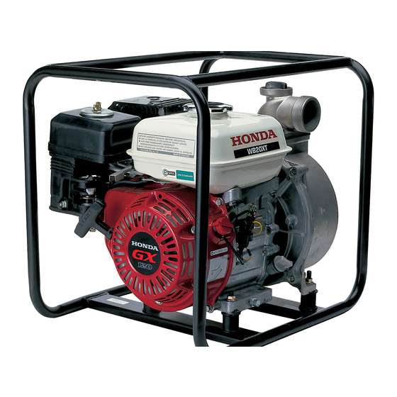
- Page 1 Owner ’s Manual PUMP WB20XT/WB30XT Click to Save As © 201 Honda Motor Co., Ltd.—All Rights Reserved...
- Page 2 The information and specifications included in this publication were in effect at the time of approval for printing. Honda Motor Co., Ltd. reserves the right, however, to discontinue or change specifications or design at any time without notice and without incurring any obligation whatever.
- Page 3 INTRODUCTION Congratulations on your selection of a Honda water pump. We are certain you will be pleased with your purchase of one of the finest water pumps on the market. We want to help you get the best results from your new water pump and to operate it safely.
- Page 4 INTRODUCTION A FEW WORDS ABOUT SAFETY Your safety and the safety of others are very important. And using this water pump safely is an important responsibility. To help you make informed decisions about safety, we have provided operating procedures and other information on labels and in this manual.
-
Page 5: Table Of Contents
CONTENTS PUMP SAFETY ................5 IMPORTANT SAFETY INFORMATION ........5 SAFETY LABEL LOCATIONS ............7 CONTROLS & FEATURES ..............8 COMPONENT & CONTROL LOCATIONS ........8 CONTROLS ................10 Fuel Valve Lever ..............10 Ignition Switch ...............10 Choke Lever ................11 Throttle Lever ................11 Recoil Starter Grip ..............12 FEATURES .................12 ®... - Page 6 Serial Number Location ............49 Carburetor Modification for High Altitude Operation ..50 Emission Control System Information ........51 Air Index .................53 Specifications ................54 CONSUMER INFORMATION ............58 DEALER LOCATOR INFORMATION .........58 Honda PUBLICATIONS .............58 Customer Service Information ..........59 QUICK REFERENCE INFORMATION ....Inside back cover...
-
Page 7: Pump Safety
PUMP SAFETY IMPORTANT SAFETY INFORMATION Honda WB20XT and WB30XT pumps are designed to pump only fresh water that is not intended for human consumption; other uses can result in injury to the operator or damage to the pump and other property. - Page 8 PUMP SAFETY Hot Exhaust The muffler becomes very hot during operation and remains hot for a while after stopping the engine. Be careful not to touch the muffler while it is hot. Let the engine cool before transporting the pump or storing it indoors.
-
Page 9: Safety Label Locations
These labels are considered permanent parts of your pump. If a label comes off or becomes hard to read, contact an authorized Honda servicing dealer for a replacement. [For American types] * French labels come with the water pump. -
Page 10: Controls & Features
CONTROLS & FEATURES COMPONENT & CONTROL LOCATIONS <WB20XT> THROTTLE LEVER DISCHARGE PORT FUEL FILLER CAP CHOKE LEVER FUEL VALVE LEVER OIL FILLER CAP/ DIPSTICK RECOIL STARTER GRIP IGNITION SWITCH STRAINER FRAME PRIMING WATER MUFFLER FILLER CAP AIR CLEANER SUCTION PORT... - Page 11 CONTROLS & FEATURES <WB30XT> THROTTLE LEVER DISCHARGE PORT CHOKE LEVER FUEL FILLER CAP FUEL VALVE LEVER OIL FILLER CAP/ DIPSTICK RECOIL STARTER GRIP IGNITION SWITCH STRAINER PRIMING WATER FRAME MUFFLER FILLER CAP AIR CLEANER SUCTION PORT PUMP DRAIN CAP OIL DRAIN PLUG...
-
Page 12: Controls
CONTROLS & FEATURES CONTROLS Fuel Valve Lever The fuel valve opens and closes FUEL VALVE LEVER the passage between the fuel tank and the carburetor. The fuel valve lever must be in the ON position for the engine to run. When the engine is not in use, leave the fuel valve lever in the OFF position to prevent... -
Page 13: Choke Lever
CONTROLS & FEATURES Choke Lever The choke lever opens and closes CHOKE LEVER the choke valve in the carburetor. The CLOSED position enriches the fuel mixture for starting a cold engine. OPEN The OPEN position provides the CLOSED correct fuel mixture for operation after starting, and for restarting a warm engine. -
Page 14: Recoil Starter Grip
CONTROLS & FEATURES Recoil Starter Grip Pulling the recoil starter grip operates the recoil starter to crank the engine. RECOIL STARTER GRIP FEATURES ® Oil Alert System ® The Oil Alert system is designed to prevent engine damage caused by an insufficient amount of oil in the crankcase. Before the oil level in the crankcase can fall below a safe limit, the Oil Alert system will automatically stop the engine (the ignition switch will remain in the ON position). -
Page 15: Before Operation
BEFORE OPERATION ARE YOU READY TO GET STARTED? Your safety is your responsibility. A little time spent in preparation will significantly reduce your risk of injury. Knowledge Read and understand this manual. Know what the controls do and how to operate them. Familiarize yourself with the pump and its operation before you begin pumping. -
Page 16: Is Your Pump Ready To Go
BEFORE OPERATION IS YOUR PUMP READY TO GO? For your safety, and to maximize the service life of your equipment, it is very important to take a few moments before you operate the pump to check its condition. Be sure to take care of any problem you find, or have your servicing dealer correct it, before you operate the pump. -
Page 17: Check The Suction And Discharge Hoses
BEFORE OPERATION Check the Suction and Discharge Hoses • Check the general condition of the hoses. Be sure the hoses are in serviceable condition before connecting them to the pump. Remember that the suction hose must be reinforced construction to prevent hose collapse. -
Page 18: Operation
OPERATION SAFE OPERATING PRECAUTIONS To safely realize the full potential of this pump, you need a complete understanding of its operation and a certain amount of practice with its controls. Before operating the pump for the first time, please review the IMPORTANT SAFETY INFORMATION on page 5 and the chapter titled BEFORE OPERATION. -
Page 19: Pump Placement
OPERATION PUMP PLACEMENT For best pump performance, place the pump on a firm, level surface, and near the water level, and use hoses that are no longer than necessary. That will enable the pump to produce the greatest output with the least self-priming time. As head (pumping height) increases, pump output decreases. -
Page 20: Suction Hose Installation
Do not use a hose smaller than the pump’s suction port size. Minimum hose size: WB20XT=2 in (50 mm) WB30XT=3 in (80 mm) The suction hose should be no longer than necessary. Pump performance is best when the pump is near the water level and the hoses are short. -
Page 21: Discharge Hose Installation
OPERATION DISCHARGE HOSE INSTALLATION Use a commercially available hose and hose connector with the hose clamp provided with the pump (if necessary). It is best to use a short, large-diameter hose, because that will reduce fluid friction and improve pump output. A long or small-diameter hose will increase fluid friction and reduce pump output. -
Page 22: Priming The Pump
OPERATION PRIMING THE PUMP Before starting the engine, remove the filler cap from the pump chamber. Fill the pump chamber to the undersurface of the discharge port with water. Reinstall the filler cap and tighten it securely. Operating the pump dry will destroy the pump seal. If the pump has been operated dry, stop the engine immediately, and allow the pump to cool before priming. -
Page 23: Starting The Engine
OPERATION STARTING THE ENGINE 1. Prime the pump (see page 20). 2. Move the fuel valve lever to the ON position. FUEL VALVE LEVER 3. To start a cold engine, move the choke lever to the CLOSED position. To restart a warm engine, leave the choke lever in the OPEN position. - Page 24 OPERATION 5. Turn the ignition switch to the ON position. IGNITION SWITCH 6. Pull the recoil starter grip lightly until you fill resistance, and then pull briskly. Do not allow the recoil starter grip to snap back against the engine. Return it gently to prevent damage to the starter.
-
Page 25: Setting Engine Speed
OPERATION 7. If the choke lever was moved to the CLOSED position to start the engine, gradually move it to the OPEN position as the engine warms up. CHOKE LEVER OPEN SETTING ENGINE SPEED After starting the engine, move the throttle lever to the FAST position for self-priming, and check pump output. -
Page 26: Stopping The Engine
OPERATION STOPPING THE ENGINE To stop the engine in an emergency, simply turn the ignition switch to the OFF position. Under normal conditions, use the following procedure. 1. Move the throttle lever to the SLOW position. THROTTLE LEVER SLOW 2. Turn the ignition switch to the OFF position. IGNITION SWITCH... - Page 27 OPERATION 3. Turn the fuel valve lever to the OFF position. FUEL VALVE LEVER After use, remove the pump drain plug (see page 41), and drain the pump chamber. Remove the filler cap, and flush the pump chamber with clean, fresh water. Allow the water to drain from the pump chamber, and then reinstall the filler cap and drain plug.
-
Page 28: Servicing Your Pump
Remember that your servicing dealer knows your pump best and is fully equipped to maintain and repair it. To ensure the best quality and reliability, use only new, Honda Genuine parts or their equivalents for repair and replacement. Maintenance, replacement, or repair of emission control devices and systems may be performed by any engine repair establishment or individual, using parts that are ‘‘certified’’... -
Page 29: Maintenance Safety
SERVICING YOUR PUMP MAINTENANCE SAFETY Some of the most important safety precautions follow. However, we cannot warn you of every conceivable hazard that can arise in performing maintenance. Only you can decide whether or not you should perform a given task. Failure to properly follow maintenance instructions and precautions can cause you to be seriously hurt or killed. -
Page 30: Maintenance Schedule
(1) Service more frequently when used in dusty areas. (2) These items should be serviced by your servicing dealer, unless you have the proper tools and are mechanically proficient. Refer to the Honda shop manual for service procedures. See ‘‘Honda Publications’’ on page 58 for ordering information. -
Page 31: Refueling
SERVICING YOUR PUMP REFUELING With the engine stopped and on a level surface, remove the fuel tank cap and check the fuel level. Refill the tank if the fuel level is low. Gasoline is highly flammable and explosive. You can be burned or seriously injured when handling fuel. -
Page 32: Fuel Recommendations
SERVICING YOUR PUMP Never refuel the engine inside a building where gasoline fumes may reach flames or sparks. Keep gasoline away from appliance pilot lights, barbecues, electric appliances, power tools, etc. Spilled fuel is not only a fire hazard, it causes environmental damage. Wipe up spills immediately. -
Page 33: Engine Oil Level Check
SERVICING YOUR PUMP ENGINE OIL LEVEL CHECK Check the engine oil level with the engine stopped and in a level position. 1. Remove the oil filler cap/dipstick and wipe it clean. 2. Insert and remove the dipstick without screwing it into the filler neck. -
Page 34: Engine Oil Change
3. With the engine in a level position, fill to the edge of the oil filler hole with the recommended oil (see page 33). Engine oil capacities WB20XT: 0.59 US qt (0.56 L) WB30XT: 0.61 US qt (0.58 L) Improper disposal of engine oil can be harmful to the environment. If you change your own oil, please dispose of used motor oil properly. -
Page 35: Engine Oil Recommendation
SERVICING YOUR PUMP ENGINE OIL RECOMMENDATION Oil is a major factor affecting performance and service life. Use 4-stroke automotive detergent oil. Use 4-stroke motor oil that meets or exceeds the requirements for API service category SJ or later (or equivalent). Always check the API service label on the oil container to be sure it includes the letters SJ or later (or equivalent). -
Page 36: Servicing Your Pump (Continued)
SERVICING YOUR PUMP AIR FILTER INSPECTION Unscrew the wing nut and remove the air cleaner cover. Check the air filter to be sure it is clean and in good condition. If the air filter is dirty, clean it as described on page 35. Replace the air filter if it is damaged. -
Page 37: Air Filter Cleaning
SERVICING YOUR PUMP AIR FILTER CLEANING A dirty air filter will restrict air flow to the carburetor, reducing engine performance. If you operate the pump in very dusty areas, clean the air filter more frequently than specified in the Maintenance Schedule (see page 28). -
Page 38: Sediment Cup Cleaning
SERVICING YOUR PUMP SEDIMENT CUP CLEANING 1. Move the fuel valve lever to the OFF position, then remove the fuel sediment cup and O-ring. Gasoline is highly flammable and explosive. You can be burned or seriously injured when handling fuel. •... -
Page 39: Spark Plug Service
SERVICING YOUR PUMP SPARK PLUG SERVICE In order to service the spark plug, you will need a spark plug wrench (commercially available). Recommended spark plug: BPR6ES (NGK) Incorrect spark plugs can cause engine damage. For good performance, the spark plug must be properly gapped and free of deposits. - Page 40 SERVICING YOUR PUMP 5. Install the spark plug carefully, by hand, to avoid cross-threading. 6. After the spark plug seats, tighten with a 13/16-inch spark plug wrench to compress the washer. If reinstalling the used spark plug, tighten 1/8—1/4 turn after the spark plug seats.
-
Page 41: Spark Arrester Service (Optional Equipment)
Check local laws and regulations. A spark arrester is available from authorized Honda servicing dealers. The spark arrester must be serviced every 100 hours to keep it functioning as designed. -
Page 42: Storage
STORAGE STORAGE PREPARATION Proper storage preparation is essential for keeping your pump trouble-free and looking good. The following steps will help to keep rust and corrosion from impairing your pump’s function and appearance, and will make the engine easier to start when you use the pump again. -
Page 43: Fuel
STORAGE 4. Stop the engine, and allow it to cool. 5. Remove the pump drain plug, and flush the pump with clean, fresh water. Allow the water to drain from the pump chamber, and then reinstall the drain plug. 6. After the pump is clean and dry, touch up any damaged paint, and coat areas that may rust with a light film of oil. - Page 44 STORAGE Adding a Fuel Stabilizer to Extend Fuel Storage Life Short Term Storage (30—90 days) If your equipment will not be used for 30—90 days, we recommend the following to prevent fuel-related problems: 1. Add fuel stabilizer following the manufacturer’s instructions. When adding a fuel stabilizer, fill the fuel tank with fresh gasoline.
- Page 45 STORAGE Long Term or Seasonal Storage (greater than 90 days) Draining the Fuel Tank and Carburetor 1. Place an approved gasoline container below the carburetor, and use a funnel to avoid spilling fuel. 2. Move the fuel valve lever to the OFF position, loosen the carburetor drain bolt by turning 1 to 2 turns counter clockwise and drain the fuel in the carburetor.
-
Page 46: Engine Oil
STORAGE 4. After all fuel has drained into the container, tighten the carburetor drain bolt securely. 5. Reinstall a new O-ring and sediment cup. 6. Move the fuel valve lever to the OFF position. Engine Oil Change the engine oil (see page 32). Engine Cylinder 1. -
Page 47: Storage Precautions
STORAGE STORAGE PRECAUTIONS If your pump will be stored with gasoline in the fuel tank and carburetor, it is important to reduce the hazard of gasoline vapor ignition. Select a well-ventilated storage area away from any appliance that operates with a flame, such as a furnace, water heater, or clothes dryer. -
Page 48: Transporting
TRANSPORTING If the pump has been running, allow the engine to cool for at least 15 minutes before loading the pump on the transport vehicle. A hot engine and exhaust system can burn you and can ignite some materials. Keep the pump level when transporting to reduce the possibility of fuel leakage. -
Page 49: Taking Care Of Unexpected Problems
Dry and reinstall spark plug. Start engine engine). with throttle lever in FAST position. Fuel filter clogged, carburetor Take engine to an authorized Honda malfunction, ignition malfunction, valves servicing dealer, or refer to shop manual. stuck, etc. Engine Lacks Power... -
Page 50: Pump
TAKING CARE OF UNEXPECTED PROBLEMS PUMP No Pump Output Possible Cause Correction Pump is placed on inappropriate places. Place the pump on a firm, level surface. Pump not primed. Prime pump (p. 20) Hose collapsed, cut or punctured. Replace suction hose (p. 18). Strainer not completely underwater. -
Page 51: Technical Information
TECHNICAL INFORMATION Serial Number Location <WB20XT> <WB30XT> ENGINE SERIAL NUMBER FRAME SERIAL NUMBER Record the frame serial number (if assigned) and the engine serial number in the space below. You will need these serial numbers when ordering parts, and when making technical or warranty inquiries (see page 59). -
Page 52: Carburetor Modification For High Altitude Operation
TECHNICAL INFORMATION Carburetor Modification for High Altitude Operation At high altitude, the standard carburetor air-fuel mixture will be too rich. Performance will decrease, and fuel consumption will increase. A very rich mixture will also foul the spark plug and cause hard starting. Operation at an altitude that differs from that at which this engine was certified, for extended periods of time, may increase emissions. -
Page 53: Emission Control System Information
The following instructions and procedures must be followed in order to keep the Honda engine emissions within the emission standards. Tampering and Altering Tampering is a violation of Federal and California law. - Page 54 • Black exhaust smoke or high fuel consumption. Replacement Parts The emission control systems on your new Honda engine were designed, built, and certified to conform with U.S. EPA, California and Canadian emission regulations. We recommend the use of Honda Genuine parts whenever you have maintenance done.
-
Page 55: Air Index
TECHNICAL INFORMATION Air Index An Air Index Information hang tag/label is applied to engines certified to an emission durability time period in accordance with the requirements of the California Air Resources Board. The bar graph is intended to provide you, our customer, the ability to compare the emissions performance of available engines. -
Page 56: Specifications
TECHNICAL INFORMATION Specifications WB20XT Dimensions and weight Length 19.3 in (490 mm) Width 14.4 in (365 mm) Height 16.7 in (420 mm) Dry mass [weight] 44 lbs (20 kg) Engine design and performance Model GX120 Engine type 4-stroke, overhead valve, single cylinder Displacement 7.2 cu-in (118 cm... - Page 57 TECHNICAL INFORMATION WB20XT (continued) Pump Suction port diameter 2.0 in (50 mm) Discharge port diameter 2.0 in (50 mm) Total head 105.6 ft (32 m) Suction head 24.6 ft (7.5 m) Discharge capacity 163.8 US gal (620 L) per minute Self-priming time 110 seconds at 16.4 ft (5 m)
- Page 58 TECHNICAL INFORMATION WB30XT Dimensions and weight Length 20.1 in (510 mm) Width 15.2 in (385 mm) Height 17.9 in (455 mm) Dry mass [weight] 57 lbs (26 kg) Engine design and performance Model GX160 Engine type 4-stroke, overhead valve, single cylinder Displacement 9.9 cu-in (163 cm [bore×stroke]...
- Page 59 TECHNICAL INFORMATION WB30XT (continued) Pump Suction port diameter 3.1 in (80 mm) Discharge port diameter 3.1 in (80 mm) Total head 75.9 ft (23 m) Suction head 24.6 ft (7.5 m) Discharge capacity 290.6 US gal (1,100 L) per minute Self-priming time 150 seconds at 16.4 ft (5 m)
-
Page 60: Consumer Information
CONSUMER INFORMATION DEALER LOCATOR INFORMATION To find an authorized Honda Servicing Dealer anywhere in the United States: Visit our web site: http://powerequipment.honda.com/dealer-locator To find an authorized Honda Servicing Dealer anywhere in Canada: Call 1-888-946-6329 or visit our website: www.honda.ca Honda PUBLICATIONS (For USA) Shop Manual This manual covers complete maintenance and overhaul procedures. -
Page 61: Customer Service Information
CONSUMER INFORMATION Customer Service Information Honda Power Equipment dealership personnel are trained professionals. They should be able to answer any question you may have. If you encounter a problem that your dealer does not solve to your satisfaction, please discuss it with the dealership’s management. -
Page 62: Quick Reference Information
Unleaded gasoline with a pump octane rating of 86 or higher (page 30) Engine Oil Type SAE 10W-30, API SJ, for general use (page 33) Capacity WB20XT: 0.59 US qt (0.56 L) WB30XT: 0.61 US qt (0.58 L) Spark Plug Type NGK: BPR6ES 0.028—0.031 in (0.70—0.80 mm) - Page 63 00X31YG...
Need help?
Do you have a question about the WB20XT and is the answer not in the manual?
Questions and answers