Table of Contents
Advertisement
Ratings
.................................................... 60,000 to 180,000
Input:
Fuels:
.........................................Natural gas or propane gas
Max. supply pressure .............................14
Min. supply pressure ................................5
Manifold pressure .................................3.5
Electrical: Power ...................................120
Motor.................................................. 1/50
Ignition:
.................................. Norton hot surface ignitor, 120
Control:
.................................Honeywell S89C primary control
Agencies: ........................................................ CSA certified, U. S.
The G3B burner has been assigned
U. S. Patent No. 4397631
Instruction Manual
Contents
PLEASE read this first.......................................................... 2
Codes and standards........................................................... 2
G3B Gas burner at-a-glance .............................................. 3
Prepare site • prepare burner • mount burner ................ 4
Install gas piping .................................................................. 9
Wire burner ......................................................................... 10
Check system • start-up burner/appliance .................... 12
Maintenance and service procedures ........................... 17
Troubleshooting .................................................................. 19
Dimensions and mounting information .......................... 21
Replacement parts............................................................. 22
btuh
.
.
inches w
c
.
.
inches w
c
.
.
inches w
c
/60
/1-
, 8
v
hz
phase
amps
, 3450
hp
rpm
v
©
Carlin Combustion Technology, Inc.
126 Bailey Road
Ph 203-680-9401
T
ech support
Installer/servicer - Except where specifi-
cally stated otherwise, this manual must be used only by
a qualified service technician. In the state of MA, this
product must be installed by a licensed plumber or gas
fitter. Failure to comply with this or other requirements
in this manual could result in severe personal injury, death
or substantial property damage.
Handling - Handle burner (and hot surface ignitor)
carefully to avoid cracking or breaking the ceramic ignitor.
Ignitor protrudes slightly beyond burner head. Do not set
burner on its end.
User - Refer only to User's Information manual
for information regarding operation of this burner. The
remainder of this manual is intended only for your
service technician. The burner and heat exchanger must
be inspected and started at least annually by your service
technician.
Copyright 2015 - Carlin Combustion Technology, Inc.
800-989-2275
North Haven, CT 06473
Fx 203-680-9403
carlincombustion.com
Advertisement
Table of Contents

Related Manuals for Carlin G3B


Summary of Contents for Carlin G3B
-
Page 1: Table Of Contents
Instruction Manual Contents PLEASE read this first............2 Codes and standards............2 G3B Gas burner at-a-glance ..........3 Prepare site • prepare burner • mount burner ....4 Install gas piping ..............9 Wire burner ................. 10 Check system • start-up burner/appliance ....12 Perform checkout procedure •... -
Page 2: Please Read This First
• “Installation of Domestic Gas Conversion Burners,” ANSI Z21.8. • National Fuel Gas Code, ANSI Z223.1/NFPA 54. Carlin G3B gas burners are CSA certified for use with natural gas or propane gas, United States installations only. • National Electrical Code, ANSI/NFPA 70. -
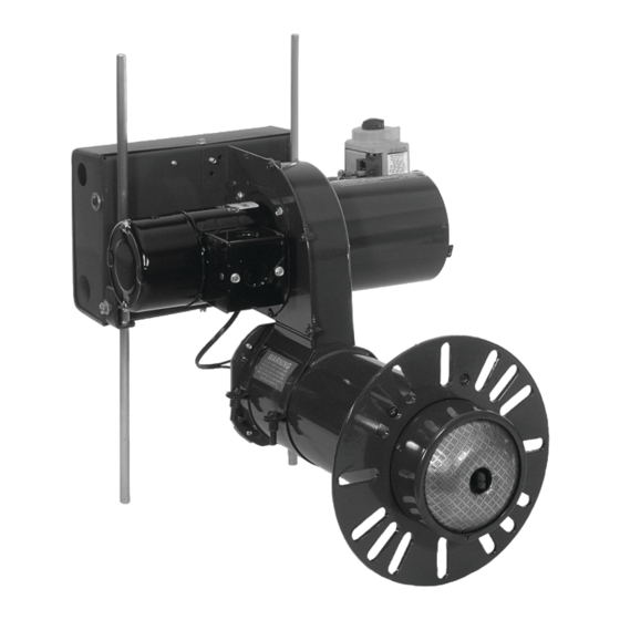
Page 3: G3B Gas Burner At-A-Glance
Model G3B Gas burner — Instruction manual G3B Gas Burner At-a-Glance Air tube, with powder coat paint finish 12 Primary control (Honeywell Model S89C primary control, for use with flame rectification) Flameholder 13 Control transformer, 120 / 24 , 40... -
Page 4: Prepare Site • Prepare Burner • Mount Burner
Model G3B Gas burner — Instruction manual 1. Prepare Site • Prepare Burner • Mount Burner Inspect installation site Figure 1 Vent and vent connector installation Inspect, repair and/or replace vent system Do not install this burner unless you have verified the entire vent system and the appliance are in good condition and comply with all applicable codes. -
Page 5: Min. Supply Pressure
Model G3B Gas burner — Instruction manual 1. Prepare Site • Prepare Burner • Mount Burner (continued) Figure 2 Locating & sizing air openings Inspect installation site Combustion/ventilation air openings Installing the burner/appliance in a space that does not provide enough air for combustion and ventilation can result in severe personal injury, death or substantial property damage. - Page 6 Model G3B Gas burner — Instruction manual 1. Prepare Site • Prepare Burner • Mount Burner (continued) Prepare the appliance Figure 3 Minimum combustion chamber dimensions Burner input: Install a gas burner sized for the normal input rating of the appliance. Do not install a burner with a higher firing rate than the appliance rating.
- Page 7 The universal flange supplied with G3B Gas burners is http://www.cdc.gov/niosh/homepage.html. intended only for firing chambers with negative overfire pressure. The G3B burner must not be installed on a Ceramic fiber removal:To prevent airborne dust, thor- product that operates with a pressurized combustion oughly wet ceramic fiber with water before handling.
- Page 8 Figure 4. The orifice is shipped with a pilot hole only. Firing the burner with the orifice as shipped can result in damage to the burner. Never fire the G3B burner below 60,000 Btuh input. The flameholder can overheat, resulting in potential severe personal injury, death or substantial property damage.
-
Page 9: Install Gas Piping
Model G3B Gas burner — Instruction manual 2. Install Gas Piping from Meter to Combination Gas Valve Code compliance Gas supply pressure — natural or propane The burner/appliance installation must comply with codes listed on page 2 and • Maximum supply pressure: 14 inches w.c. -
Page 10: Wire Burner
Model G3B Gas burner — Instruction manual 3. Wire Burner Code compliance Electrically ground burner — The burner must be grounded in accordance with local codes or, in the absence of local The burner/appliance installation must comply with codes listed on page codes, with the National Electrical Code, ANSI/NFPA 70 (in 2 and any other locally applicable codes. - Page 11 Model G3B Gas burner — Instruction manual 3. Wire Burner (continued) Verify power supply 2. The 120 power connections to the burner must be connected as shown in Figure 7. The control is polarity-sensitive, and will not work if 1. The burner requires a 120 /single-phase power supply.
-
Page 12: Check System • Start-Up Burner/Appliance
Model G3B Gas burner — Instruction manual 4. Check System • Start-up Burner/Appliance Inspect/check system Figure 8 Air throttle adjustment Before starting the burner and appliance, verify the system has been installed as directed by this manual and the appliance instructions. - Page 13 Flame failure If the primary control loses flame signal during a run period, it deactivates the gas valve within 2 seconds. The control Ignition The G3B burner uses a silicon carbide hot surface ignitor restarts the heating cycle, beginning with a 34-second for ignition. The Honeywell S89C primary control feeds 120...
-
Page 14: Max. Supply Pressure
Model G3B Gas burner — Instruction manual 5. Perform Checkout Procedures • Fill Out Certificate Make final burner adjustments Make final burner adjustments (continued) Check for leaks in gas piping Check/adjust gas valve outlet pressure ❏ ❏ Smell around burner to make sure there is no gas leak in near-burner With burner running, check manometer reading for combination gas piping. - Page 15 Model G3B Gas burner — Instruction manual 5. Perform Checkout Procedures • Fill Out Certificate (continued) Make final burner adjustments Make final burner adjustments (continued) (continued) Check combustion using instruments Check flame signal You must use combustion test instruments. Failure to properly Electrical shock hazard —...
- Page 16 Model G3B Gas burner — Instruction manual 5. Perform Checkout Procedures • Fill Out Certificate (continued) Verify burner/appliance operation Prepare burner for normal operation ❏ Cycle burner off with appliance controls. Then turn off power to the Check burner/appliance/controls operation appliance.
-
Page 17: Maintenance And Service Procedures
Model G3B Gas burner — Instruction manual 6. Maintenance and Service Procedures Annual start-up & service Annual start-up & service (continued) This burner should be started and serviced at least annually 7. Swing the hold-on bracket away and carefully pull out the ignition tube by a qualified service technician. - Page 18 Model G3B Gas burner — Instruction manual 6. Maintenance and Service Procedures (continued) Maintenance/service procedures Maintenance/service procedures (continued) Cleaning blower wheel Replacing blower motor or wheel ❏ Periodically inspect and clean the blower housing and wheel. Follow this procedure to replace motor or wheel.
-
Page 19: Troubleshooting
Model G3B Gas burner — Instruction manual 7. Troubleshooting Problem Possible Corrective action cause These procedures must only be performed by a qualified service technician. Use care when performing tests on electrically or mechanically live parts. Disconnect power to burner/appliance and close WARNING main manual gas valve when removing components for service. - Page 20 Model G3B Gas burner — Instruction manual 7. Troubleshooting (continued) Problem Possible Corrective action cause These procedures must only be performed by a qualified service technician. Use care when performing tests on electrically or mechanically live parts. Disconnect power to burner/appliance and close WARNING main manual gas valve when removing components for service.
-
Page 21: Dimensions And Mounting Information
The universal flange supplied with G3B Gas burners is intended only for firing chambers with negative overfire pressure. The G3B burner must not be installed on a product that operates with a pressurized combustion chamber. Failure to comply could result in severe personal injury, death or substantial property damage. -
Page 22: Replacement Parts
Air Inlet Tube Assembly 50823 Air Throttle 50757 G3B Orifice, No. 33 drill (.113 dia.), Propane 60,000 BTUH, drill open for other rates 60582 Orifice Nipple 61663 Gas Valve, dual, 24-volt (1/2” X 1/2” LH-outlet) 41053 Gasket, mounting flange... - Page 23 Model G3B Gas burner — Instruction manual 9. Replacement parts (continued) MNG3B Gas 041015...
- Page 24 Model G3B Gas burner — Instruction manual MNG3B Gas 041015...
Need help?
Do you have a question about the G3B and is the answer not in the manual?
Questions and answers