Table of Contents
Advertisement
Quick Links
Instructions
Parts
MODEL 510
Airless Spray Gun
7400 psi (50.8 MPa, 510 bar) Maximum Working Pressure
Part No. 236995, Series B
Includes a Heavy-Duty 510 RAC IV Tip Guard and size 619 SwitchTip.
Read warnings and instructions.
See page 2 for Table of Contents.
GRACO INC. P.O. BOX 1441 MINNEAPOLIS, MN 55440-1441
Copyright 1994, Graco Inc. is registered to I.S. EN ISO 9001
308438F
03965
II 2 G
Advertisement
Table of Contents

Related Manuals for Graco 510


Summary of Contents for Graco 510
- Page 1 Airless Spray Gun 308438F 7400 psi (50.8 MPa, 510 bar) Maximum Working Pressure Part No. 236995, Series B Includes a Heavy-Duty 510 RAC IV Tip Guard and size 619 SwitchTip. Read warnings and instructions. See page 2 for Table of Contents. 03965 GRACO INC.
-
Page 2: Table Of Contents
................Graco Standard Warranty . -
Page 3: Warnings
WARNING INJECTION HAZARD Spray from the gun, hose leaks or ruptured components can inject fluid into your body and cause an extremely serious injury, including the need for amputation. Splashing fluid in the eyes or on the skin can also cause serious injury. D Fluid injected into the skin might look like just a cut, but it is a serious injury. - Page 4 D This equipment is for professional use only. D Read all instruction manuals, tags, and labels before operating the equipment. D Use the equipment only for its intended purpose. If you are uncertain about usage, call your Graco distributor. D Do not alter or modify this equipment. Use only genuine Graco parts and accessories.
- Page 5 Notes 308438...
-
Page 6: Installation/Operation
Additional cards are available at no charge located in the spray area. Also read FIRE OR from Graco Inc. EXPLOSION HAZARD on page 4. Check your local electrical code for detailed grounding WARNING instructions for your area and type of equipment. -
Page 7: Pressure Relief Procedure
Installation/Operation Pressure Relief Procedure 1. Lock the gun trigger safety. 2. Shut off the power to the pump. Open the bleed- type master air valve (pneumatic pumps only). WARNING 3. Unlock the gun trigger safety. INJECTION HAZARD 4. Hold a metal part of the gun firmly to a grounded The system pressure must be manually metal pail. -
Page 8: How To Operate The Gun
Installation/Operation How to Operate the Gun 4. Install the SwitchTip (8) and tip guard (30). Follow the instructions in the manual, supplied. See Fig. 2. WARNING 5. Start the pump. Trigger the gun onto test paper. Adjust the fluid pressure until the spray is RECOIL HAZARD completely atomized. -
Page 9: Care Of The Spray Tip And Tip Guard
Installation/Operation Care of the Spray Tip and Tip Guard If the spray tip clogs while spraying 1. Stop spraying immediately. 2. Lock the gun trigger safety. Rotate the RAC IV tip WARNING handle back 180 . See Fig. 4. INJECTION HAZARD 3. -
Page 10: How To Flush The Gun
Installation/Operation How to Flush the Gun Flush the pump and gun before the fluid can dry in it. If it is available, the flushing procedure provided in your pump or sprayer manual should be used instead of this WARNING procedure. To reduce the risk of serious injury, including splashing fluid in the eyes or on the skin, or static electric discharge when flushing:... -
Page 11: How To Check The Gun Diffuser Operation
Installation/Operation How to Check the Gun Diffuser Operation Check the diffuser operation weekly. The gun diffuser/ seat (2a) breaks up spray and reduces the risk of The Standard Needle and Seat Kit, 237398, has the injection when the tip is not installed. Perform the test number 090 stamped on the needle and seat. -
Page 12: Service
Service WARNING INJECTION HAZARD To reduce the risk of an injection injury, follow the Pressure Relief Procedure on page 7 before checking or servicing the gun and whenever you are instructed to relieve the pressure. Repair Notes 03969 Fig. 7 The needle and seat are available only as a kit which 3. - Page 13 Service Fig. 12 03974 8. Remove the needle (2c). Unscrew the seal retainer (2d). Remove the seal (2e). See Fig. 12. 03972 Fig. 10 Cleaning Clean all parts and cavities thoroughly with a compat- ible solvent. Dry with a rag or compressed air. Replace any parts that are worn or damage.
- Page 14 Service Grease this side 03676 03979 Fig. 14 Fig. 17 2. Lightly grease the small end of the needle (2c) and 5. If the spring (19) was removed, grease the spring then guide it into the large end of the fluid housing adjuster (20) and place it on the spring.
- Page 15 Service Turn in until screw stops Fig. 21 03980 Fig. 19 03971 9. If it was removed, install the spring tension screw (21) at the rear of the gun. Then, turn the screw in until it stops. See Fig. 21. 7.
-
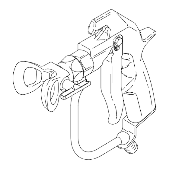
Page 16: Parts
Parts Part No. 236995, Series B Model 510 Airless Spray Gun 03964 Ref. Ref. Part No. Description Qty. Part No. Description Qty. 237502 GUN BODY 112410 E-CLIP 237398 NEEDLE AND SEAT KIT 187965 PIVOT PIN includes items 2a–2e (parts not... -
Page 17: Technical Data
............. 7400 psi (50.8 MPa, 510 bar) Fluid orifice size . -
Page 18: Graco Standard Warranty
With the exception of any special, extended, or limited warranty published by Graco, Graco will, for a period of twelve months from the date of sale, repair or replace any part of the equipment determined by Graco to be defective.
Need help?
Do you have a question about the 510 and is the answer not in the manual?
Questions and answers