Advertisement
Table of Contents
INSTRUCTIONS–PARTS LIST
This manual contains important
warnings and information.
READ AND KEEP FOR REFERENCE.
INSTRUCTIONS
Kits, Line Guide
For LineLazert 3500 & 5000 and LineLazer II 3900 & 5900
Model 241101, Series A
Short, for parking lot striping and road striping
Model 241102, Series A
Long, for road striping only
Installation
NOTE: Steps 1 and 2 apply to
LineLazer 3500 & 5000 only.
1. Drill two holes on both sides of chassis frame,
as shown in Fig. 1.
4X
.330
through both walls
1.0 in.
A = 6.55 in. — LineLazer 3500 & 5000 (must be drilled)
A = 5.55 in. — LineLazer 3900 & 5900 (already drilled)
Fig. 1
GRACO INC. P.O. BOX 1441 MINNEAPOLIS, MN 55440–1441
1.0 in.
Front
A
8851A
ECOPYRIGHT 1999, GRACO INC.
Graco Inc. is registered to I.S. EN ISO 9001
First choice when
quality counts.t
2. Mount one bracket (6) on right side of chassis
(viewed from front) with two flange screws (7) and
two lock nuts (8), as shown in Fig. 2.
6
8
7
Fig. 2
NOTE: Steps 3 and 4 apply to all LineLazers.
3. Slide left-side bracket (6) onto rod (1). Note
bracket orientation. Insert rod in right-side bracket.
4. Mount left-side bracket (6) on chassis with two
flange screws (7) and two lock nuts (8).
308941
Rev. B
6, 7, 8
Right-side bracket is
already mounted on
LineLazer 3900 & 5900.
1
8850A
Advertisement
Table of Contents

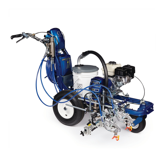
Summary of Contents for Graco LineLazer 3500
- Page 1 Fig. 2 NOTE: Steps 3 and 4 apply to all LineLazers. A = 6.55 in. — LineLazer 3500 & 5000 (must be drilled) A = 5.55 in. — LineLazer 3900 & 5900 (already drilled) 3. Slide left-side bracket (6) onto rod (1). Note bracket orientation.
- Page 2 8850A Graco Phone Number TO PLACE AN ORDER, contact your Graco distributor, or call this number to identify the distributor closest to you: 1–800–690–2894 Toll Free. All written and visual data contained in this document reflect the latest product information available at the time of publication.


Need help?
Do you have a question about the LineLazer 3500 and is the answer not in the manual?
Questions and answers