Table of Contents
Advertisement
Quick Links
Advertisement
Table of Contents

Related Manuals for Unical ENERPUMP DHW 72


Summary of Contents for Unical ENERPUMP DHW 72
- Page 1 Luxury Air Source Heat Pump Monobloc system - Installation and Service Manual - Heating/Cooling/Domestic Hot Water Heating/Cooling ENERPUMP DHW 72 ENERPUMP RK 72 ENERPUMP DHW 97 ENERPUMP RK 97 ENERPUMP DHW 110 ENERPUMP RK 110 ENERPUMP DHW 143 ENERPUMP RK 143...
-
Page 2: Table Of Contents
OVERVIEW OF THE UNIT ………………………………………………………………………………..………………….…….. External view: ENERPUMP DHW 72 (97) and ENERPUMP RK 72 (97) ……………………………………………. 13 Internal view: ENERPUMP DHW 72 (97) and ENERPUMP RK 72 (97).……………………………………………. 14 External view: ENERPUMP DHW 110 and ENERPUMP RK 110……………………………………………………….. 15 Internal view: ENERPUMP DHW 110 and ENERPUMP RK 110……………………………………………………….. - Page 3 Piping insulation …………………………………………………………………………………………………………………………….. 33 Field wiring …………………………………………………………………………………………………………………………………….. 34 SYSTEM SET-UP ………………………………………………………………………………………………………………. 35 DIP Switch Setting …………………………………………………………………………………………………………………………. 35 Pre-operation Checks ……………………………………………………………………………………………………………………. 38 Checks before initial start-up …………………………………………………………………………………………………. 38 Setting the pump speed …………………………………………………………………………………………………………. 39 MAINTENANCE …………………………………………………………………………………………………..…………… 40 TROUBLESHOOTING …………………………………………………………………………………………………………………. General guidelines ………………………………………………………………………………………………………………………… 41 General symptoms …………………………………………………………………………………………………………………………...
-
Page 4: Introduction
INTRODUCTION This manual This manual includes the necessary information about the unit. Please read this manual carefully before you use and maintain the unit. General information The luxury air source heat pump monobloc system consists out of only the outdoor unit in which all hydraulic parts are located. -
Page 5: Items Inside Product Box
Thank you for choosing the luxury air source heat pump- Monobloc system. Before starting installation, please make sure that all parts are found inside the product box. The Unit Box Item Image Quantity ENERPUMP DHW 72 ENERPUMP RK 72 ENERPUMP DHW 97 ENERPUMP RK 97 ENERPUMP DHW 110 ENERPUMP RK 110... - Page 6 Cycle diagram As the luxury air source monobloc unit is an air to water heat pump, there are two different fluids cycling inside the system, one is refrigerant and the other is water. The whole cycle diagram is shown below. Heating/Cooling/Domestic Hot Water version: Luxury Air Source Heat Pump-Monobloc System...
-
Page 7: Cycle Diagram: Enerpump Dhw 72 (97)(110)
Model: ENERPUMP DHW 72 , ENERPUMP DHW 97 and ENERPUMP DHW 110 Luxury Air Source Heat Pump-Monobloc System... -
Page 8: Cycle Diagram: Enerpump Dhw 143 (173)
Model: ENERPUMP DHW 143 and ENERPUMP DHW 173 Luxury Air Source Heat Pump-Monobloc System... -
Page 9: Cycle Diagram: Enerpump Rk 72 (97)(110)
Heating/Cooling version: Model: ENERPUMP RK 72 , ENERPUMP RK 97 and ENERPUMP RK 110 Luxury Air Source Heat Pump-Monobloc System... -
Page 10: Cycle Diagram: Enerpump Rk 143 (173)
Model: ENERPUMP RK 143 and ENERPUMP RK 173 Luxury Air Source Heat Pump-Monobloc System... -
Page 11: Safety Precautions
SAFETY PRECAUTIONS To prevent injury to the user, other people, or property damage, the following instructions must be followed. Incorrect operation due to ignoring of instructions may cause harm or damage. Install the unit only when it complies with local regulations, by-laws and standards. Check the main voltage and frequency. -
Page 12: Caution
Never use an extension cable to connect the unit to the electric power supply. If there is no suitable, earthed wall socket available, have one installed by a recognized electrician. Do not move/repair the unit yourself. Improper movement or repair on the unit could lead to water leakage, electrical shock, injury or fire. Have any repairs and/or maintenance only carried out by a recognized service engineer. - Page 13 Do not continue to run the unit when there is something wrong or there is a strange smell. The power supply needs to be shut ‘off’ to stop the unit; otherwise this may cause an electrical shock or fire. Be cautious when unpacking and installing the product. Sharp edges could cause injury.
-
Page 14: Overview Of The Unit
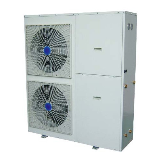
OVERVIEW OF THE UNIT External view: ENERPUMP DHW 72, ENERPUMP RK 72 ENERPUMP DHW 97, ENERPUMP RK 97 Luxury Air Source Heat Pump-Monobloc System... -
Page 15: Internal View: Enerpump Dhw 72 (97) And Enerpump Rk 72 (97)
Internal view: ENERPUMP DHW 72, ENERPUMP RK 72 ENERPUMP DHW 97, ENERPUMP RK 97 Description Description Left front plate Switch box Air outlet grill Water pump (RS15/6) Fan motor Four-way valve assembly Water flow switch Plate heat exchanger Three-way valve (only for DHW version) -
Page 16: External View: Enerpump Dhw 110 And Enerpump Rk 110
External view: ENERPUMP DHW 110, ENERPUMP RK 110 Luxury Air Source Heat Pump-Monobloc System... -
Page 17: Internal View: Enerpump Dhw 110 And Enerpump Rk 110
Internal view: ENERPUMP DHW 110, ENERPUMP RK 110 Description Description Left front plate Manometer (refrigerant pressure) Air outlet grill 1 Manometer (water pressure) Fan motor 1 Water pump (RS25/8) Fan 1 Four-way valve assembly Air outlet grill 2 Water flow switch Fan motor 2 Three-way valve (only for DHW version) Fan 2... -
Page 18: External View: Enerpump Dhw 143 (173) And Enerpump Rk 143 (173)
External view: ENERPUMP DHW 143, ENERPUMP RK 143 ENERPUMP DHW 173, ENERPUMP RK 173 Luxury Air Source Heat Pump-Monobloc System... -
Page 19: Internal View: Enerpump Dhw 143 (173) And Enerpump Rk 143 (173)
Internal view: ENERPUMP DHW 143, ENERPUMP RK 143 ENERPUMP DHW 173, ENERPUMP RK 173 Description Description Left front plate Backup heater vessel (20L) Air outlet grill 1 Switch box Fan motor 1 Water pump (RS25/8) Fan 1 Four-way valve assembly Air outlet grill 2 Water flow switch Fan motor 2... -
Page 20: Control Parts
CONTROL PARTS Control Panel Description Description OPERATION LED TEMPERATURE ADJUST BUTTON COOLING/HEATING ‘ON’/’OFF’ BUTTON DOMESTIC HOT WATER TEMPERATURE ADJUST BUTTON (only for DHW version) TIMER/ PROGRAMMING BUTTON DOMESTIC HOT WATER TEMPERATURE ADJUST BUTTON (only for DHW version) HOUR ADJUST BUTTON SPACE HEATING/COOLING BUTTON DAY OF THE WEEK ADJUST BUTTON DOMESTIC WATER HEATING BUTTON (only for... -
Page 21: Wiring Diagram: Enerpump Dhw 72 (97)
WIRING DIRGRAM Model: ENERPUMP DHW 72 and ENERPUMP DHW 97 Refer to the attached wiring diagram in the unit) Luxury Air Source Heat Pump-Monobloc System... -
Page 22: Wiring Diagram: Enerpump Dhw 110
Model: ENERPUMP DHW 110 ( Refer to the attached wiring diagram in the unit) Luxury Air Source Heat Pump-Monobloc System... -
Page 23: Wiring Diagram: Enerpump Dhw 143 (173)
Model: ENERPUMP DHW 143 and ENERPUMP DHW 173 Refer to the attached wiring diagram in the unit) Luxury Air Source Heat Pump-Monobloc System... -
Page 24: Remarks For Enerpump Dhw Version
Remarks for heating/cooling/domestic hot water version: -- For Two- way valve (B1 and B2) This function is reserved for two-way valve control. If an external two-way valve needs to be controlled by the heat pump system, you can use these ports according to their output signal. During space cooling mode, the ports (B1 and B2) will provide power 220-240V~ for use. -
Page 25: Wiring Diagram: Enerpump Rk 72 (97)
Model: ENERPUMP RK 72 and ENERPUMP RK 97 Refer to the attached wiring diagram in the unit) Luxury Air Source Heat Pump-Monobloc System... -
Page 26: Wiring Diagram: Enerpump Rk 110
Model: ENERPUMP RK 110 ( Refer to the attached wiring diagram in the unit) Luxury Air Source Heat Pump-Monobloc System... -
Page 27: Wiring Diagram: Enerpump Rk 143 (173)
Model: ENERPUMP RK 143 and ENERPUMP RK 173 Refer to the attached wiring diagram in the unit) Luxury Air Source Heat Pump-Monobloc System... -
Page 28: Remarks For Enerpump Rk Version
Remarks for heating/cooling version: -- For Two- way valve (B1 and B2) This function is reserved for two-way valve control. If an external two-way valve needs to be controlled by the heat pump system, you can use these ports according to their output signal. During space cooling mode, the ports (B1 and B2) will provide power 220-240V~ for use. -
Page 29: Installation Of The Unit
INSTALLATION OF THE UNIT Installation guidelines Precautions for selecting the location MAKE SURE TO PROVIDE FOR ADEQUATE MEASURES IN ORDER TO PREVENT THAT THE OUTDOOR UNIT WILL BE USED AS A SHELTER FOR SMALL ANIMALS. SMALL ANIMALS MAKING CONTACT WITH ELECTRICAL PARTS CAN CAUSE MALFUNCTIONS, SMOKE OR FIRE. -
Page 30: Installation Space
Installation space Mounting the unit When installing the outdoor unit, please refer to “Installation guidelines” to select an appropriate location. 1. Check the strength and level of the installation ground so that the unit will not cause any operating vibration or noise after installation. 2. -
Page 31: Water Pipe Work
Water pipe-work Checking the water circuit The 3-way valve is built-in the unit. So the unit is equipped with the water inlet/outlet for hot water connection, and the water inlet/outlet for space heating/cooling. The water circuits must be provided by a licensed technician and must comply with all relevant European and national regulations. -
Page 32: Checking The Water Volume And Expansion Vessel Pre-Pressure
Checking the water volume and expansion vessel pre-pressure The unit is equipped with an expansion vessel of 10 liters which has a default pre-pressure of 1 bar. To assure proper operation of the unit, the pre-pressure of the expansion vessel might need to be adjusted and the minimum and maximum water volume must be checked. -
Page 33: Setting The Pre-Pressure Of The Expansion Vessel
Setting the pre-pressure of the expansion vessel When it is required to change the default pre-pressure of the expansion vessel (1 bar), keep in mind the following guidelines: Use only dry nitrogen to set the expansion vessel pre-pressure. Inappropriate setting of the expansion vessel pre-pressure will lead to possible malfunctioning of the system. -
Page 34: Charging Water
THE UNIT IS ONLY TO BE USED IN A CLOSED WATER SYSTEM. APPLICATION IN AN OPEN WATER CIRCUIT CAN LEAD TO EXCESSIVE CORROSION OF THE WATER PIPING. NEVER USE ZN-COATED PARTS IN THE WATER CIRCUIT. EXCESSIVE CORROSION OF THESE PARTS MAY OCCUR AS COPPER PIPING IS USED IN THE INTERNAL WATER CIRCUIT OF THE UNIT. -
Page 35: Field Wiring
Field wiring WARNING • A main switch or other means for disconnection, having a contact separation in all poles, must be incorporated in the fixed wiring in accordance with relevant local and national legislation. • Switch ‘off’ the power supply before making any connections. •... -
Page 36: System Set-Up
SYSTEM SET-UP As the unit is designed to satisfy various installation environments, it is important to set up system correctly. If not configured correctly, improper operation or degrade of performance can be expected. DIP switch setting overview CAUTION TURN ‘OFF’ THE ELECTRIC POWER SUPPLY BEFORE SETTING DIP SWITCH. WHENEVER ADJUSTING THE DIP SWITCH, TURN OFF ELECTRIC POWER SUPPLY TO AVOID AN ELECTRIC SHOCK. - Page 37 Wired controller DIP Switch Introductions: on the backside of the wired controller Code OFF (Default) External control signal valid External control signal NOT valid 0~10V control signal valid On/Off control signal valid 1). ON/OFF control signal When the signal is on (closed), the Heat Pump can work. The running mode will be decided by the setting of the wired controller.
- Page 38 Voltage‐Water temperature table for space cooling mode Signal (Input Setting water outlet Setting water outlet Signal (Input Voltage) Voltage) temp. temp. Waiting 0.5V 5.5V 5°C 15°C 1.0V 6.0V 6°C 16°C 1.5V 6.5V 7°C 17°C 2.0V 7.0V 8°C 18°C 2.5V 7.5V 9°C 19°C 3.0V 8.0V 10°C 20°C 3.5V 8.5V 11°C...
-
Page 39: Pre-Operation Checks
Pre-operation checks Checks before initial start-up SWITCH OFF THE POWER SUPPLY BEFORE MAKING ANY CONNECTIONS. After the installation of the unit, check the following before switching on the circuit breaker: 1. Field wiring Make sure that the field wiring between the local supply panel and domestic hot water tank has been carried out according to the instructions, according to the wiring diagrams and according to European and national regulations. -
Page 40: Setting The Pump Speed
Setting the pump speed The pump speed can be selected on the pump. The default setting is high speed (III). If the water flow in the system is too high (e.g., noise of running water in the installation) the speed can be lowered (I or II). The available external static pressure (ESP, expressed in mH2O) in function of the water flow (l/min) is shown in the graph below. -
Page 41: Maintenance
MAINTENANCE In order to ensure optimal availability of the unit, a number of checks and inspections on the unit and the field wiring have to be carried out at regular intervals. BEFORE CARRYING OUT ANY MAINTENANCE OR REPAIR ACTIVITY, ALWAYS SWITCH ‘OFF’ THE CIRCUIT BREAKER ON THE SUPPLY PANEL, REMOVE THE FUSES OR OPEN THE PROTECTION DEVICES OF THE UNIT. -
Page 42: Troubleshooting
TROUBLESHOOTING This section provides useful information for diagnosing and correcting certain troubles which may occur in the unit. General guidelines Before starting the troubleshooting procedure, carry out a thorough visual inspection of the unit and look for obvious defects such as loose connections or defective wiring. Before contacting your local dealer, read this chapter carefully, it will save you time and money. - Page 43 Symptom 2: The unit is turned ‘on’ but the compressor is not starting (space heating or domestic water heating) Possible causes Corrective action The unit must start up out of its In case of a low water temperature, the system utilizes the operation range (the water backup heater to reach the minimum water temperature first.
-
Page 44: Error Codes
Symptom 6: Space heating capacity shortage at low outdoor temperatures Possible causes Corrective action Backup heater operation is not Check the backup heater is turned ‘on’. activated. Check whether or not the thermal protector of the backup heater has been activated. Check whether or not the thermal fuse of the backup heater is blown. - Page 45 Outdoor ambient temp 1) Outdoor ambient temp sensor 1) Check the sensor connection sensor failure open circuit 2) Replace the sensor * The unit stops running. 2) Outdoor ambient temp sensor 3) Replace the main PCB short circuit 3) Main PCB damaged TH temp sensor failure 1) TH temp sensor open circuit 1) Check the sensor connection...
- Page 46 timer function invalided. Controller EEPROM 1) Chip of controller EEPROM 1) Replace the chip or replace failure damaged the controller * The error code disappeared 10 seconds later, auto restart function invalided. High pressure protection 1) Too small cooling water flow or 1) Check if the water pump * The unit stops running.
-
Page 47: Technical Specification
TECHNICAL SPECIFICATION 11kw 14kw 16kw TECHNICAL DATA Nominal capacity kW Refer to the nameplate Heating Power input Refer to the nameplate Nominal capacity kW Refer to the nameplate Cooling Power input Refer to the nameplate Nominal capacity kW Refer to the nameplate Power input Refer to the nameplate Max. - Page 48 Max. water flow /m3/h (H/M/L speed) 3.4/2.5/1.5 (H/M/L speed) 6/5/3 3-way valve Type T type electromotion Type stopcock/brass Flow switch Flow check point / m3/h Rated water flow m3/h Type squareness closed type Expansion vessel capacity /L Backup heater vessel capacity /L Air purge valve Brand...
-
Page 49: Temperature Sensor R-T Conversion Table
TEMPERATURE SENSOR R-T CONVERSION TABLE B25/50=4100±1% R(25℃)=10K ℃ ℉ ℃ ℉ ℃ ℉ Resistance Resistance Resistance 115.2660 -4.0 12.0561 69.8 2.1907 143.6 108.1460 -2.2 11.5000 71.6 2.1124 145.4 101.5170 -0.4 10.9731 73.4 2.0373 147.2 96.3423 10.4736 75.2 1.9653 149.0 89.5865 10.0000 77.0 1.8963... -
Page 50: Logbook For F Gases
Logbook for F-gases General information Customer name: Reference No. Model name: Location where unit is installed: Refrigerant type: Refrigerant quantity installed (kg): Installation company: Date of installation: Installer: Refrigerant additions Date Engineer Amount added, kg Reason for addition Refrigerant removals Date Engineer Amount...
Need help?
Do you have a question about the ENERPUMP DHW 72 and is the answer not in the manual?
Questions and answers