Table of Contents
Advertisement
Quick Links
Advertisement
Table of Contents

Related Manuals for Unical HP_OWER 250N


Summary of Contents for Unical HP_OWER 250N
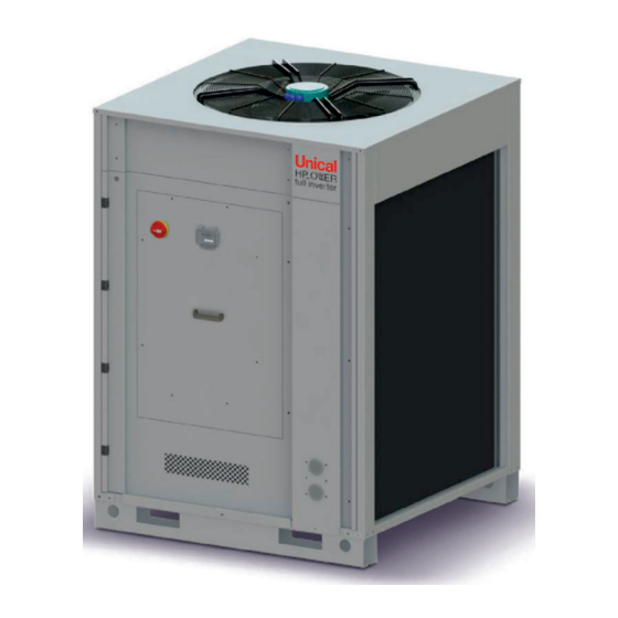
- Page 1 250 - 350 - 500 User’s and Installer’s Manual...
-
Page 2: Table Of Contents
Plant circuit filling ................................. 9 6.4.4 Plant drainage system ..............................10 REFRIGERANT DIAGRAMS .............................10 6.5.1 Refrigerant diagram of the model HP_OWER 250N – 350N ..................10 6.5.2 Refrigerant diagram of the model HP_OWER 500N ....................11 ELECTRICAL CONNECTIONS ............................11 6.6.1 Power supply terminal block ............................12 6.6.2... -
Page 3: Aim And Contents Of This Manual
CIRCULATOR’S CURVES ..............................26 15.1 MODELS HP_OWER 250N – 350N ........................... 26 15.2 MODEL HP_OWER 500N ..............................26 15.4 CIRCULATOR CHARACTERISTICS ..........................27 HEAD LOSS CURVES OF THE HYDRONIC CIRCUIT....................27 CHARACTERISTIC CURVE OF THE CONTROL VALVE FOR UNIT IN PARALLEL .......... 28 ACCESSORIES TO REDUCE THE NOISE LEVEL ...................... - Page 4 • The location of the plant, the hydraulic and electrical circuits must be established by the planting designer and must take into account both technical requirements as well as any applicable local laws and authorized specifications. • The execution of all works must be performed by skilled and qualified personnel, competent in the existing rules in different countries.
-
Page 5: General Safety Guidelines
GENERAL SAFETY GUIDELINES Before beginning to operate on HP_OWER units every user has to be perfectly knowledgeable about the functions of the equipment and its controls and has to have read and understood the information listed in this manual. It’s strictly forbidden to remove and/or tamper with any safety device. Children or unassisted disabled persons are not allowed to use the appliance. -
Page 6: Refrigerant Safety Data Sheet
REFRIGERANT SAFETY DATA SHEET Name: R410A (50% Difluoromethane (R32); 50% Pentafluoroethane (R125). RISKS INDICATIONS Major risks: Asphyxia Specific risks: The rapid evaporation may cause freezing. FIRST AID General informations: Never give anything by mouth to an unconscious person. Inhalation: Move to fresh air. Oxygen or artificial respiration if necessary. -
Page 7: Available Versions, Sizes And Accessories
HP_OWER AVAILABLE VERSIONS, SIZES AND ACCESSORIES Model Description Standard configuration code HP_OWER 250 Size 25 kW 00269135 HP_OWER 350 Size 35 kW 00268661 HP_OWER 500 Size 50 kW 00269137 Name of factory-fitted accessories: CODE Descrizione NAME 00264032/33 High efficiency integrated circulator 00264035 Antifreeze kit 00264034... -
Page 8: Lifting And Handling
An absolute care has to be taken to ensure adequate air volume to the condenser. The re-circulation of discharge air has to be avoided; failure to observe this point will result in poor performance or activation of safety controls. For these reasons it is necessary to observe the following clearances: MOD. HP_OWER 250N 1500 1000 HP_OWER 350N... -
Page 9: Hydraulic Circuit
WARNING: Make sure that, when designing the pipe length and diameter do not exceed the maximum head loss on the plant side, please see the technical data given in the table of Paragraph 0 (available head pressure). WARNING: In the models of HP_OWER series, the expansion vessel is not integrated on the plant side. The actual capacity of plant circuit should be checked by the installer in order to provide an expansion tank with adequate WARNING: Connect the pipes to the attacks by using always key against key system. -
Page 10: Plant Drainage System
(in order to make easy the operation, it is recommended to install externally two draining valves, on the water inlet and on the water outlet, between the unit and the manual gate valves). REFRIGERANT DIAGRAMS 6.5.1 Refrigerant diagram of the model HP_OWER 250N – 350N INVERTER COMPRESSOR COMPRESSOR INLET TEMPERATURE COMPRESSOR OUTLET TEMPERATURE... -
Page 11: Refrigerant Diagram Of The Model Hp_Ower 500N
6.5.2 Refrigerant diagram of the model HP_OWER 500N INVERTER COMPRESSOR COMPRESSOR INLET TEMPERATURE COMPRESSOR OUTLET TEMPERATURE HIGH PRESSURE TRANSDUCER HIGH PRESSURE FLOW SWITCH LOW PRESSURE TRANSDUCER LIQUID SEPARATOR CYCLE REVERSING VALVE LIQUID RECEIVER ELECTRONIC EXPANSION VALVE FILTER AXIAL FAN OUTDOOR AIR TEMPERATURE SENSOR CIRCULATOR ON BOARD UNIT WATER INLET TEMPERATURE WATER OUTLET TEMPERATURE... -
Page 12: Power Supply Terminal Block
• Wait for 90 seconds before getting access to the electrical panel. • Be sure that the grounding connection is good before carrying out any repairs. • Be sure that you are well insulated from the ground, with dry hands and feet, or by using insulating platforms and gloves. -
Page 13: Pm Module Phase Protection
(2) The management of the relaunching circulator requires the optional “GI” module code 00264034 6.6.3 PM Module phase protection The PM module detects the correct sequence of the 3-phases (L1, L2, and L3) power supply. The 3-phases power supply must be connected respecting the correct sequence of the phases so as to ensure the right direction of rotation at the compressor start-up and during operation. -
Page 14: Start Up
START UP Before start-up: • Check out the availability of the supplied wiring diagrams and manuals of the installed appliance. • Check out the availability of the electrical and hydraulic diagrams of the plant in which the unit is installed. Check that the shut-off valves of the hydraulic circuits are open. -
Page 15: Maintenance And Periodical Controls
10 MAINTENANCE AND PERIODICAL CONTROLS If the temperature drops below 0°C there is serious danger of frost: add a mixture of water and glycol in the plant, otherwise drain the hydraulic circuits of the plant and of the heat pump. WARNING: if the ambient temperature becomes lower than -15°C , in case the unit is turned off and powered down also for short periods, it’s compulsory to drain the plant and the hydraulic circuit of the unit by the mixture of water and glycol. -
Page 16: Environmental Protection
It is a good rule to carry out periodic checks in order to verify the proper operation of the unit. OPERATION 1 month 4 month 6 month Charging the water circuit. Presence of bubbles in the water circuit. Check if the safety and control devices work correctly Check if there is oil leakage from compressor. -
Page 17: Technical Data
12 TECHNICAL DATA 12.1 STANDARD VERSION HP_OWER 250N + 350N + 500N + TECHNICAL CHARACTERISTICS Unit 250N 350N 500N Integrated Integrated Integrated circulator circulator circulator Power supply 400V/3P+N+T/50Hz 400V/3P+N+T/50Hz 400V/3P+N+T/50Hz Electric data Maximum power input 14,83 15,14 19,16 19,47 28,62 29,09 Maximum current input 21,4... -
Page 18: Product Fiche And Technical Parameters According To Regulation (Eu) No 811/2013
WARNING: The minimum temperature allowed for storing the unit is 5°C. 12.2 PRODUCT FICHE AND TECHNICAL PARAMETERS ACCORDING TO REGULATION (EU) No 811/2013 PRODUCT FICHE – HP_OWER for low-temperature application (Tout: 35°C) Supplier’s name UNICAL A.G. spa Model HP_OWER 250 HP_OWER 350... -
Page 19: Technical Parameters For Heat Pump Low Temperature (Tout: 35° C)
Technical parameters for heat pump low temperature (Tout: 35° C) Model HP_OWER 250 Air-to-water heat pump: Water-to-water heat pump: Brine-to-water heat pump: Low-temperature heat pump: Equipped with a supplementary heater: Heat pump combination heater: Parameters are declared for low-temperature application. Parameters are declared for average climate condition. -
Page 20: Technical Parameters For Heat Pump Low Temperature (Tout: 35° C)
Technical parameters for heat pump low temperature (Tout: 35° C) Model HP_OWER 350 Air-to-water heat pump: Water-to-water heat pump: Brine-to-water heat pump: Low-temperature heat pump: Equipped with a supplementary heater: Heat pump combination heater: Parameters are declared for low-temperature application. Parameters are declared for average climate condition. -
Page 21: Technical Parameters For Heat Pump Low Temperature (Tout: 35° C)
Technical parameters for heat pump low temperature (Tout: 35° C) Model HP_OWER 500 Air-to-water heat pump: Water-to-water heat pump: Brine-to-water heat pump: Low-temperature heat pump: Equipped with a supplementary heater: Heat pump combination heater: Parameters are declared for low-temperature application. Parameters are declared for average climate condition. -
Page 22: Technical Parameters For Heat Pump Space Heaters Medium Temperature (Tout: 55°C)
Technical parameters for heat pump space heaters medium temperature (Tout: 55°C) Model HP_OWER 250 Air-to-water heat pump: Water-to-water heat pump: Brine-to-water heat pump: Low-temperature heat pump: Equipped with a supplementary heater: Heat pump combination heater: Parameters shall be declared for medium-temperature application. Parameters shall be declared for average climate condition. -
Page 23: Technical Parameters For Heat Pump Space Heaters Medium Temperature (Tout: 55°C)
Technical parameters for heat pump space heaters medium temperature (Tout: 55°C) Model HP_OWER 350 Air-to-water heat pump: Water-to-water heat pump: Brine-to-water heat pump: Low-temperature heat pump: Equipped with a supplementary heater: Heat pump combination heater: Parameters shall be declared for medium-temperature application. Parameters shall be declared for average climate condition. -
Page 24: Technical Parameters For Heat Pump Space Heaters Medium Temperature (Tout: 55°C)
Technical parameters for heat pump space heaters medium temperature (Tout: 55°C) Model HP_OWER 500 Air-to-water heat pump: Water-to-water heat pump: Brine-to-water heat pump: Low-temperature heat pump: Equipped with a supplementary heater: Heat pump combination heater: Parameters shall be declared for medium-temperature application. Parameters shall be declared for average climate condition. -
Page 25: A-Weighted Sound Power
12.3 A-WEIGHTED SOUND POWER Toltal L dB(A) Octave bands L dB(A) Size Fitting out LW(A) 63 Hz 125 Hz 250 Hz 500 Hz 1.000 Hz 2.000 Hz 4.000 Hz 8.000 Hz Standard 70,1 46,8 56,5 60,9 64,0 64,5 62,8 56,9 58,1 250N 68,3... -
Page 26: Circulator's Curves
15 CIRCULATOR’S CURVES 15.1 MODELS HP_OWER 250N – 350N Configuration with integrated circulator, control via PWM1 signal Configuration with auto-adaptive circulator (with the possibility of choice between constant ∆P and variable ∆P) 15.2 MODEL HP_OWER 500N Configuration with integrated circulator, control via 0-10 volt... -
Page 27: Circulator Characteristics
We obtain the pressure head of the circulating pump from the addition of the head losses of the hydronic circuit and the available head pressure. For example: for the model HP_OWER 250N with nominal water flow 1,01 L/s we obtain: 30 kPa (head loss) + 88 kPa (available head pressure)=118 kPa (circulator head pressure). -
Page 28: Characteristic Curve Of The Control Valve For Unit In Parallel
ON/OFF motorized valve should be added to those reported in the curves of Paragraph 17. For example: for the model HP_OWER 250N with nominal water flow 1,01L/s, we obtaine 1,4kPa (valve head loss) + 30kPa (hydronic circuit head loss)=34,9 kPa (total internal head loss). -
Page 29: Operating Limits
19 OPERATING LIMITS 19.1 EVAPORATOR WATER FLOW RATE The nominal water flow rate is referred to a ∆T equal to 5°C, between the evaporator’s inlet and outlet temperatures. The allowed maximum flow rate is corresponding to ∆T=3°C. Higher values may produce too high pressure drops. The allowed minimum water flow rate is corresponding to ∆T=8°C. -
Page 30: Correction Factors For Use Of Glycol
WATER CHILLER/HEAT PUMP MODES Heat pump mode Chiller mode Ambient temperature [°C] DOMESTIC HOT WATER MODE Domestic hot water mode Ambient temperature [°C] 20 CORRECTION FACTORS FOR USE OF GLYCOL Glycol rate Freezing point (°C) IPCF WFCF PDCF -3,2 0,985 1,02 1,08 -7,8... -
Page 31: Dimensions
Max Packing height with Height H Max Packing height Model AXITOP (Versions AXITOP (Versions SSL) [mm] (*) [mm] SSL) [mm] [mm] HP_OWER 250N – 350N 1673 1906 1785 2030 HP_OWER 500N 1745 1910 1890 2055 (*) Some units could be shipped with another type of packaging, only in case of no accessory AXITOP. The maximum height should... -
Page 32: Electric Panel
ELECTRIC PANEL N.B. The number of indicated components can vary depending on the model. The representation of the units is indicative and useful to present the main components and can therefore vary from the purchased one. The front panel is closed Disconnecting switch with door lock for electric box... - Page 33 The accessibility to the electrical box is from the front enclosure panel (with closed unit) The electric box is opened User display EMI filters Contactors Fuses-support Disconnecting switch with door lock Inductance onduits Cables’ c Driver board (one for each inverter compressor On-board terminal block and user’s terminal block...
- Page 36 - export@unical-ag.com - www.unical.eu Unical will not be held responsible for possible inaccuracies if due to transcription or printing errors. It also reserves the right to modify its products as deemed necessary or useful, without jeopardising their essential features.
Need help?
Do you have a question about the HP_OWER 250N and is the answer not in the manual?
Questions and answers