
Subscribe to Our Youtube Channel
Related Manuals for Powerline P1.1x


Summary of Contents for Powerline P1.1x
-
Page 6: Required Tools
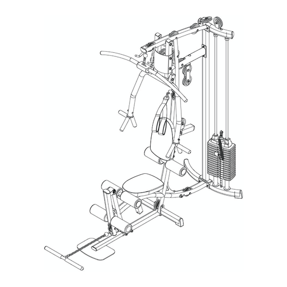
Preparations CAUTION: To set up this unit, you will need assistance. Do not attempt assembly by yourself. You must review and follow the instructions in this Owner’s Manual. If you do not assemble and use the P1 gym according to these guidelines, you could void the warranty. CAUTION: Obtain assistance! Do not attempt Required Tools to assemble the P1 by yourself. - Page 10 S T E P Be careful to assemble all components in the sequence they are presented. NOTE: At this point you must make sure that the gym is level, stable and in the right location. Place two Weight Stack Risers (F)* and two Rubber Donuts (29) onto Rear Leg (B) as shown. Slide two Guide Rods (G) through the Rubber Donuts (29), through the two Weight Stack Risers (F), and into the Rear Leg (B).
- Page 12 S T E P Be careful to assemble all components in the sequence they are presented. Insert Plastic Bushing (93) into the Lower Main Frame (A) as shown. Insert Front Foot Plate (J) into the Plastic Bushing (93) in the Lower Main Frame (A) as shown and attach using: Two 52 (10mm x 95mm hex head bolt) - No.
- Page 18 S T E P Be careful to assemble all components in the sequence they are presented. Slide Foam Roller Bar* (39) into the opening in Lower Main Frame (A) as shown. Slide two Plastic Washer (25) and two Foam Rollers (22) onto Foam Roller Bar* (39) as shown. Hold Foam Rollers (22) in place with two Plastic Roller End Cap (24) as shown.
- Page 20 S T E P Be careful to assemble all components in the sequence they are presented. High Pulley Cable (90) Ball Stop End Metal Ball End Note: All Pulleys in this step are 4 1/4” diameter, except where noted in step 7B and 7C. Leave all pulley bolts hand tight until step 10 is completed.
- Page 22 S T E P Be careful to assemble all components in the sequence they are presented. High Pulley Cable (90) Ball Stop End Metal Ball End Note: All Pulleys in this step are 4 1/4” diameter, except where noted in step 8c. Leave all pulley bolts hand tight until step 10 is completed.
- Page 24 S T E P Be careful to assemble all components in the sequence they are presented. Low Pulley Cable (91) Small Ball End Ball Stop End Note: All Pulleys in this step are 4 1/4” diameter, except where noted in step 9B. Leave all pulley bolts hand tight until step 10 is completed.
- Page 26 S T E P Be careful to assemble all components in the sequence they are presented. Low Pulley Cable (91) Small Ball End Ball Stop End Short Cable (92) Stamped Eye End Stamped Eye End Note: All Pulleys in this step are 4 1/4” diameter, except where noted in step 9C. Leave all pulley bolts hand tight until step 10 is completed.
- Page 63 SPACER...
Need help?
Do you have a question about the P1.1x and is the answer not in the manual?
Questions and answers